EP0680884B1 - Seamless can with necked-in portion - Google Patents
Seamless can with necked-in portion Download PDFInfo
- Publication number
- EP0680884B1 EP0680884B1 EP19950106458 EP95106458A EP0680884B1 EP 0680884 B1 EP0680884 B1 EP 0680884B1 EP 19950106458 EP19950106458 EP 19950106458 EP 95106458 A EP95106458 A EP 95106458A EP 0680884 B1 EP0680884 B1 EP 0680884B1
- Authority
- EP
- European Patent Office
- Prior art keywords
- necked
- seamless
- steel sheet
- thickness
- ironing
- Prior art date
- Legal status (The legal status is an assumption and is not a legal conclusion. Google has not performed a legal analysis and makes no representation as to the accuracy of the status listed.)
- Revoked
Links
- 229910000831 Steel Inorganic materials 0.000 claims description 45
- 239000010959 steel Substances 0.000 claims description 45
- 229920005989 resin Polymers 0.000 claims description 28
- 239000011347 resin Substances 0.000 claims description 28
- 229910052799 carbon Inorganic materials 0.000 claims description 24
- OKTJSMMVPCPJKN-UHFFFAOYSA-N Carbon Chemical compound [C] OKTJSMMVPCPJKN-UHFFFAOYSA-N 0.000 claims description 23
- 238000010409 ironing Methods 0.000 claims description 15
- IJGRMHOSHXDMSA-UHFFFAOYSA-N Atomic nitrogen Chemical compound N#N IJGRMHOSHXDMSA-UHFFFAOYSA-N 0.000 claims description 12
- 238000000137 annealing Methods 0.000 claims description 12
- 229910052782 aluminium Inorganic materials 0.000 claims description 7
- XAGFODPZIPBFFR-UHFFFAOYSA-N aluminium Chemical compound [Al] XAGFODPZIPBFFR-UHFFFAOYSA-N 0.000 claims description 7
- 229910052757 nitrogen Inorganic materials 0.000 claims description 6
- 239000010410 layer Substances 0.000 description 13
- 230000015572 biosynthetic process Effects 0.000 description 11
- 230000007797 corrosion Effects 0.000 description 8
- 238000005260 corrosion Methods 0.000 description 8
- 239000000853 adhesive Substances 0.000 description 6
- 230000001070 adhesive effect Effects 0.000 description 6
- 239000003973 paint Substances 0.000 description 6
- 230000037303 wrinkles Effects 0.000 description 6
- 101100327917 Caenorhabditis elegans chup-1 gene Proteins 0.000 description 5
- 229910000655 Killed steel Inorganic materials 0.000 description 5
- 238000005336 cracking Methods 0.000 description 5
- 238000005097 cold rolling Methods 0.000 description 4
- 238000001816 cooling Methods 0.000 description 4
- 229920001577 copolymer Polymers 0.000 description 4
- 230000007423 decrease Effects 0.000 description 4
- -1 polyethylene terephthalate copolymer Polymers 0.000 description 4
- 239000004593 Epoxy Substances 0.000 description 3
- 230000006835 compression Effects 0.000 description 3
- 238000007906 compression Methods 0.000 description 3
- 230000003247 decreasing effect Effects 0.000 description 3
- 230000007547 defect Effects 0.000 description 3
- 238000011049 filling Methods 0.000 description 3
- XEEYBQQBJWHFJM-UHFFFAOYSA-N iron Substances [Fe] XEEYBQQBJWHFJM-UHFFFAOYSA-N 0.000 description 3
- 238000000034 method Methods 0.000 description 3
- 229920003023 plastic Polymers 0.000 description 3
- 239000004033 plastic Substances 0.000 description 3
- 239000000758 substrate Substances 0.000 description 3
- LLLVZDVNHNWSDS-UHFFFAOYSA-N 4-methylidene-3,5-dioxabicyclo[5.2.2]undeca-1(9),7,10-triene-2,6-dione Chemical compound C1(C2=CC=C(C(=O)OC(=C)O1)C=C2)=O LLLVZDVNHNWSDS-UHFFFAOYSA-N 0.000 description 2
- 229920002433 Vinyl chloride-vinyl acetate copolymer Polymers 0.000 description 2
- 238000013459 approach Methods 0.000 description 2
- 235000014171 carbonated beverage Nutrition 0.000 description 2
- 239000011248 coating agent Substances 0.000 description 2
- 238000000576 coating method Methods 0.000 description 2
- 239000010960 cold rolled steel Substances 0.000 description 2
- 238000010438 heat treatment Methods 0.000 description 2
- 238000004519 manufacturing process Methods 0.000 description 2
- 239000000463 material Substances 0.000 description 2
- 150000001247 metal acetylides Chemical group 0.000 description 2
- 238000013508 migration Methods 0.000 description 2
- 230000005012 migration Effects 0.000 description 2
- 125000004433 nitrogen atom Chemical group N* 0.000 description 2
- 239000012044 organic layer Substances 0.000 description 2
- 230000002093 peripheral effect Effects 0.000 description 2
- 238000002791 soaking Methods 0.000 description 2
- 238000009987 spinning Methods 0.000 description 2
- 238000007669 thermal treatment Methods 0.000 description 2
- 229920001187 thermosetting polymer Polymers 0.000 description 2
- 239000005029 tin-free steel Substances 0.000 description 2
- VYZAMTAEIAYCRO-UHFFFAOYSA-N Chromium Chemical compound [Cr] VYZAMTAEIAYCRO-UHFFFAOYSA-N 0.000 description 1
- 229920001634 Copolyester Polymers 0.000 description 1
- JOYRKODLDBILNP-UHFFFAOYSA-N Ethyl urethane Chemical compound CCOC(N)=O JOYRKODLDBILNP-UHFFFAOYSA-N 0.000 description 1
- JHWNWJKBPDFINM-UHFFFAOYSA-N Laurolactam Chemical compound O=C1CCCCCCCCCCCN1 JHWNWJKBPDFINM-UHFFFAOYSA-N 0.000 description 1
- 229920000571 Nylon 11 Polymers 0.000 description 1
- 229920000299 Nylon 12 Polymers 0.000 description 1
- 229920002292 Nylon 6 Polymers 0.000 description 1
- 229920002302 Nylon 6,6 Polymers 0.000 description 1
- 239000004952 Polyamide Substances 0.000 description 1
- 239000004698 Polyethylene Substances 0.000 description 1
- 229920001328 Polyvinylidene chloride Polymers 0.000 description 1
- ATJFFYVFTNAWJD-UHFFFAOYSA-N Tin Chemical compound [Sn] ATJFFYVFTNAWJD-UHFFFAOYSA-N 0.000 description 1
- 230000005856 abnormality Effects 0.000 description 1
- NIXOWILDQLNWCW-UHFFFAOYSA-N acrylic acid group Chemical group C(C=C)(=O)O NIXOWILDQLNWCW-UHFFFAOYSA-N 0.000 description 1
- 239000012790 adhesive layer Substances 0.000 description 1
- 230000032683 aging Effects 0.000 description 1
- PNEYBMLMFCGWSK-UHFFFAOYSA-N aluminium oxide Inorganic materials [O-2].[O-2].[O-2].[Al+3].[Al+3] PNEYBMLMFCGWSK-UHFFFAOYSA-N 0.000 description 1
- 235000013405 beer Nutrition 0.000 description 1
- 238000007664 blowing Methods 0.000 description 1
- 150000001721 carbon Chemical group 0.000 description 1
- HGAZMNJKRQFZKS-UHFFFAOYSA-N chloroethene;ethenyl acetate Chemical compound ClC=C.CC(=O)OC=C HGAZMNJKRQFZKS-UHFFFAOYSA-N 0.000 description 1
- ZCDOYSPFYFSLEW-UHFFFAOYSA-N chromate(2-) Chemical compound [O-][Cr]([O-])(=O)=O ZCDOYSPFYFSLEW-UHFFFAOYSA-N 0.000 description 1
- 229910052804 chromium Inorganic materials 0.000 description 1
- 239000011651 chromium Substances 0.000 description 1
- 235000013353 coffee beverage Nutrition 0.000 description 1
- 230000032798 delamination Effects 0.000 description 1
- 210000003298 dental enamel Anatomy 0.000 description 1
- 230000006866 deterioration Effects 0.000 description 1
- 238000007723 die pressing method Methods 0.000 description 1
- 235000013399 edible fruits Nutrition 0.000 description 1
- 238000005516 engineering process Methods 0.000 description 1
- 229920006332 epoxy adhesive Polymers 0.000 description 1
- 239000005038 ethylene vinyl acetate Substances 0.000 description 1
- 239000000835 fiber Substances 0.000 description 1
- 239000012535 impurity Substances 0.000 description 1
- 239000011261 inert gas Substances 0.000 description 1
- 229920000554 ionomer Polymers 0.000 description 1
- 229910052742 iron Inorganic materials 0.000 description 1
- 238000003475 lamination Methods 0.000 description 1
- 229910052751 metal Inorganic materials 0.000 description 1
- 239000002184 metal Substances 0.000 description 1
- 229920001200 poly(ethylene-vinyl acetate) Polymers 0.000 description 1
- 229920002647 polyamide Polymers 0.000 description 1
- 229920001707 polybutylene terephthalate Polymers 0.000 description 1
- 229920000728 polyester Polymers 0.000 description 1
- 229920006267 polyester film Polymers 0.000 description 1
- 229920000573 polyethylene Polymers 0.000 description 1
- 229920000139 polyethylene terephthalate Polymers 0.000 description 1
- 239000005020 polyethylene terephthalate Substances 0.000 description 1
- 239000004800 polyvinyl chloride Substances 0.000 description 1
- 229920000915 polyvinyl chloride Polymers 0.000 description 1
- 239000005033 polyvinylidene chloride Substances 0.000 description 1
- 238000003825 pressing Methods 0.000 description 1
- 230000002035 prolonged effect Effects 0.000 description 1
- 238000005096 rolling process Methods 0.000 description 1
- 238000007789 sealing Methods 0.000 description 1
- 229920003048 styrene butadiene rubber Polymers 0.000 description 1
- 239000000126 substance Substances 0.000 description 1
- 239000002344 surface layer Substances 0.000 description 1
- 230000003746 surface roughness Effects 0.000 description 1
- 229920003051 synthetic elastomer Polymers 0.000 description 1
- 239000005061 synthetic rubber Substances 0.000 description 1
- 238000012360 testing method Methods 0.000 description 1
- 229920001169 thermoplastic Polymers 0.000 description 1
- 229920005992 thermoplastic resin Polymers 0.000 description 1
- 239000004416 thermosoftening plastic Substances 0.000 description 1
- 238000012546 transfer Methods 0.000 description 1
- 125000000391 vinyl group Chemical group [H]C([*])=C([H])[H] 0.000 description 1
Images


Classifications
-
- B—PERFORMING OPERATIONS; TRANSPORTING
- B65—CONVEYING; PACKING; STORING; HANDLING THIN OR FILAMENTARY MATERIAL
- B65D—CONTAINERS FOR STORAGE OR TRANSPORT OF ARTICLES OR MATERIALS, e.g. BAGS, BARRELS, BOTTLES, BOXES, CANS, CARTONS, CRATES, DRUMS, JARS, TANKS, HOPPERS, FORWARDING CONTAINERS; ACCESSORIES, CLOSURES, OR FITTINGS THEREFOR; PACKAGING ELEMENTS; PACKAGES
- B65D1/00—Containers having bodies formed in one piece, e.g. by casting metallic material, by moulding plastics, by blowing vitreous material, by throwing ceramic material, by moulding pulped fibrous material, by deep-drawing operations performed on sheet material
- B65D1/12—Cans, casks, barrels, or drums
- B65D1/14—Cans, casks, barrels, or drums characterised by shape
- B65D1/16—Cans, casks, barrels, or drums characterised by shape of curved cross-section, e.g. cylindrical
- B65D1/165—Cylindrical cans
-
- C—CHEMISTRY; METALLURGY
- C21—METALLURGY OF IRON
- C21D—MODIFYING THE PHYSICAL STRUCTURE OF FERROUS METALS; GENERAL DEVICES FOR HEAT TREATMENT OF FERROUS OR NON-FERROUS METALS OR ALLOYS; MAKING METAL MALLEABLE, e.g. BY DECARBURISATION OR TEMPERING
- C21D9/00—Heat treatment, e.g. annealing, hardening, quenching or tempering, adapted for particular articles; Furnaces therefor
- C21D9/46—Heat treatment, e.g. annealing, hardening, quenching or tempering, adapted for particular articles; Furnaces therefor for sheet metals
- C21D9/48—Heat treatment, e.g. annealing, hardening, quenching or tempering, adapted for particular articles; Furnaces therefor for sheet metals deep-drawing sheets
-
- Y—GENERAL TAGGING OF NEW TECHNOLOGICAL DEVELOPMENTS; GENERAL TAGGING OF CROSS-SECTIONAL TECHNOLOGIES SPANNING OVER SEVERAL SECTIONS OF THE IPC; TECHNICAL SUBJECTS COVERED BY FORMER USPC CROSS-REFERENCE ART COLLECTIONS [XRACs] AND DIGESTS
- Y10—TECHNICAL SUBJECTS COVERED BY FORMER USPC
- Y10S—TECHNICAL SUBJECTS COVERED BY FORMER USPC CROSS-REFERENCE ART COLLECTIONS [XRACs] AND DIGESTS
- Y10S220/00—Receptacles
- Y10S220/22—Seamless
-
- Y—GENERAL TAGGING OF NEW TECHNOLOGICAL DEVELOPMENTS; GENERAL TAGGING OF CROSS-SECTIONAL TECHNOLOGIES SPANNING OVER SEVERAL SECTIONS OF THE IPC; TECHNICAL SUBJECTS COVERED BY FORMER USPC CROSS-REFERENCE ART COLLECTIONS [XRACs] AND DIGESTS
- Y10—TECHNICAL SUBJECTS COVERED BY FORMER USPC
- Y10S—TECHNICAL SUBJECTS COVERED BY FORMER USPC CROSS-REFERENCE ART COLLECTIONS [XRACs] AND DIGESTS
- Y10S220/00—Receptacles
- Y10S220/906—Beverage can, i.e. beer, soda
-
- Y—GENERAL TAGGING OF NEW TECHNOLOGICAL DEVELOPMENTS; GENERAL TAGGING OF CROSS-SECTIONAL TECHNOLOGIES SPANNING OVER SEVERAL SECTIONS OF THE IPC; TECHNICAL SUBJECTS COVERED BY FORMER USPC CROSS-REFERENCE ART COLLECTIONS [XRACs] AND DIGESTS
- Y10—TECHNICAL SUBJECTS COVERED BY FORMER USPC
- Y10T—TECHNICAL SUBJECTS COVERED BY FORMER US CLASSIFICATION
- Y10T428/00—Stock material or miscellaneous articles
- Y10T428/13—Hollow or container type article [e.g., tube, vase, etc.]
- Y10T428/1352—Polymer or resin containing [i.e., natural or synthetic]
- Y10T428/1355—Elemental metal containing [e.g., substrate, foil, film, coating, etc.]
- Y10T428/1359—Three or more layers [continuous layer]
-
- Y—GENERAL TAGGING OF NEW TECHNOLOGICAL DEVELOPMENTS; GENERAL TAGGING OF CROSS-SECTIONAL TECHNOLOGIES SPANNING OVER SEVERAL SECTIONS OF THE IPC; TECHNICAL SUBJECTS COVERED BY FORMER USPC CROSS-REFERENCE ART COLLECTIONS [XRACs] AND DIGESTS
- Y10—TECHNICAL SUBJECTS COVERED BY FORMER USPC
- Y10T—TECHNICAL SUBJECTS COVERED BY FORMER US CLASSIFICATION
- Y10T428/00—Stock material or miscellaneous articles
- Y10T428/26—Web or sheet containing structurally defined element or component, the element or component having a specified physical dimension
- Y10T428/263—Coating layer not in excess of 5 mils thick or equivalent
- Y10T428/264—Up to 3 mils
-
- Y—GENERAL TAGGING OF NEW TECHNOLOGICAL DEVELOPMENTS; GENERAL TAGGING OF CROSS-SECTIONAL TECHNOLOGIES SPANNING OVER SEVERAL SECTIONS OF THE IPC; TECHNICAL SUBJECTS COVERED BY FORMER USPC CROSS-REFERENCE ART COLLECTIONS [XRACs] AND DIGESTS
- Y10—TECHNICAL SUBJECTS COVERED BY FORMER USPC
- Y10T—TECHNICAL SUBJECTS COVERED BY FORMER US CLASSIFICATION
- Y10T428/00—Stock material or miscellaneous articles
- Y10T428/31504—Composite [nonstructural laminate]
- Y10T428/31678—Of metal
- Y10T428/31681—Next to polyester, polyamide or polyimide [e.g., alkyd, glue, or nylon, etc.]
Definitions
- This invention relates to a seamless can with a necked-in portion for filling carbonated drinks, beer, coffee drinks, fruit drinks, etc.
- the diameter-reducing ratio is more than 10 %, particularly more than 15 %.
- Rough surface is unfavorable since it spoils adhesion between the cold-reduced steel sheet base and the organic coating, leading to deterioration of corrosion resistance.
- An object of the present invention is to provide an organic resin-coated seamless can with a necked-in portion, which scarecely suffers formation of rough surface and pinholes in the necked-in portion even when the diameter-reducing ratio of the necked-in portion is large.
- the seamless can of the present invention having a necked-in portion according to claim 1 is produced by subjecting a resin-coated steel sheet to drawing-re-drawing for reducing thickness or to drawing-re-drawing-ironing for reducing thickness and which has a ratio of diameter of necked-in portion to diameter of body of 0.9 or less than that, said steel sheet being coated by 5- to 30- ⁇ m thick organic resin layer on both surfaces of aluminum-killed, surface-treated steel sheet of 0.01 to 0.13 % by weight in total carbon amount and not more than 6.5 ⁇ m in average grain diameter having been subjected to over-aging after continuous annealing to adjust to not more than 10 ppm in solid-dissolved carbon amount.
- Fig. 1 is a partially cut front view of the first embodiment of a seamless can of the present invention having a necked-in portion.
- Fig. 2 is an enlarged view of portion A of the seamless can shown in Fig. 1.
- Fig. 3 1 is a vertical sectional view of shallowly drawn cup, 2 a re-drawn cup formed from the shallowly drawn cup, and 3 a seamless can formed from the re-drawn cup and before formation of the necked-in portion of the seamless can shown in Fig. 1.
- Fig. 4 is a vertical sectional view showing the step of forming the seamless can shown in Fig. 3 3 from the re-drawn cup shown in Fig. 3 2.
- Fig. 5 is a vertical sectional view showing the step of forming the necked-in portion and the flange from the seamless can shown in Fig. 3 3.
- Fig. 6 is a vertical sectional view showing the seamless can with a necked-in portion obtained in the second embodiment of the present invention.
- Fig. 7 is a vertical sectional view showing a second example of the step of forming the seamless can shown in Fig. 3 3 from the re-drawn cup shown in Fig. 3 2.
- numeral 10 designates a seamless can with a necked-in portion, 11 a body, 13 a necked-in portion, 15 a surface-treated steel sheet, 16 an organic resin layer on the inside surface, 17 an organic resin layer on the outside surface, 30 a seamless can with a necked-in portion, and 33 a necked-in portion.
- the over-aging is preferably conducted at 350 - 500°C.
- the amount of soluble Al is preferably 0.01 - 0.1 % by weight, and the amount of total nitrogen is preferably 0.006 % by weight or less than that.
- drawing includes ordinary re-drawing except for the re-drawing for reducing thickness.
- the re-drawing for reducing thickness is conducted by using a re-drawing die having a curvature radius Rd of the working corner 1 - 2.9 times as much as the thickness t 1 of the resin-coated steel sheet (substantially the same as t 1 shown in Fig. 2).
- re-drawing is specifically described below by reference to Fig. 4.
- a blank of resin-coated steel sheet having a thickness of t 1 is subjected to drawing and ordinary re-drawing to form a redrawn cup 1 (see Fig. 3 2).
- the bottom 1b of the redrawn cup is pressed into cavity 2c of a re-drawing die 2 by the top end of a punch 4 while pressing the side wall 1a (having a thickness of t 2 about the same as t 1 ) of the re-drawn cup 1 by the plane surface 2a of the re-drawing die 2 and the lower surface 3a of a blank holding member 3 to thereby conduct bending-unbending at a working corner 2b having a small curvature radius under a comparatively large back tension S 1 and a front tension S 2 .
- thickness of the side wall 1a is thinned to t 3 .
- the thickness-reducing ratio ⁇ (t 1 - t 3 ) x 100/t 1 % ⁇ is usually 15 to 40 %.
- Strain by the re-drawing for reducing thickness is much greater than that by the ordinary re-drawing due to compression in peripheral direction, tensile in vertical direction and compression in thickness direction.
- thickness of the steel sheet is reduced by the bending-stretching deformation at the working corner 2b with a small curvature radius Rd.
- the inventors have found that, when conventional cold-rolled steel sheet is used, there results seriously rough surface 6, i.e., serious surface roughness and surface waviness due to the local extension. It has also been found that this tends to be more serious as the number of times of re-drawing for reducing thickness increases and as the curvature radius Rd decreases.
- the aluminum-killed steel sheet of claim 1 which has an average grain size of up to 6.5 ⁇ m and a solid-dissolved carbon amount reduced to 10 ppm or less than that by overaging after continuous annealing, has a large total area of grain boundary and much carbide precipitated on the grain boundary or within grains.
- the grain boundary and the carbides function as the starting point of slip plane upon plastic deformation, and a number of slip planes rapidly appear in different directions in the steel portion on the working corner 2b and readily migrate without being intervened by lattice strain, which serves to smoothly complete the plastic deformation.
- the total carbon amount of the steel sheet is limited to 0.01 - 0.13 % by weight. If the amount is less than 0.01 % by weight, grains will grow too much upon continuous annealing, thus average grain size not being able to be decreased to 6.5 um or less. On the other hand, if more than 0.13 % by weight, the steel sheet will become so hard that longitudinal wrinkles appear around the opening and that cracking is liable to take place upon re-drawing.
- the amount of dissolved carbon is limited to 10 ppm or less than that. If more than 10 ppm, lattice strain will become so serious that the above-described migration of slip planes becomes difficult to take place, and number of precipitated carbides functioning as starting point of slip plane upon plastic deformation will become small. Steel sheets having been subjected to a batch annealing has the amount of dissolved carbon of 10 ppm or less, but are difficult to stably have the average grain size of up to 6.5 ⁇ m.
- the thickness of the organic resin coated on the steel sheet is limited to 5 - 30 ⁇ m. If thinner than 5 ⁇ m, there results deteriorated corrosion resistance even surface defects such as rough surface can be prevented to some extent. On the other hand, if thicker than 30 ⁇ m, wrinkles will not be able to be prevented upon drawing or re-drawing for reducing thickness, resulting in high tendency of formation of longitudinal wrinkles.
- the overaging temperature is lower than 350°C, the overaging step requires a prolonged time, thus such temperature not being preferred in view of production efficiency.
- the equilibrium amount of dissolved carbon atom in the steel will become so high that it becomes impossible to decrease the amount of solid-dissolved carbon to 10 ppm or less than that by the overaging, thus such temperature not being preferred.
- the amount of soluble aluminum is less than 0.01 % by weight, it will become difficult to fix nitrogen atoms and, as a result, dissolved nitrogen atoms in the steel increase in number, which prevents migration of slip planes. Thus, such amount is not preferred.
- more than 0.1 % by weight alumina type inclusions will liable to be formed, leading to formation of cracking or like defect upon drawing, re-drawing for reducing thickness, or necked-in working. Thus, such amount is not preferred.
- the steel will becomes so hard that longitudinal wrinkles are formed around the opening or cracking is liable to take place upon re-drawing.
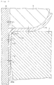
- Fig.1 shows seamless can 10 with necked-in portion which is an embodiment of the present invention.
- Seamless can 10 has a body 11, a bottom 12, a necked-in portion 13 and flange 14.
- the body is generally in a cylindrical form.
- Bottom 12 comprises an inwardly concave chime 12a , a circular projection 12b and a central panel 12c inwardly concave in a dome shape, and has an excellent resistance against pressure from inside. Therefore, the seamless can 10 is suited as a pressure can for filling carbonated drinks.
- a necked-in portion 13 comprises a shoulder 13a of a frustum shape and a neck 13b of a short cylindrical shape, which is of a type called a smooth necked-in portion. Thickness of the necked-in portion 13, flange 14 and an upper part 11a of the body is somewhat thicker than that of main body 11b which is a lower part of the body 11.
- the ratio of the minimum outer diameter of the necked-in portion (referred to as "diameter of necked-in portion” in this specification), D 2 , to the outer diameter of the body 11 (referred to as "body diameter” in this specification), D 1 , i.e., D 2 /D 1 is up to 0.9, more preferably 0.7 - 0.85.
- Fig. 2 shows an enlarged view of portion A of the central panel 12c of the bottom of the seamless can 10, wherein 15 desinates a surface treated steel sheet, 16 designates an inside organic resin layer, and 17 designates an outer organic resin layer.
- Thickness of the central panel 12c is substantially the same as a blank used as a material for forming the seamless can 10, or the surface treated steel sheet.
- Thickness of the surface treated steel sheet 15 is usually 0.1 - 0.4 mm, preferably 0.15 - 0.3 mm, and thickness of the organic resin layer 16 and 17 is 5 - 30 ⁇ m, preferably 10 - 25 ⁇ m.
- those surface treated steel sheet for use as cans which have an excellent adhesion to the organic resin layers 16 and 17, such as a tinned steel sheet comprising a steel substrate 15a having formed thereon surface layer 15b such as a tin layer or a chromium layer, a tin-free steel (electrolytic chromate treated steel sheet), a thin nickel-plated steel sheet, (electrically) zinc-plated steel sheet, etc., are preferably used.
- the steel sheet substrate 15a comprises an aluminum killed steel sheet of 0.01 to 0.13 % by weight in total carbon amount and not more than 6.5 ⁇ m in average grain diameter having been subjected to over-aging after continuous annealing to adjust to not more than 10 ppm in solid-dissolved carbon amount.
- the maximum grain diameter of the steel sheet substrate be preferably not more than about 15 ⁇ m, and the grains are preferably uniform in size.
- Continuously annealed steel sheets (composed of aluminum killed steel) usually have a solid-dissolved carbon amount of about 30 - about 40 ppm.
- the solid-dissolved carbon amount can be decreased to not more than 10 ppm by subjecting the annealed sheets to over-aging at 350 - 500°C, preferably 350 - 400°C for a period of T.
- the over-aging period T varies depending upon the over-aging temperature but, in general, about 5 minutes at 350°C or about 40 seconds at 450°C.
- the over-aging may be conducted batchwise by heating in a coil form in a separate step after the continuous annealing but, in view of attaining uniform over-aging, it is preferably cnducted in a cooling step of the continuous annealing.
- Secondary cold rolling ratio after the annealing and over-aging is preferably 0.5 to 40 %. If less than 0.5 %, stretcher strain will be liable to generate in the bottom or the like upon drawing and, if more than 40 %, the steel will become too hard and fibre texture seriously develops in the rolling direction, which leads to formation of longitudinal wrinkles or cause breaking upon drawing or re-drawing and ironing for reducing thickness.
- organic resin for forming organic resin layers 16 and 17 biaxially orientated polyester films are used, with polyethylene terephthalate copolymer films (e.g., ethylene terephthalate/isophthalate copolymer film of 88/12 in molar ratio) being particularly preferred.
- polyethylene terephthalate copolymer films e.g., ethylene terephthalate/isophthalate copolymer film of 88/12 in molar ratio
- Application of the film to the surface treated steel sheet 15 is usually conducted by thermocompression bonding optionally forming an adhesive layer therebetween.
- the outer resin layer 17 may be formed by coating as will be described hereinafter.
- the seamless can with a necked-in portion is manufactured, for example, in the following manner.
- An aluminum killed steel slab consisting of 0.01 - 0.13 % by weight of carbon, 0.01 - 0.1 % by weight of soluble aluminum, up to 0.006 % by weight of nitrogen, 0.1 - 1.0 % by weight of Mn, and the rest of Fe and unavoidable impurities is hot rolled and wound at a temperature at which grain size can be made small and a texture for reducing anisotropy can be optimized (about 600 - about 670°C).
- the resulting hot-rolled strip is acid-washed and subjected to a primary cold rolling to produce a cold-rolled strip.
- the cold-rolled strip is continuously annealed at a comparatively low soaking temperature (e.g., about 650 to about 700°C) for a short time to thereby reduce the size of grains and cooled in a cooling step to 350 to 500°C by, for example, blowing an inert gas, then subjected to the over-aging by maintaning at the aforementioned temperature for a predetermined period of time T, followed by cooling.
- a comparatively low soaking temperature e.g., about 650 to about 700°C
- over-aging it may be possible to supercool from the soaking temperature of the continuous annealing to a temperature lower than the over-aging temperature, re-heat to the over-aging temperature and, after keeping at the temperature for the predetermined over-aging time T, cool the strip or, alternatively, to supercool in the same manner and, after re-heating to the aforementioned temperature, conduct gradient over-aging by cooling to a predetermined temperature, for the purpose of effectively decreasing the amount of solid-dissolved carbon in a short time.
- batch annealing may be conducted separately at the above-described aging temperature after the ordinary continuous annealing.
- the resulting continuously annealed strip is subjected to a secondary cold rolling with a thickness reduction ratio of 0.5 to 40 % to obtain a secondary cold-rolled strip with a predetermined thickness.
- This secondary cold-rolled strip is electrically cleaned, then surface treated to produce a surface treated strip of, for example, tin-free steel.
- a 5 - 30- ⁇ m thick organic resin layer is applied to both sides of the surface treated strip by thermocompression bonding or the like to produce a resin-coated steel strip having a cross-sectional structure as shown in Fig. 2.
- the resin-coated steel strip is introduced into a drawing machine (not shown) to conduct blanking and drawing, thus a shallowly drawn cup 18 as shown in Fig. 3 1 being formed. Subsequently, the shallowly drawn cup 18 is re-drawn by a transfer press to form a re-drawn cup 1 (Fig. 3 2).
- the cup 1 is then re-drawn for reducing thickness by cooperation of a re-drawing die 2 for reducing thickness, a blank holding member 3 and a punch 4 shown in Fig. 4 to form a seamless can 20 having a body diameter of D 1 and a flange 20c. Then, the bottom of the seamless can 20 is worked to form a chime 12a, a circular projection 12b and a central panel 12c.
- the pre-necked-in portion 13' and the pre-flange 14' are worked by a working tool (not shown) to form a shoulder 13a having an arc-shaped cross-section and a flange 14 substantially parallel to the bottom plane 12d.
- tin-free steels composed of aluminum killed steel (Al content:0.04-0.07 % by weight; total nitrogen amount:0.002 - 0.005 % by weight; amount of solid-dissolved nitrogen: up to 1 ppm) having varying amounts of carbon, varying amounts of solid-dissolved carbon and varying average grain diameter and having a thickness of 0.175 mm and a secondary cold-rolling ratio of 30 % were prepared.
- a 20- ⁇ m thick ethylene terephthalate/isophthalate copolymer (molar ratio: 88/12) film was provided by thermocompression bonding on each side of the steel strips.
- Circular blanks of 166 mm in diameter were blanked from the resin-coated strips, and seamless cans 20 having a height, H, of 125 mm, a body diameter, D 1 , of 66 mm (corresponding to nominal can diameter of #211) and an average thickness of the side wall 20a (including the organic resin layers) of 0.14 mm were produced by the drawing-re-drawing for reducing thickness. Additionally, curvature radius Rd of the working corner 2 of the re-drawing die 2 was 0.3 mm.
- seamless cans 20 of the same size as described above shown in Table 1 were produced under the same working condition as described above using tin-free steels and resin-coated steel strips prepared under the same conditions as described above except for not conducting the over-aging.
- the amount of solid-dissolved carbon was measured in the following manner.
- Solid-dissolved carbon is precipitated on carbide by a thermal treatment of 250°C x 50 hours. Electric resistance is measured before and after the thermal treatment to obtain a decrease in electric resistance corresponding to the precipiration of solid-dissolved carbon on carbide. The decrease is converted into the amount of solid-dissolved carbon by using a contribution ratio of solid-dissolved carbon per unit concentration to specific resistance, 29.5 ⁇ cm/% by weight. (For example, see H>Abe et al; Trans. Iron steel Inst. Jpn., 21 (1981), p.100). Samples were cut out from the body of can.
- breaking generation ratio of the necked-in portion enamel rater value of cans (ERV; measured according to the method described in "Hoso Gijutu Binran (Wrapping Technology Handbook)", published by Nikkan Kogyo Shinbunsha on July, 20, 1983, p.1845), and corrosion resistance evaluated by filling them with cola and sealing them and leaving at 37°C for 6 months were measured. Results thus obtained are also shown in Table 1.
- the necked-in portion may be multi-stepped by die forming (three-stepped embodiment being shown as necked-in portion 33 in Fig. 6). In this case, too, D 2 /D 1 is not more than 0.9.
- the cup to be subjected to re-drawing for reducing thickness may be a shallowly drawn cup 18 (Fig. 3, 1).
- a seamless can 20 having a side wall 20a of t 4 in thickness may be formed by subjecting the side wall 1a of the re-drawn cup 1 to the re-drawing-ironing for reducing thickness using a die 7 for the re-drawing-ironing having a working corner 7b, approach surface 7c of an inverse frustum shape extending forward and slantward at an angle of ⁇ to the axis of die cavity, and an ironing part 7d of a short cylindrical shape in contact with the lower end of the approach surface 7c.
- This embodiment provides the advantage that the side wall 20a of the formed seamless can 20 can be more thinned and that thickness can be easily controlled.
- said re-drawn side wall 20a is ironed with an ironing ratio [(t 3 -t 4 )x100/t 3 ] of at least 5 %, preferably 10 - 40 %.
- the ironing enables one to more reduce and control the thickness of the side wall 20a of the seamless can 20 and, since the organic layers are smoothed, there is obtained an improved printability, and formation of rough surface is effectively prevented.
- thermoplastic resin films such as olefinic resins such as polyethylene, polypropylene, ethylene-propylene copolymer, ethylene-vinyl acetate copolymer, ethylene-acrylic ester copolymer and ionomer; films of polyesters such as polybutylene terephthalate; films of polyamides such as nylon 6, nylon 6,6, nylon 11 and nylon 12; a polyvinyl chloride film; a polyvinylidene chloride film; etc. These films may or may not be biaxially orientated.
- olefinic resins such as polyethylene, polypropylene, ethylene-propylene copolymer, ethylene-vinyl acetate copolymer, ethylene-acrylic ester copolymer and ionomer
- films of polyesters such as polybutylene terephthalate
- films of polyamides such as nylon 6, nylon 6,6, nylon 11 and nylon 12
- a polyvinyl chloride film a polyvinylidene
- an urethane adhesive an epoxy adhesive, an acid-modified olefinic resin adhesive, a copolyamide adhesive, a copolyester adhesive, etc. may preferably be used in a thickness of 0.1 to 5.0 ⁇ m.
- thermosetting paint may be applied to the surface treated steel sheet or to the film in a thickness of 0.05 - 2 ⁇ m as the adhesive.
- thermoplastic or thermosetting paints such as modified epoxy paints (e.g., phenol-epoxy, amino-epoxy, etc.), vinyl chloride-vinyl acetate copolymer, saponified vinyl chloride-vinyl acetate copolymer, vinyl chloride-vinyl acetate, maleic anhydride copolymer, epoxy-modified, epoxyamino-modified or epoxyphenol-modified vinyl paints, acrylic paints, synthetic rubber paints (e.g., styrene-butadiene copolymer, etc.) may be used alone or in combination of two or more.
- modified epoxy paints e.g., phenol-epoxy, amino-epoxy, etc.
- vinyl chloride-vinyl acetate copolymer saponified vinyl chloride-vinyl acetate copolymer
- vinyl chloride-vinyl acetate vinyl chloride-vinyl acetate, maleic anhydride copolymer
- the seamless can with a necked-in portion in accordance with the present invention enable one to use a can top having a comparatively small diameter, thus production cost being reduced.
- the can shows an excellent corrosion resistance against its contents.
Description
- This invention relates to a seamless can with a necked-in portion for filling carbonated drinks, beer, coffee drinks, fruit drinks, etc.
- It has been proposed to produce a seamless can having a side wall thinned by bend-stretching, by re-drawing a once drawn metal cap made of organic substance-coated cold-reduced steel sheet using a die having a working corner with a small curvature radius, said cold-rolled steel sheet having an average grain diameter of 6.5 µm or less and a tensile strength of 65 kg/mm2 or more (Japanese Unexamined Patent Publication No. 4-22519). However, this type seamless cans have been found to have the defect that, when subjected to neck-in working in a post-working process, the resulting necked-in
portion 13 will be liable to suffer formation of seriously rough surface 6 (see Fig. 1) and, in an extreme case, even pinholes if the degree of neck-in working is large, i.e., the diameter-reducing ratio is more than 10 %, particularly more than 15 %. Rough surface is unfavorable since it spoils adhesion between the cold-reduced steel sheet base and the organic coating, leading to deterioration of corrosion resistance. - An object of the present invention is to provide an organic resin-coated seamless can with a necked-in portion, which scarecely suffers formation of rough surface and pinholes in the necked-in portion even when the diameter-reducing ratio of the necked-in portion is large.
- The seamless can of the present invention having a necked-in portion according to
claim 1 is produced by subjecting a resin-coated steel sheet to drawing-re-drawing for reducing thickness or to drawing-re-drawing-ironing for reducing thickness and which has a ratio of diameter of necked-in portion to diameter of body of 0.9 or less than that, said steel sheet being coated by 5- to 30-µm thick organic resin layer on both surfaces of aluminum-killed, surface-treated steel sheet of 0.01 to 0.13 % by weight in total carbon amount and not more than 6.5 µm in average grain diameter having been subjected to over-aging after continuous annealing to adjust to not more than 10 ppm in solid-dissolved carbon amount. - Other objects, features and advantages of the present invention will become apparent from the detailed description of the preferred embodiments of the invention to follow.
- Fig. 1 is a partially cut front view of the first embodiment of a seamless can of the present invention having a necked-in portion.
- Fig. 2 is an enlarged view of portion A of the seamless can shown in Fig. 1.
- Fig. 3 ① is a vertical sectional view of shallowly drawn cup, ② a re-drawn cup formed from the shallowly drawn cup, and ③ a seamless can formed from the re-drawn cup and before formation of the necked-in portion of the seamless can shown in Fig. 1.
- Fig. 4 is a vertical sectional view showing the step of forming the seamless can shown in Fig. 3 ③ from the re-drawn cup shown in Fig. 3 ②.
- Fig. 5 is a vertical sectional view showing the step of forming the necked-in portion and the flange from the seamless can shown in Fig. 3 ③.
- Fig. 6 is a vertical sectional view showing the seamless can with a necked-in portion obtained in the second embodiment of the present invention.
- Fig. 7 is a vertical sectional view showing a second example of the step of forming the seamless can shown in Fig. 3 ③ from the re-drawn cup shown in Fig. 3 ②.
- In these Figures,
numeral 10 designates a seamless can with a necked-in portion, 11 a body, 13 a necked-in portion, 15 a surface-treated steel sheet, 16 an organic resin layer on the inside surface, 17 an organic resin layer on the outside surface, 30 a seamless can with a necked-in portion, and 33 a necked-in portion. - The over-aging is preferably conducted at 350 - 500°C. The amount of soluble Al is preferably 0.01 - 0.1 % by weight, and the amount of total nitrogen is preferably 0.006 % by weight or less than that.
- Additionally, in this specification, the term "drawing" includes ordinary re-drawing except for the re-drawing for reducing thickness.
- As is described in Japanese Unexamined Patent Publication No. 1-258822, the re-drawing for reducing thickness is conducted by using a re-drawing die having a curvature radius Rd of the working corner 1 - 2.9 times as much as the thickness t1 of the resin-coated steel sheet (substantially the same as t1 shown in Fig. 2).
- The re-drawing is specifically described below by reference to Fig. 4. A blank of resin-coated steel sheet having a thickness of t1 is subjected to drawing and ordinary re-drawing to form a redrawn cup 1 (see Fig. 3 ②). The bottom 1b of the redrawn cup is pressed into cavity 2c of a
re-drawing die 2 by the top end of apunch 4 while pressing theside wall 1a (having a thickness of t2 about the same as t1) of there-drawn cup 1 by the plane surface 2a of there-drawing die 2 and the lower surface 3a of ablank holding member 3 to thereby conduct bending-unbending at a workingcorner 2b having a small curvature radius under a comparatively large back tension S1 and a front tension S2. Thus, thickness of theside wall 1a is thinned to t3. The thickness-reducing ratio {(t1 - t3) x 100/t1 %} is usually 15 to 40 %. - In ordinary re-drawing, reduction in thickness of steel sheet by the bending-unbending deformation at the working
corner 2b scarcely takes place because of a large curvature radius Rd and, at the upper portion of the body of re-drawn cans, there results a thickened steel sheet due to large compression in the peripheral direction. - Strain by the re-drawing for reducing thickness is much greater than that by the ordinary re-drawing due to compression in peripheral direction, tensile in vertical direction and compression in thickness direction. In addition, in the re-drawing for reducing thickness, thickness of the steel sheet is reduced by the bending-stretching deformation at the working
corner 2b with a small curvature radius Rd. Upon this thickness reduction, there arises local extension. The inventors have found that, when conventional cold-rolled steel sheet is used, there results seriouslyrough surface 6, i.e., serious surface roughness and surface waviness due to the local extension. It has also been found that this tends to be more serious as the number of times of re-drawing for reducing thickness increases and as the curvature radius Rd decreases. - In particular, in the latter stage of the re-drawing for reducing thickness, above all, in the stage of re-drawing the portion within about 20 mm from the opening end of seamless can, back tension S1 becomes considerably small and liable to vary, which is considered to make the
rough surface 6 more rough. Thisrough surface 6 becomes more serious by the bend-stretching upon neck-in flange working, which in some cases results in formation of pinholes, breaking of the material or cracking of flange. - The aluminum-killed steel sheet of
claim 1, which has an average grain size of up to 6.5 µm and a solid-dissolved carbon amount reduced to 10 ppm or less than that by overaging after continuous annealing, has a large total area of grain boundary and much carbide precipitated on the grain boundary or within grains. - The grain boundary and the carbides function as the starting point of slip plane upon plastic deformation, and a number of slip planes rapidly appear in different directions in the steel portion on the working
corner 2b and readily migrate without being intervened by lattice strain, which serves to smoothly complete the plastic deformation. - These may contribute to reduced
rough surface 6 in theside wall portion 1a and formation of comparatively smoothouter surface 1a1 andinner surface 1a2 of the side wall (see Fig. 4). This may serve to prevent the problems of formation of rough surface and pinholes in the necked-in portion and flange cracking upon necked-in flange working. - The total carbon amount of the steel sheet is limited to 0.01 - 0.13 % by weight. If the amount is less than 0.01 % by weight, grains will grow too much upon continuous annealing, thus average grain size not being able to be decreased to 6.5 um or less. On the other hand, if more than 0.13 % by weight, the steel sheet will become so hard that longitudinal wrinkles appear around the opening and that cracking is liable to take place upon re-drawing.
- The amount of dissolved carbon is limited to 10 ppm or less than that. If more than 10 ppm, lattice strain will become so serious that the above-described migration of slip planes becomes difficult to take place, and number of precipitated carbides functioning as starting point of slip plane upon plastic deformation will become small. Steel sheets having been subjected to a batch annealing has the amount of dissolved carbon of 10 ppm or less, but are difficult to stably have the average grain size of up to 6.5 µm.
- The thickness of the organic resin coated on the steel sheet is limited to 5 - 30 µm. If thinner than 5 µm, there results deteriorated corrosion resistance even surface defects such as rough surface can be prevented to some extent. On the other hand, if thicker than 30 µm, wrinkles will not be able to be prevented upon drawing or re-drawing for reducing thickness, resulting in high tendency of formation of longitudinal wrinkles.
- If the overaging temperature is lower than 350°C, the overaging step requires a prolonged time, thus such temperature not being preferred in view of production efficiency. On the other hand, if higher than 500°C, the equilibrium amount of dissolved carbon atom in the steel will become so high that it becomes impossible to decrease the amount of solid-dissolved carbon to 10 ppm or less than that by the overaging, thus such temperature not being preferred.
- If the amount of soluble aluminum is less than 0.01 % by weight, it will become difficult to fix nitrogen atoms and, as a result, dissolved nitrogen atoms in the steel increase in number, which prevents migration of slip planes. Thus, such amount is not preferred. On the other hand, if more than 0.1 % by weight, alumina type inclusions will liable to be formed, leading to formation of cracking or like defect upon drawing, re-drawing for reducing thickness, or necked-in working. Thus, such amount is not preferred.
- If the total nitrogen amount exceeds 0.006 % by weight, the steel will becomes so hard that longitudinal wrinkles are formed around the opening or cracking is liable to take place upon re-drawing.
- The present invention is now described in more detail by reference to the following Example.
- Fig.1 shows seamless can 10 with necked-in portion which is an embodiment of the present invention. Seamless can 10 has a body 11, a bottom 12, a necked-in
portion 13 andflange 14. The body is generally in a cylindrical form. Bottom 12 comprises an inwardlyconcave chime 12a , acircular projection 12b and acentral panel 12c inwardly concave in a dome shape, and has an excellent resistance against pressure from inside. Therefore, the seamless can 10 is suited as a pressure can for filling carbonated drinks. - A necked-in
portion 13 comprises a shoulder 13a of a frustum shape and aneck 13b of a short cylindrical shape, which is of a type called a smooth necked-in portion. Thickness of the necked-inportion 13,flange 14 and an upper part 11a of the body is somewhat thicker than that of main body 11b which is a lower part of the body 11. The ratio of the minimum outer diameter of the necked-in portion (referred to as "diameter of necked-in portion" in this specification), D2, to the outer diameter of the body 11 (referred to as "body diameter" in this specification), D1, i.e., D2/D1 is up to 0.9, more preferably 0.7 - 0.85. - Fig. 2 shows an enlarged view of portion A of the
central panel 12c of the bottom of the seamless can 10, wherein 15 desinates a surface treated steel sheet, 16 designates an inside organic resin layer, and 17 designates an outer organic resin layer. Thickness of thecentral panel 12c is substantially the same as a blank used as a material for forming theseamless can 10, or the surface treated steel sheet. Thickness of the surface treatedsteel sheet 15 is usually 0.1 - 0.4 mm, preferably 0.15 - 0.3 mm, and thickness of theorganic resin layer - As the surface treated
steel sheet 15, those surface treated steel sheet for use as cans which have an excellent adhesion to the organic resin layers 16 and 17, such as a tinned steel sheet comprising asteel substrate 15a having formed thereonsurface layer 15b such as a tin layer or a chromium layer, a tin-free steel (electrolytic chromate treated steel sheet), a thin nickel-plated steel sheet, (electrically) zinc-plated steel sheet, etc., are preferably used. - The
steel sheet substrate 15a comprises an aluminum killed steel sheet of 0.01 to 0.13 % by weight in total carbon amount and not more than 6.5 µm in average grain diameter having been subjected to over-aging after continuous annealing to adjust to not more than 10 ppm in solid-dissolved carbon amount. - As to grain diameter of the steel sheet substrate, the maximum grain diameter be preferably not more than about 15 µm, and the grains are preferably uniform in size.
- Continuously annealed steel sheets (composed of aluminum killed steel) usually have a solid-dissolved carbon amount of about 30 - about 40 ppm. However, the solid-dissolved carbon amount can be decreased to not more than 10 ppm by subjecting the annealed sheets to over-aging at 350 - 500°C, preferably 350 - 400°C for a period of T. The over-aging period T varies depending upon the over-aging temperature but, in general, about 5 minutes at 350°C or about 40 seconds at 450°C. The over-aging may be conducted batchwise by heating in a coil form in a separate step after the continuous annealing but, in view of attaining uniform over-aging, it is preferably cnducted in a cooling step of the continuous annealing.
- Secondary cold rolling ratio after the annealing and over-aging is preferably 0.5 to 40 %. If less than 0.5 %, stretcher strain will be liable to generate in the bottom or the like upon drawing and, if more than 40 %, the steel will become too hard and fibre texture seriously develops in the rolling direction, which leads to formation of longitudinal wrinkles or cause breaking upon drawing or re-drawing and ironing for reducing thickness.
- As the organic resin for forming organic resin layers 16 and 17, biaxially orientated polyester films are used, with polyethylene terephthalate copolymer films (e.g., ethylene terephthalate/isophthalate copolymer film of 88/12 in molar ratio) being particularly preferred. Application of the film to the surface treated
steel sheet 15 is usually conducted by thermocompression bonding optionally forming an adhesive layer therebetween. Theouter resin layer 17 may be formed by coating as will be described hereinafter. - The seamless can with a necked-in portion is manufactured, for example, in the following manner.
- An aluminum killed steel slab consisting of 0.01 - 0.13 % by weight of carbon, 0.01 - 0.1 % by weight of soluble aluminum, up to 0.006 % by weight of nitrogen, 0.1 - 1.0 % by weight of Mn, and the rest of Fe and unavoidable impurities is hot rolled and wound at a temperature at which grain size can be made small and a texture for reducing anisotropy can be optimized (about 600 - about 670°C). The resulting hot-rolled strip is acid-washed and subjected to a primary cold rolling to produce a cold-rolled strip.
- Then, the cold-rolled strip is continuously annealed at a comparatively low soaking temperature (e.g., about 650 to about 700°C) for a short time to thereby reduce the size of grains and cooled in a cooling step to 350 to 500°C by, for example, blowing an inert gas, then subjected to the over-aging by maintaning at the aforementioned temperature for a predetermined period of time T, followed by cooling.
- Upon over-aging, it may be possible to supercool from the soaking temperature of the continuous annealing to a temperature lower than the over-aging temperature, re-heat to the over-aging temperature and, after keeping at the temperature for the predetermined over-aging time T, cool the strip or, alternatively, to supercool in the same manner and, after re-heating to the aforementioned temperature, conduct gradient over-aging by cooling to a predetermined temperature, for the purpose of effectively decreasing the amount of solid-dissolved carbon in a short time. Also, batch annealing may be conducted separately at the above-described aging temperature after the ordinary continuous annealing.
- The resulting continuously annealed strip is subjected to a secondary cold rolling with a thickness reduction ratio of 0.5 to 40 % to obtain a secondary cold-rolled strip with a predetermined thickness. This secondary cold-rolled strip is electrically cleaned, then surface treated to produce a surface treated strip of, for example, tin-free steel. A 5 - 30-µm thick organic resin layer is applied to both sides of the surface treated strip by thermocompression bonding or the like to produce a resin-coated steel strip having a cross-sectional structure as shown in Fig. 2.
- The resin-coated steel strip is introduced into a drawing machine (not shown) to conduct blanking and drawing, thus a shallowly drawn
cup 18 as shown in Fig. 3 ① being formed. Subsequently, the shallowly drawncup 18 is re-drawn by a transfer press to form a re-drawn cup 1 (Fig. 3 ②). Thecup 1 is then re-drawn for reducing thickness by cooperation of are-drawing die 2 for reducing thickness, ablank holding member 3 and apunch 4 shown in Fig. 4 to form aseamless can 20 having a body diameter of D1 and aflange 20c. Then, the bottom of theseamless can 20 is worked to form achime 12a, acircular projection 12b and acentral panel 12c. - The upper part of a
side wall 20a is cut off from the bottom-workedseamless can 20 together with theflange 20c, and the outer surface is printed. Subsequently, as is shown in Fig. 5,seamless can 20 is forcibly rotated on arotating support 21 inserted into the openingend 20b, and a formingroll 24 is moved from the position shown by one-dotted chain dash toward theside wall 20a so as to be pressed against the openingend 20b located between therotating support 21 and awork roll 23 which is eccentrically provided in contact with the inside surface of theside wall 20a in the vicinity of therotating support 21 and which has a smaller diameter than therotating support 21 while theside wall 20a is moved apart from the rotatingsupport 21 in the axial direction together with the work roll 23 (Fig. 5 ①), thus pre-necked-in portion 13' and pre-flange 14' (Fig. 5 ②). - Then, the pre-necked-in portion 13' and the pre-flange 14' are worked by a working tool (not shown) to form a shoulder 13a having an arc-shaped cross-section and a
flange 14 substantially parallel to the bottom plane 12d. - Experimental examples are described below.
- As is shown in Table 1, tin-free steels composed of aluminum killed steel (Al content:0.04-0.07 % by weight; total nitrogen amount:0.002 - 0.005 % by weight; amount of solid-dissolved nitrogen: up to 1 ppm) having varying amounts of carbon, varying amounts of solid-dissolved carbon and varying average grain diameter and having a thickness of 0.175 mm and a secondary cold-rolling ratio of 30 % were prepared. A 20-µm thick ethylene terephthalate/isophthalate copolymer (molar ratio: 88/12) film was provided by thermocompression bonding on each side of the steel strips. Circular blanks of 166 mm in diameter were blanked from the resin-coated strips, and
seamless cans 20 having a height, H, of 125 mm, a body diameter, D1, of 66 mm (corresponding to nominal can diameter of #211) and an average thickness of theside wall 20a (including the organic resin layers) of 0.14 mm were produced by the drawing-re-drawing for reducing thickness. Additionally, curvature radius Rd of the workingcorner 2 of the re-drawing die 2 was 0.3 mm. - For comparison,
seamless cans 20 of the same size as described above shown in Table 1 were produced under the same working condition as described above using tin-free steels and resin-coated steel strips prepared under the same conditions as described above except for not conducting the over-aging. - The amount of solid-dissolved carbon was measured in the following manner.
- Solid-dissolved carbon is precipitated on carbide by a thermal treatment of 250°C x 50 hours. Electric resistance is measured before and after the thermal treatment to obtain a decrease in electric resistance corresponding to the precipiration of solid-dissolved carbon on carbide. The decrease is converted into the amount of solid-dissolved carbon by using a contribution ratio of solid-dissolved carbon per unit concentration to specific resistance, 29.5 µΩ cm/% by weight. (For example, see H>Abe et al; Trans. Iron steel Inst. Jpn., 21 (1981), p.100). Samples were cut out from the body of can.
- Surface waviness (WCa: cut-off value: 0.16 - 1.6 mm) of the inside surface of
flange 20c of theseseamless cans 20 and at a part about 20 mm downward from the top surface was measured according to the filter manner described in JIS B 0610. The results thus obtained are shown in Table 1. - These seamless cans were subjected to the necked-in working and flange working according to the spinning method (can rotation number: 2500 rpm) and die-pressing method to form
seamless cans 10 with necked-in portion. - With respect to pre-necked-in portion 13' before being subjected to spinning, diameter reduction ratio at breakage {(D1-D2)x100/D1 %}, maximum ratio of thickness reduction at a diameter reduction ratio of 16 % (corresponding to nominal diameter of #204; D2 = 55.2 mm), breaking generation ratio of the necked-in portion, enamel rater value of cans (ERV; measured according to the method described in "Hoso Gijutu Binran (Wrapping Technology Handbook)", published by Nikkan Kogyo Shinbunsha on July, 20, 1983, p.1845), and corrosion resistance evaluated by filling them with cola and sealing them and leaving at 37°C for 6 months were measured. Results thus obtained are also shown in Table 1.
- With a sample of 0.14 % by weight in the total carbon amount, longitudinal wrinkles were formed at the end of the opening, formation of the necked-in portion being impossible.
- In the corrosion resistance test, samples showing no abnormality were rated as A, samples suffering spot-like corrosion in the upper part 11a of the body as B, and samples suffering serious corrosion in the upper part 11a of the body as C.
Table 1 Over-aging Total C Amount wt % Amount of Solid-dissolved C ppm Grain Diameter µm *1 *2 *3 *4 ERV mA *5 yes 0.03 5.5 6.2 23 11 0 0.83 0.0 A yes 0.06 6.2 5.3 22 12 0 0.72 0.0 A yes 0.10 6.5 4.2 22 12 0 0.65 0.0 A no 0.03 30 6.4 17 18 20 1.24 3.1 C no 0.06 31 5.6 19 16 15 1.05 0.3 B no 0.10 33 4.5 19 14 15 0.96 0.4 B no 0.002 5.1 9.2 15 16 20 1.13 7.0 C no 0.14 40 4.0 10 * 100 1.02 12.5 - *1:Maximum diameter reduction ratio, % *2:Thickness reduction ratio, % *3:Breaking generation ratio, % *4:Surface waviness, µm *5:Corrosion resistance *: It was impossible to reduce diameter. - This invention is not limited in any way by the above-described examples. For example, the necked-in portion may be multi-stepped by die forming (three-stepped embodiment being shown as necked-in
portion 33 in Fig. 6). In this case, too, D2/D1 is not more than 0.9. The cup to be subjected to re-drawing for reducing thickness may be a shallowly drawn cup 18 (Fig. 3, ①). - For example, as is shown in Fig. 7, a
seamless can 20 having aside wall 20a of t4 in thickness may be formed by subjecting theside wall 1a of there-drawn cup 1 to the re-drawing-ironing for reducing thickness using adie 7 for the re-drawing-ironing having a workingcorner 7b, approach surface 7c of an inverse frustum shape extending forward and slantward at an angle of α to the axis of die cavity, and anironing part 7d of a short cylindrical shape in contact with the lower end of the approach surface 7c. This embodiment provides the advantage that theside wall 20a of the formedseamless can 20 can be more thinned and that thickness can be easily controlled. - In the ironing, said re-drawn
side wall 20a is ironed with an ironing ratio [(t3-t4)x100/t3] of at least 5 %, preferably 10 - 40 %. The ironing enables one to more reduce and control the thickness of theside wall 20a of theseamless can 20 and, since the organic layers are smoothed, there is obtained an improved printability, and formation of rough surface is effectively prevented. - If the ironing ratio exceeds 40 %, there will arise delamination or breaking of the organic layers due to too much ironing.
- Additionally, in Fig. 7, the same symbols as in Fig. 4 designate the same components.
- As the organic resin, there are illustrated thermoplastic resin films such as olefinic resins such as polyethylene, polypropylene, ethylene-propylene copolymer, ethylene-vinyl acetate copolymer, ethylene-acrylic ester copolymer and ionomer; films of polyesters such as polybutylene terephthalate; films of polyamides such as
nylon 6,nylon - In the case of using an adhesive upon lamination, an urethane adhesive, an epoxy adhesive, an acid-modified olefinic resin adhesive, a copolyamide adhesive, a copolyester adhesive, etc. may preferably be used in a thickness of 0.1 to 5.0 µm.
- In addition, a thermosetting paint may be applied to the surface treated steel sheet or to the film in a thickness of 0.05 - 2 µm as the adhesive.
- Further, as the organic resin, thermoplastic or thermosetting paints such as modified epoxy paints (e.g., phenol-epoxy, amino-epoxy, etc.), vinyl chloride-vinyl acetate copolymer, saponified vinyl chloride-vinyl acetate copolymer, vinyl chloride-vinyl acetate, maleic anhydride copolymer, epoxy-modified, epoxyamino-modified or epoxyphenol-modified vinyl paints, acrylic paints, synthetic rubber paints (e.g., styrene-butadiene copolymer, etc.) may be used alone or in combination of two or more.
- The seamless can with a necked-in portion in accordance with the present invention enable one to use a can top having a comparatively small diameter, thus production cost being reduced. In addition, the can shows an excellent corrosion resistance against its contents.
- The invention may be embodied in other specific forms without departing from the characteristics thereof as disclosed in the appended claims. The present embodiments are therefore to be considered in all respects as illustrative and not restrictive, the scope of the invention being indicated by the appended claims rather than by the foregoing description, and all the changes which come within the meaning and range of equivalency of the claims are therefore intended to be embraced therein.
Claims (5)
- An organic resin-coated seamless can (10) with necked-in portion (13), which is produced by subjecting a resin-coated steel sheet (15) to drawing-re-drawing for reducing thickness or to drawing-re-drawing-ironing for reducing thickness and which has a ratio of diameter of necked-in portion to diameter of body of 0.9 or less than that, said steel sheet (15) being coated by 5- to 30-µm thick organic resin layer (16, 17) on both surfaces of aluminum-killed, surface treated steel sheet of 0.01 to 0.13 % by weight in total carbon amount and not more than 6.5 µm in average grain diameter having been subjected to over-aging after continuous annealing to adjust to not more than 10 ppm in solid-dissolved carbon amount.
- The seamless can (10) with necked-in portion (13) as set forth in claim 1, wherein said over-aging is conducted at 350 - 500°C.
- The seamless can (10) with necked-in portion (13) as set forth in claim 1, wherein soluble aluminum is contained in an amount of 0.01 - 0.1 % by weight, and nitrogen is contained in a total amount of 0.006 % by weight or less than that.
- The seamless can (10) with necked-in portion (13) as set forth in claim 1, wherein said ironing is conducted with an ironing ratio of at least 5 %.
- The seamless can (10) with necked-in portion (13) as set forth in claim 1, wherein said ironing is conducted with an ironing ratio of 10 to 40 %.
Applications Claiming Priority (2)
| Application Number | Priority Date | Filing Date | Title |
|---|---|---|---|
| JP113350/94 | 1994-05-02 | ||
| JP11335094A JP2705571B2 (en) | 1994-05-02 | 1994-05-02 | Seamless can with neck-in |
Publications (2)
| Publication Number | Publication Date |
|---|---|
| EP0680884A1 EP0680884A1 (en) | 1995-11-08 |
| EP0680884B1 true EP0680884B1 (en) | 1997-01-02 |
Family
ID=14610041
Family Applications (1)
| Application Number | Title | Priority Date | Filing Date |
|---|---|---|---|
| EP19950106458 Revoked EP0680884B1 (en) | 1994-05-02 | 1995-04-28 | Seamless can with necked-in portion |
Country Status (4)
| Country | Link |
|---|---|
| US (1) | US5750222A (en) |
| EP (1) | EP0680884B1 (en) |
| JP (1) | JP2705571B2 (en) |
| DE (1) | DE69500124T2 (en) |
Families Citing this family (18)
| Publication number | Priority date | Publication date | Assignee | Title |
|---|---|---|---|---|
| GB2323803B (en) * | 1997-04-04 | 2001-09-19 | British Steel Plc | A method of producing metal cans |
| EP1412252A4 (en) * | 2000-07-18 | 2007-09-05 | Crown Packaging Technology Inc | Tinned iron can for light colored fruits |
| FR2837500B1 (en) * | 2002-03-21 | 2004-12-03 | Usinor | NUT SHEET IN CALM ALUMINUM STEEL AND METHOD OF MANUFACTURING A PACKAGE FROM THIS SHEET |
| KR100697356B1 (en) * | 2003-02-13 | 2007-03-20 | 신닛뽄세이테쯔 카부시키카이샤 | Metal band having metallic appearance excellent in forming stability and seamlessly formed can body and method for production thereof |
| ITTO20030120A1 (en) * | 2003-02-18 | 2004-08-19 | Roberto Lanata | LAMINATED PRODUCT AND RELATED PRODUCTION PROCESS. |
| US20090206096A1 (en) * | 2005-05-17 | 2009-08-20 | Toyo Seikan Kaisha, Ltd. | Three-piece square can and method of manufacturing the same |
| JP4669349B2 (en) * | 2005-08-30 | 2011-04-13 | 株式会社住軽テクノ恵那 | Manufacturing method of grip end |
| US7866180B2 (en) * | 2006-01-23 | 2011-01-11 | Diana Goodwin | Graded pressure apparatus for cooling food and beverages and methods of making the same |
| CN100457561C (en) * | 2006-05-27 | 2009-02-04 | 苏州斯莱克精密设备有限公司 | Anti-atmospheric pressure type metal pop-torp cover |
| US20080029523A1 (en) * | 2006-08-04 | 2008-02-07 | Rexam Beverage Can Co. | Metal/plastic containers with reinforcing ribs and drawing and ironing |
| JP5290632B2 (en) * | 2008-06-12 | 2013-09-18 | 昭和アルミニウム缶株式会社 | Metal can |
| JP6066896B2 (en) * | 2013-12-17 | 2017-01-25 | 日新製鋼株式会社 | Molding material manufacturing method |
| US20160122068A1 (en) | 2014-10-12 | 2016-05-05 | Michael Butter | Beverage container |
| EP3218127B1 (en) * | 2014-11-12 | 2022-02-09 | Ekl Machine Company | Flange projection control system and method |
| GB2547016B (en) | 2016-02-04 | 2019-04-24 | Crown Packaging Technology Inc | Metal containers and methods of manufacture |
| US20180215496A1 (en) * | 2017-01-30 | 2018-08-02 | ANAS Global LLC | Germ-free metallic container apparatus and method of fabrication |
| JP6988136B2 (en) * | 2017-04-03 | 2022-01-05 | 東洋製罐株式会社 | How to make a shell and how to make a can lid |
| CA3168205A1 (en) | 2020-05-07 | 2021-11-11 | Toyo Seikan Co., Ltd. | Can container |
Family Cites Families (15)
| Publication number | Priority date | Publication date | Assignee | Title |
|---|---|---|---|---|
| US2157896A (en) * | 1936-01-06 | 1939-05-09 | Roy J Held | Metal bottle |
| JPS5322052B2 (en) * | 1971-12-27 | 1978-07-06 | ||
| JPS52152814A (en) * | 1976-06-14 | 1977-12-19 | Nippon Steel Corp | Thermo-mechanical treatment of seamless steel pipe |
| US4405058A (en) * | 1981-02-13 | 1983-09-20 | American Can Company | Container |
| US4541546A (en) * | 1982-11-22 | 1985-09-17 | Toyo Seikan Kaisha, Ltd. | Draw-ironed metal vessel having circumferential side seam |
| US4685582A (en) * | 1985-05-20 | 1987-08-11 | National Can Corporation | Container profile with stacking feature |
| JPH0771700B2 (en) * | 1988-02-23 | 1995-08-02 | 東洋製罐株式会社 | Redrawing method |
| US5228588A (en) * | 1989-02-16 | 1993-07-20 | Toyo Seikan Kaisha Ltd. | Thickness-reduced deep-draw-formed can |
| JPH0755552B2 (en) * | 1989-09-18 | 1995-06-14 | 東洋製罐株式会社 | Deep drawing can manufacturing method |
| JPH0757386B2 (en) * | 1989-10-18 | 1995-06-21 | 東洋製罐株式会社 | Method for manufacturing thinned cans |
| CA2037316C (en) * | 1990-03-02 | 1997-10-28 | Shunichi Hashimoto | Cold-rolled steel sheets or hot-dip galvanized cold-rolled steel sheets for deep drawing |
| JPH0757387B2 (en) * | 1990-05-16 | 1995-06-21 | 東洋製罐株式会社 | Thinning squeezer |
| US5186769A (en) * | 1990-08-16 | 1993-02-16 | The Algoma Steel Corporation, Limited | Seamless steel tube manufacture |
| JPH07108706B2 (en) * | 1991-11-12 | 1995-11-22 | 東洋製罐株式会社 | Method for manufacturing thinned cans |
| JP2500556B2 (en) * | 1991-11-27 | 1996-05-29 | 東洋製罐株式会社 | Laminated squeezing container with excellent impact resistance and its manufacturing method |
-
1994
- 1994-05-02 JP JP11335094A patent/JP2705571B2/en not_active Expired - Fee Related
-
1995
- 1995-04-28 DE DE1995600124 patent/DE69500124T2/en not_active Expired - Fee Related
- 1995-04-28 EP EP19950106458 patent/EP0680884B1/en not_active Revoked
- 1995-05-01 US US08/431,979 patent/US5750222A/en not_active Expired - Fee Related
Also Published As
| Publication number | Publication date |
|---|---|
| JP2705571B2 (en) | 1998-01-28 |
| US5750222A (en) | 1998-05-12 |
| EP0680884A1 (en) | 1995-11-08 |
| DE69500124T2 (en) | 1997-06-05 |
| DE69500124D1 (en) | 1997-02-13 |
| JPH07299533A (en) | 1995-11-14 |
Similar Documents
| Publication | Publication Date | Title |
|---|---|---|
| EP0680884B1 (en) | Seamless can with necked-in portion | |
| KR100254294B1 (en) | Method of producing seamless cans | |
| EP0425704B2 (en) | Manufacture of drawn/ironed can | |
| US5105645A (en) | Method of redrawing metal cup | |
| EP0404420B1 (en) | Process for production of covered deep-drawn can | |
| EP0667193A1 (en) | Method of producing seamless cans | |
| EP0807517A2 (en) | Laminate sheet and process for making a seamless can using the same | |
| EP1640277B1 (en) | Resin-coated aluminum seamless can body | |
| CN111479688B (en) | Resin-coated metal plate for container | |
| JPH07223646A (en) | Polyestr-metal laminated sheet, and seamless can produced therefrom | |
| JP2970459B2 (en) | Seamless cans | |
| KR20200078654A (en) | Resin film metal plate for container | |
| KR20010071307A (en) | Resin-coated steel sheet suitable for use in thin-walled deep-drawn ironed can and steel sheet therefor | |
| EP2098312B1 (en) | Process for manufacturing deep drawn can for aerosol | |
| JP2623432B2 (en) | Steel sheet suitable for thinned deep-drawing can and its manufacturing method | |
| JP2534589B2 (en) | Polyester resin coated steel plate and original plate for thinned deep drawn can | |
| JP3887009B2 (en) | Steel plate for thinned deep-drawn ironing can and manufacturing method thereof | |
| JP2711947B2 (en) | Method for producing resin-coated tin-plated steel sheet for thinned deep drawn cans with excellent processing corrosion resistance | |
| EP4089027A1 (en) | Resin-coated metal plate for containers | |
| JP2668503B2 (en) | Steel sheet suitable for thinned deep-drawing can and its manufacturing method | |
| EP1610945B1 (en) | Sheet material for forming applications, metal container made from such a sheet material and process for producing said sheet material | |
| US6270589B1 (en) | Method of manufacturing resin coated aluminum alloy plates for drawn and ironed cans | |
| JP3560267B2 (en) | Manufacturing method of polyester resin coated steel sheet for thinning deep drawn ironing can | |
| JP2000334886A (en) | Laminate for can-making and seamless can using the same | |
| US6267826B1 (en) | Process for producing resin-coated aluminum alloy sheet for drawn/ironed cans |
Legal Events
| Date | Code | Title | Description |
|---|---|---|---|
| PUAI | Public reference made under article 153(3) epc to a published international application that has entered the european phase |
Free format text: ORIGINAL CODE: 0009012 |
|
| AK | Designated contracting states |
Kind code of ref document: A1 Designated state(s): DE FR GB |
|
| 17P | Request for examination filed |
Effective date: 19951220 |
|
| GRAG | Despatch of communication of intention to grant |
Free format text: ORIGINAL CODE: EPIDOS AGRA |
|
| 17Q | First examination report despatched |
Effective date: 19960312 |
|
| GRAH | Despatch of communication of intention to grant a patent |
Free format text: ORIGINAL CODE: EPIDOS IGRA |
|
| GRAH | Despatch of communication of intention to grant a patent |
Free format text: ORIGINAL CODE: EPIDOS IGRA |
|
| GRAA | (expected) grant |
Free format text: ORIGINAL CODE: 0009210 |
|
| AK | Designated contracting states |
Kind code of ref document: B1 Designated state(s): DE FR GB |
|
| REF | Corresponds to: |
Ref document number: 69500124 Country of ref document: DE Date of ref document: 19970213 |
|
| ET | Fr: translation filed | ||
| PLBQ | Unpublished change to opponent data |
Free format text: ORIGINAL CODE: EPIDOS OPPO |
|
| PLBI | Opposition filed |
Free format text: ORIGINAL CODE: 0009260 |
|
| PLAV | Examination of admissibility of opposition |
Free format text: ORIGINAL CODE: EPIDOS OPEX |
|
| PLAV | Examination of admissibility of opposition |
Free format text: ORIGINAL CODE: EPIDOS OPEX |
|
| PLAV | Examination of admissibility of opposition |
Free format text: ORIGINAL CODE: EPIDOS OPEX |
|
| 26 | Opposition filed |
Opponent name: BRITISH STEEL PLC Effective date: 19971002 Opponent name: WEIRTON STEEL CORPORATION Effective date: 19971001 Opponent name: SOCIETE SOLLAC Effective date: 19971002 |
|
| PLBF | Reply of patent proprietor to notice(s) of opposition |
Free format text: ORIGINAL CODE: EPIDOS OBSO |
|
| PLBF | Reply of patent proprietor to notice(s) of opposition |
Free format text: ORIGINAL CODE: EPIDOS OBSO |
|
| PLBF | Reply of patent proprietor to notice(s) of opposition |
Free format text: ORIGINAL CODE: EPIDOS OBSO |
|
| PLBF | Reply of patent proprietor to notice(s) of opposition |
Free format text: ORIGINAL CODE: EPIDOS OBSO |
|
| PGFP | Annual fee paid to national office [announced via postgrant information from national office to epo] |
Ref country code: FR Payment date: 20000411 Year of fee payment: 6 |
|
| PGFP | Annual fee paid to national office [announced via postgrant information from national office to epo] |
Ref country code: GB Payment date: 20000426 Year of fee payment: 6 |
|
| PGFP | Annual fee paid to national office [announced via postgrant information from national office to epo] |
Ref country code: DE Payment date: 20000427 Year of fee payment: 6 |
|
| RDAH | Patent revoked |
Free format text: ORIGINAL CODE: EPIDOS REVO |
|
| PLBQ | Unpublished change to opponent data |
Free format text: ORIGINAL CODE: EPIDOS OPPO |
|
| PLAB | Opposition data, opponent's data or that of the opponent's representative modified |
Free format text: ORIGINAL CODE: 0009299OPPO |
|
| PLAB | Opposition data, opponent's data or that of the opponent's representative modified |
Free format text: ORIGINAL CODE: 0009299OPPO |
|
| RDAG | Patent revoked |
Free format text: ORIGINAL CODE: 0009271 |
|
| STAA | Information on the status of an ep patent application or granted ep patent |
Free format text: STATUS: PATENT REVOKED |
|
| R26 | Opposition filed (corrected) |
Opponent name: SOCIETE SOLLAC * 19971001 WEIRTON STEEL CORPORATIO Effective date: 19971002 |
|
| 27W | Patent revoked |
Effective date: 20001016 |
|
| GBPR | Gb: patent revoked under art. 102 of the ep convention designating the uk as contracting state |
Free format text: 20001016 |
|
| R26 | Opposition filed (corrected) |
Opponent name: SOCIETE SOLLAC * 19971001 WEIRTON STEEL CORPORATIO Effective date: 19971002 |
|
| PLAB | Opposition data, opponent's data or that of the opponent's representative modified |
Free format text: ORIGINAL CODE: 0009299OPPO |