EP0680034B1 - Mobile radio communication system using a sound or voice activity detector and convolutional coding - Google Patents
Mobile radio communication system using a sound or voice activity detector and convolutional coding Download PDFInfo
- Publication number
- EP0680034B1 EP0680034B1 EP95302750A EP95302750A EP0680034B1 EP 0680034 B1 EP0680034 B1 EP 0680034B1 EP 95302750 A EP95302750 A EP 95302750A EP 95302750 A EP95302750 A EP 95302750A EP 0680034 B1 EP0680034 B1 EP 0680034B1
- Authority
- EP
- European Patent Office
- Prior art keywords
- sound
- section
- data
- decoder
- indicative
- Prior art date
- Legal status (The legal status is an assumption and is not a legal conclusion. Google has not performed a legal analysis and makes no representation as to the accuracy of the status listed.)
- Expired - Lifetime
Links
Images


Classifications
-
- H—ELECTRICITY
- H04—ELECTRIC COMMUNICATION TECHNIQUE
- H04L—TRANSMISSION OF DIGITAL INFORMATION, e.g. TELEGRAPHIC COMMUNICATION
- H04L1/00—Arrangements for detecting or preventing errors in the information received
- H04L1/004—Arrangements for detecting or preventing errors in the information received by using forward error control
- H04L1/0041—Arrangements at the transmitter end
- H04L1/0042—Encoding specially adapted to other signal generation operation, e.g. in order to reduce transmit distortions, jitter, or to improve signal shape
-
- G—PHYSICS
- G10—MUSICAL INSTRUMENTS; ACOUSTICS
- G10L—SPEECH ANALYSIS OR SYNTHESIS; SPEECH RECOGNITION; SPEECH OR VOICE PROCESSING; SPEECH OR AUDIO CODING OR DECODING
- G10L19/00—Speech or audio signals analysis-synthesis techniques for redundancy reduction, e.g. in vocoders; Coding or decoding of speech or audio signals, using source filter models or psychoacoustic analysis
- G10L19/012—Comfort noise or silence coding
-
- G—PHYSICS
- G10—MUSICAL INSTRUMENTS; ACOUSTICS
- G10L—SPEECH ANALYSIS OR SYNTHESIS; SPEECH RECOGNITION; SPEECH OR VOICE PROCESSING; SPEECH OR AUDIO CODING OR DECODING
- G10L25/00—Speech or voice analysis techniques not restricted to a single one of groups G10L15/00 - G10L21/00
- G10L25/93—Discriminating between voiced and unvoiced parts of speech signals
-
- H—ELECTRICITY
- H03—ELECTRONIC CIRCUITRY
- H03M—CODING; DECODING; CODE CONVERSION IN GENERAL
- H03M13/00—Coding, decoding or code conversion, for error detection or error correction; Coding theory basic assumptions; Coding bounds; Error probability evaluation methods; Channel models; Simulation or testing of codes
- H03M13/03—Error detection or forward error correction by redundancy in data representation, i.e. code words containing more digits than the source words
- H03M13/23—Error detection or forward error correction by redundancy in data representation, i.e. code words containing more digits than the source words using convolutional codes, e.g. unit memory codes
-
- H—ELECTRICITY
- H04—ELECTRIC COMMUNICATION TECHNIQUE
- H04J—MULTIPLEX COMMUNICATION
- H04J3/00—Time-division multiplex systems
- H04J3/16—Time-division multiplex systems in which the time allocation to individual channels within a transmission cycle is variable, e.g. to accommodate varying complexity of signals, to vary number of channels transmitted
- H04J3/1682—Allocation of channels according to the instantaneous demands of the users, e.g. concentrated multiplexers, statistical multiplexers
- H04J3/1688—Allocation of channels according to the instantaneous demands of the users, e.g. concentrated multiplexers, statistical multiplexers the demands of the users being taken into account after redundancy removal, e.g. by predictive coding, by variable sampling
-
- H—ELECTRICITY
- H04—ELECTRIC COMMUNICATION TECHNIQUE
- H04L—TRANSMISSION OF DIGITAL INFORMATION, e.g. TELEGRAPHIC COMMUNICATION
- H04L1/00—Arrangements for detecting or preventing errors in the information received
- H04L1/004—Arrangements for detecting or preventing errors in the information received by using forward error control
- H04L1/0045—Arrangements at the receiver end
- H04L1/0054—Maximum-likelihood or sequential decoding, e.g. Viterbi, Fano, ZJ algorithms
-
- H—ELECTRICITY
- H04—ELECTRIC COMMUNICATION TECHNIQUE
- H04L—TRANSMISSION OF DIGITAL INFORMATION, e.g. TELEGRAPHIC COMMUNICATION
- H04L1/00—Arrangements for detecting or preventing errors in the information received
- H04L1/004—Arrangements for detecting or preventing errors in the information received by using forward error control
- H04L1/0056—Systems characterized by the type of code used
- H04L1/0059—Convolutional codes
Landscapes
- Engineering & Computer Science (AREA)
- Signal Processing (AREA)
- Physics & Mathematics (AREA)
- Computer Networks & Wireless Communication (AREA)
- Audiology, Speech & Language Pathology (AREA)
- Computational Linguistics (AREA)
- Health & Medical Sciences (AREA)
- Human Computer Interaction (AREA)
- Acoustics & Sound (AREA)
- Multimedia (AREA)
- Theoretical Computer Science (AREA)
- Probability & Statistics with Applications (AREA)
- Artificial Intelligence (AREA)
- Mobile Radio Communication Systems (AREA)
- Error Detection And Correction (AREA)
Description
- The present invention relates to a mobile radio communication system, comprising a transmitter section and a receiver section employed at a mobile station and at a base station. The invention also relates to a transmitter section for use in such a system, to a receiver section for use in such a system, and to a transmission control method for use in such a system.
- In a mobile radio communication system, such as the personal communication system (PCS) and the digital cellular system, the discontinuous transmission control (hereinafter referred to as "VAD/DTX control") and the Viterbi decoding have been employed. The VAD/DTX control technique and the Viterbi decoding technique are disclosed, for example, in "Mobile Station-Base Station Compatibility Standard for Dual-Mode Wideband Spread Spectrum Cellular System", TIA/EIA/IS-95, and the Viterbi decoding algorithm is disclosed in "Coding Theory", 1990, Hideki IMAI, Institute of Electronic Communication Information.
- In the existing literature, at the transmitter side, input data is formed into frames, as transmission units of a constant length, each having tail bits, such as, eight "0" bits at the termination thereof. The input data in the form of frames are convolutionally encoded and then transmitted on a given radio channel. At the receiver side, the transmitted convolutional code is decoded using the Viterbi decoding method. Further, at the transmitter side, particularly at the mobile station, the VAD/DTX control is performed when transmitting sound data. Specifically, input sound data are monitored for detection of a soundless or sound-absent section in the input sound data. When the soundless section is detected, the transmission power for that section is controlled to 0 (zero) or lowered to a given value other than 0.
- However, in the prior art as described above, the tail bits are added to a continuous series of data bits at constant intervals to form the frames to be transmitted as transmission units. This causes a data transmission rate to be lowered. Further, such addition of the tail bits makes matching of transmission rates of the data bits and the tail bits difficult to cause complication of the hardware structure for ensuring such rate matching.
- Discontinuous transmission speech and channel coding algorithms are described in IEEE, Vol.1 1989, pages 369-372; ICASSP-89, whereby the transmitter is switched off if no speech is present, and 'comfort noise' is introduced during the periods of silence to eliminate the unpleasant effect on the user of switching between high noise and silence.
- In DE-4216911, an arrangement for suppressing low-level echoes in cellular telephone systems is described, where silence frames are substituted for audio frames upon detection of an echo and comfort noise is added to the silence.
- Hanzo & Steele, in European Transactions on Telecommunications and Related Technologies,
vol 5, No. 2, 1994, pages 261-276 describe a discontinuous transmission and comfort noise insertion system. - Cox & Sundberg at the 43rd IEEE Vehicular Technology Conference described framed convolutional encoders where known bits are added to the data stream in order to guarantee that the end of the stream is known.
- Therefore, it is an object of the present invention to provide an improved mobile station and/or an improved base station for a mobile radio communication system.
- According to one aspect of the present invention, there is provided a transmitter section for a mobile radio communication, comprising:-
- a discontinuous transmission control section for detecting sound-present sections and sound-absent sections in sound data to be transmitted on a radio channel and for lowering the transmission power for said sound-absent sections;
- a tail bit generator for generating predetermined tail bits to be inserted at sound-absent sections;
- a switching section for inputting either said sound data or said tail bits into a convolutional encoder; and
- a convolutional encoder for convolutionally encoding said sound data or said tail bits for error correction; characterised in that said discontinuous transmission control section is arranged to control said switching section to insert said tail bits at sound-absent sections immediately following a sound-present section and to further control the transmission power to be lowered for subsequent sound-absent sections until another sound-present section is detected.
-
- According to another aspect of the present invention, there is provided a discontinuous transmission control method adapted for Viterbi decoding in a mobile radio communication, said method comprising the steps of:
- inputting sound data;
- detecting sound-present sections and sound-absent sections in the sound data to be transmitted on a radio channel;
- generating predetermined tail bits to be inserted at said sound-absent section;
- inserting said tail bits at sound-absent sections immediately following a sound-present section when detecting a sound-absent section in the sound data after a sound-present section;
- inputting either the sound data or the tail bits into a convolutional encoder; and convolutionally encoding the input sound data or the input tail bits for error correction;
- the method being characterised by lowering the transmission power for subsequent sound-absent sections until another sound-present section is detected.
-
- According to another aspect of the present invention, there is provided a receiver section for a mobile radio communication, comprising:
- a receiving section for separating sound-indicative data and a power information of the sound-indicative data from data transmitted on a radio channel and outputting said sound-indicative data and said power information;
- a first decoder for inputting said sound indicative data from said receiving section to convert said sound-indicative data into decoded data;
- a second decoder for inputting said decoded data from said first decoder and for converting said decoded data into sound data; and
- a control section for inputting said power information from said receiving section to control said receiving section, said first decoder and said second decoder, wherein said control section, in response to the power information, stops said receiving section from sending said sound-indicative data to said first decoder and stops said first decoder from converting said sound-indicative data into said decoded data, while allowing said second decoder to output ambient noise instead of said sound data, and wherein said control section, in response to the power information, allows said receiving section to send said sound-indicative data to said first decoder and allows said first decoder to convert said sound-indicative data into said decoded data so that said second decoder converts said decoded data inputted from said first decoder into said sound data.
-
- The present invention will be understood more fully from the detailed description given hereinbelow and from the accompanying drawings of the preferred embodiments of the invention, which are given by way of example only, and are not intended to limit the present invention.
- In the drawings:
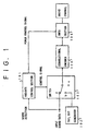
- Figure 1 is a block diagram showing a structure of a transmitter section for a mobile radio communication system according to a preferred embodiment of the present invention;
- Figures 2A and 2B are diagrams, respectively, for explaining an insertion manner of tail bits relative to input sound data according to the preferred embodiment;
- Figure 3 is a flowchart representing an operation of a VAD/DTX control section shown in Fig. 1;
- Fig. 4 is a block diagram showing a structure of a receiver section corresponding to the transmitter section shown in Fig. 1. according to a preferred embodiment of the present invention; and
- Fig. 5 is a block diagram showing a structure of a receiver section corresponding to the transmitter section shown in Fig. 1. according to another preferred embodiment of the present invention.
-
- Now, preferred embodiments of the present invention will be described hereinbelow with reference to the accompanying drawings.
- Before describing the preferred embodiments, brief explanation will be given hereinbelow about the VAD/DTX control and the Viterbi decoding which are employed in the following preferred embodiments.
- The VAD/DTX control is used in the communication system for transmitting/receiving sound data. In the VAD/DTX control, data to be transmitted is monitored for detection of a soundless or sound-absent section in the data. When the soundless section is detected, a transmission power for that soundless section is lowered to 0 (zero) or a given value other than 0. Accordingly, in the mobile radio communication system using the VAD/DTX control, a power consumption is diminished at a transmitter side, while, at a receiver side, interference to other ongoing communications can be suppressed.
- On the other hand, the Viterbi decoding is the optimum decoding method for the convolutional code and thus can easily achieve decoding of the convolutional code which is otherwise difficult to decode using the other decoding methods. Specifically, in the Viterbi decoding, a codeword which is the closest to an input string in terms of the Hamming distance is selected and outputted as a result of the decoding. For enhancing convergence or reliability of the Viterbi decoding, it is necessary to insert tail bits per unit, such as, per frame of data or a data bit stream.
- In consideration of the foregoing advantages of the VAD/DTX control and the Viterbi decoding, the mobile radio communication system having both advantages or functions has been sought. However, as described above, the Viterbi decoding requires the tail bits to be inserted to the data bit stream per unit. Conventionally, this process was dealt with by changing a data transmission rate. As a result, in the system using the Viterbi decoding, the hardware structure for generating clock pulses inevitably becomes complicated.
- The following preferred embodiments aim to provide the mobile radio communication system which employs the VAD/DTX control and the Viterbi decoding, while is free of the foregoing drawbacks.
- Fig. 1 shows a transmitter section in the mobile radio communication system according to a preferred embodiment of the present invention. The transmitter section shown in Fig. 1 may be used as a transmitter section of a mobile station and/or a base station for, such as, the personal communication system or the digital cellular system.
- In Fig. 1, a VAD/DTX control section 101 is connected to an input data line for receiving input sound data therefrom. The VAD/DTX control section 101 monitors the received input sound data for detection of sound contained in the input sound data. The VAD/DTX control section 101 controls operations of a switch 103 and a
transmitting section 105 depending on a result of the sound detection. Specifically, when sound is detected in the input sound data, the VAD/DTX control section 101 controls the switch 103 to connect aconvolutional encoder 104 to the input data line. The VAD/DTX control section 101 further performs a power control of atransmitting section 105 to allow transmission of the input sound data on a radio channel. - A tail bit generator 102 is connected to an input side of the switch 103 and produces given tail bits. On the other hand, the
convolutional encoder 104 is connected to an output side of the switch 103. Theconvolutional encoder 104 convolutionally encodes the input sound data or the tail bits fed through the switch 103 for error correction at a receiver side. - The switch 103 has three input terminals a, b and c and connects the
convolutional encoder 104 to one of the three input terminals under the control of the VAD/DTX control section 101. The input terminal a is connected to the input data line, the input terminal b is connected to the tail bit generator 102, and the input terminal c is grounded. - Figs. 2A and 2B are diagrams, respectively, for explaining an insertion manner of the tail bits relative to the input sound data. Fig. 2B shows the input sound data. As appreciated from Fig. 2A, in this preferred embodiment, the tail bits, which may be eight "0" bits, are added immediately after each of sound-present sections of the input sound data which are divided by subsequent soundless or sound-absent sections. The tail bit-added data shown in Fig. 2A are transmitted from the transmitting
section 105 on the radio channel. - Fig. 3 is a flowchart showing a control routine to be executed by the VAD/DTX control section 101.
- In Fig. 3, at step 301, it is assumed that a sound-present section of the input sound data is now detected so that the data transmission is performed at the transmitting
section 105. At this time, the input terminal a is connected to the output terminal in the switch 103. Subsequently, atstep 302, the VAD/DTX control section 101 determines whether a sound-absent section is detected. If answer is negative, the routine returns to step 301 where the input terminal a is held to be connected to the output terminal in the switch 103. On the other hand, if answer atstep 302 is positive, that is, the sound-absent section is detected, the routine proceeds to step 303 where the input terminal b is connected to the output terminal in the switch 103 so that the transmission of the sound data is stopped, and instead, the tail bits (a string of eight "0" bits in this preferred embodiment) produced by the tail bit generator 102 are fed to thetransmitting section 105 via theconvolutional encoder 104 so as to be transmitted on the radio channel. - Subsequently, the routine proceeds to step 304 where the VAD/DTX control section 101 determines whether a sound-absent section is detected. If answer at
step 304 is negative, that is, a sound-present section is detected, the input terminal a is connected to transmit the input sound data at step 301. On the other hand, if answer atstep 304 is positive, the routine proceeds to step 305 where the VAD/DTX control section 101 control the switch 103 to connect the input terminal c to the output terminal and further performs the power control to reduce the power to thetransmitting section 105 to 0 (zero). Accordingly, no transmission is allowed from the transmittingsection 105. The execution ofsteps step 304 becomes negative. - It may be arranged that, at
step 305, the transmission power is lowered to a given value other than 0. In this case, instead of connecting the input terminal c, the input terminal a is connected to the output terminal in the switch 103. - The sound data and the tail bits convolutionally encoded by the
convolutional encoder 104 are modulated at the transmittingsection 105 and sent out on the radio channel as modulated sound- indicative data. The modulated sound-indicative data are received by the receiver side and demodulated. The demodulated sound-indicative data are decoded by a Viterbi decoder at the receiver side so as to be outputted as decoded data. - It may be arranged that a communication control signal or the like is transmitted along with the above-noted modulated sound-indicative data.
- Fig. 4 is a block diagram showing a structure of a receiver section corresponding to the transmitter section shown in Fig. 1. according to a preferred embodiment of the present invention. In this preferred embodiment, the transmitter section shown in Fig. 1 transmits signaling data for the communication control protocol along with the foregoing modulated sound-indicative data. The signaling data represent ON/OFF information about the transmission power of the sound-indicative data.
- In Fig. 4, the receiver section includes a receiving section 401 for receiving signals from the radio channels, a
Viterbi decoder 402, a sound decoder 403 and a control section 404. The receiving section 401 separates the sound-indicative data including the sound data and the tail bits, and the signaling data from the signals received from the radio channels, and outputs the sound-indicative data to theViterbi decoder 402 and the signaling data to the control section 404. TheViterbi decoder 402 decodes the sound-indicative data to derive decoded data and outputs the decoded data to the sound decoder 403. The sound decoder 403 converts the received decoded data to sound data and outputs same. - The control section 404 operates based on the received signaling data, that is, the ON/OFF information about the transmission power caused by the VAD/DTX control. Specifically, when the OFF information is received, the control section 404 sends an OFF control signal to each of the receiving section 401, the
Viterbi decoder 402 and the sound decoder 403. In response to the OFF control signal, the receiving section 401 stops sending the sound-indicative data to theViterbi decoder 402 so that the operation of theViterbi decoder 402 is stopped. The sound decoder 403 outputs, as sound data, ambient noise as represented by Hoth noise. - On the other hand, when the ON information is received, the control section 404 sends an ON control signal to each of the receiving section 401, the
Viterbi decoder 402 and the sound decoder 403. In response to the ON control signal, the receiving section 401 sends the sound-indicative data to theViterbi decoder 402 so that theViterbi decoder 402 starts the operation. The sound decoder 403 stops the foregoing ambient noise and decodes the decoded data into the sound data. - Fig. 5 is a block diagram showing a structure of a receiver section corresponding to the transmitter section shown in Fig. 1, according to another preferred embodiment of the present invention. In this preferred embodiment, the transmitter section shown in Fig. 1 transmits pilot signals for detection of signal synchronization and phase rotation along with the sound-indicative data.
- In this preferred embodiment, the receiver section also includes a receiving section 501, a
Viterbi decoder 502, asound decoder 503 and a control section 504. - The receiving section 501 sends the sound-indicative data to the
Viterbi decoder 502 and received-power information to the control section 504. The received-power information is a ratio of a received power of the signal representing the sound-indicative data relative to a received power of the pilot signal. Accordingly, it represents a large value at the sound-present section and a smaller value at the sound-absent section. TheViterbi decoder 502 sends decoded data to thesound decoder 503 and a state of internal registers of theViterbi decoder 502 to the control section 504. Thesound decoder 503 converts the received decoded data into sound data. - The control section 504 determines the sound-present section or the sound-absent section based on the received-power information and the internal register state of the
Viterbi decoder 502. In this preferred embodiment, the control section 504 determines the sound-absent section when the internal register state corresponds to the tail bits and the received-power information becomes equal to or smaller than a given threshold value. - When the sound-absent section is determined, the control section 504 sends an OFF control signal to each of the receiving section 501, the
Viterbi decoder 502 and thesound decoder 503. In response to the OFF control signal, the receiving section stops sending the sound-indicative data to theViterbi decoder 502 so that theViterbi decoder 502 stops the operation. At this time, thesound decoder 503 outputs, as sound data, ambient noise as represented by Hoth noise. - On the other hand, when the sound-present section is determined, the control section 504 sends an ON control signal to each of the receiving section 501, the
Viterbi decoder 502 and thesound decoder 503. In response to the ON control signal, the receiving section 501 sends the sound-indicative data to theViterbi decoder 502 so that the Viterbi decoder starts the operation. Accordingly, thesound decoder 503 stops outputting the ambient noise and decodes the received decoded data into the sound data. - As described above, according to the foregoing preferred embodiments, the tail bits are not inserted per frame as in the prior art. Specifically, when the sound-absent section is detected, the transmission of the sound data is stopped, and instead, the tail bits are transmitted. The transmission power is lowered to 0 (zero) or the given value other than 0 when the transmission of the tail bits is finished. Accordingly, error-correction capability of the convolutional code is not deteriorated by the VAD/DTX control. Further, it is not necessary to change the transmission rate of the sound data so that the complication of the hardware structure for generating clock pulses is prevented. Specifically, a temporary shunt memory, a switching circuit and a plurality of clock circuits which have been conventionally required for the rate matching can be replaced only by a switching circuit.
- Further, by performing the VAD/DTX control, the transmission power consumption at the transmitter side as well as the power consumption for the decoding process to derive the sound data at the receiver side can be lowered, and further, the interference in the radio channels can be suppressed. Accordingly, the reduction in size and weight of the mobile station can be realized with the good communication quality.
Claims (21)
- A transmitter section for a mobile radio communication, comprising:characterised in that said discontinuous transmission control section (101) is arranged to control said switching section (103) to insert said tail bits at sound-absent sections immediately following a sound-present section and to further control the transmission power to be lowered for subsequent sound-absent sections until another sound-present section is detected.a discontinuous transmission control section (101) for detecting sound-present sections and sound-absent sections in sound data to be transmitted on a radio channel and for lowering the transmission power for said sound-absent sections;a tail bit generator (102) for generating predetermined tail bits to be inserted at sound-absent sections;a switching section (103) for inputting either said sound data or said tail bits into a convolutional encoder; anda convolutional encoder (104) for convolutionally encoding said sound data or said tail bits for error correction;
- The transmitter section as set forth in claim 1, wherein said discontinuous transmission control section (101) controls the transmission power to 0 for said sound-absent section where no tail bits are inserted.
- The transmitter section as set forth in claim 1, wherein said transmitter section is adapted for the Viterbi decoding.
- The transmitter section as set forth in claim 1, wherein said transmitter section is applied to a mobile station.
- The transmitter section as set forth in claim 1, wherein said transmitter section is applied to a base station.
- The transmitter section as set forth in claim 1, wherein said switching section (103) includes a first terminal for inputting said sound data, a second terminal for inputting said tail bits from said tail bit generator, and a third terminal, and wherein said third terminal is connected to said convolutional encoder (104) at said sound-absent section where no tail bits are inserted.
- A discontinuous transmission control method adapted for Viterbi decoding in a mobile radio communication, said method comprising the steps of:inputting sound data;detecting sound-present sections and sound-absent sections in the sound data to be transmitted on a radio channel;generating predetermined tail bits to be inserted at said sound-absent section;inserting said tail bits at sound-absent sections immediately following a sound-present section when detecting a sound-absent section in the sound data after a sound-present section;inputting either the sound data or the tail bits into a convolutional encoder; and convolutionally encoding the input sound data or the input tail bits for error correction;the method being characterised by lowering the transmission power for subsequent sound-absent sections until another sound-present section is detected.
- A receiver section for a mobile radio communication, comprising:wherein said control section (404, 504), in response to the power information, stops said receiving section (401, 501) from sending said sound-indicative data to said first decoder (402, 502) and stops said first decoder (402, 502) from converting said sound-indicative data into said decoded data, while allowing said second decoder (403, 503) to output ambient noise instead of said sound data, and wherein said control section (404, 504), in response to the power information, allows said receiving section (401, 501) to send said sound-indicative data to said first decoder (402, 502) and allows said first decoder (402, 502) to convert said sound-indicative data into said decoded data so that said second decoder (403, 503) converts said decoded data inputted from said first decoder (402, 502) into said sound data.a receiving section (401, 501) for separating sound-indicative data and a power information of the sound-indicative data from data transmitted on a radio channel and outputting said sound-indicative data and said power information;a first decoder (402, 502) for inputting said sound indicative data from said receiving section (401, 501) to convert said sound-indicative data into decoded data;a second decoder (403, 503) for inputting said decoded data from said first decoder (402, 502) and for converting said decoded data into sound data; anda control section (404, 504) for inputting said power information from said receiving section (401, 501) to control said receiving section (401, 501), said first decoder (402, 502) and said second decoder (403, 503),
- The receiver section as set forth in claim 8, wherein said power information comprises signalling data representing ON/OFF information about transmission power of the sound indicative data.
- The receiver section as set forth in claim 8, wherein said power information comprises pilot signals for detection of signal synchronisation and phase rotation.
- The receiver section as set forth in claim 10, including means for deriving received-power information as a ratio of the received power of the sound indicative data relative to the received power of the pilot signals.
- The receiver section as set forth in claim 11, wherein said first decoder further detects tail bits contained in said sound-indicative data and the result of said tail bit detection is input into said control section to determine a sound-absent section or a sound-present section in said sound indicative data, based on said received-power information and said tail bit detection result.
- The receiver section as set forth in any one of claims 8 to 12, wherein said first decoder (402, 502) is a Viterbi decoder.
- The receiver section as set forth in claim 8, wherein said ambient noise is Hoth noise.
- The receiver section as set forth in claim 8, wherein said receiver section is applied to a mobile station.
- The receiver section as set forth in claim 8, wherein said receiver section is applied to a base station.
- A mobile radio communication system comprising:wherein said control section (404, 504), in response to the power information, stops said receiving section (401, 501) from sending said sound-indicative data to said first decoder (402, 502) and stops said first decoder (402, 502) from converting said sound-indicative data into said decoded data, while allowing said second decoder (403, 503) to output ambient noise instead of said sound data, and wherein said control section (404, 504), in response to the power information, allows said receiving section (401, 501) to send said sound-indicative data to said first decoder (402, 502) and allows said first decoder (402, 502) to convert said sound-indicative data into said decoded data so that said second decoder (403, 503) converts said decoded data inputted from said first decoder (402, 502) into said sound data.a base station includinga transmitter section includinga discontinuous transmission control section (101) for detecting sound-present sections and sound-absent sections in sound data to be transmitted on a radio channel and for lowering the transmission power for said sound-absent sections;a tail bit generator (102) for generating predetermined tail bits to be inserted at sound-absent sections;a switching section (103) for inputting either said sound data or said tail bits into a convolutional encoder; anda convolutional encoder (104) for convolutionally encoding said sound data or said tail bits for error correction;wherein said discontinuous transmission control section (101) is arranged to control said switching section (103) to insert said tail bits at sound-absent sections immediately following a sound-present section and to further control the transmission power to be lowered for subsequent sound-absent sections until another sound-present section is detected;a receiver section includinga receiving section (401, 501) for separating sound-indicative data and a power information of the sound-indicative data from data transmitted on a radio channel and outputting said sound-indicative data and said power information;a first decoder (402, 502) for inputting said sound indicative data from said receiving section (401, 501) to convert said sound-indicative data into decoded data;a second decoder (403, 503) for inputting said decoded data from said first decoder (402, 502) and for converting said decoded data into sound data; anda control section (404, 504) for inputting said power information from said receiving section (401, 501) to control said receiving section (401, 501), said first decoder (402, 502) and said second decoder (403, 503),wherein said control section (404, 504), in response to the power information, stops said receiving section (401, 501) from sending said sound-indicative data to said first decoder (402, 502) and stops said first decoder (402, 502) from converting said sound-indicative data into said decoded data, while allowing said second decoder (403, 503) to output ambient noise instead of said sound data, and wherein said control section (404, 504), in response to the power information, allows said receiving section (401, 501) to send said sound-indicative data to said first decoder (402, 502) and allows said first decoder (402, 502) to convert said sound-indicative data into said decoded data so that said second decoder (403, 503) converts said decoded data inputted from said first decoder (402, 502) into said sound data;a mobile station includinga transmitter section includinga discontinuous transmission control section (101) for detecting sound-present sections and sound-absent sections in sound data to be transmitted on a radio channel and for lowering the transmission power for said sound-absent sections;a tail bit generator (102) for generating predetermined tail bits to be inserted at sound-absent sections;a switching section (103) for inputting either said sound data or said tail bits into a convolutional encoder; anda convolutional encoder (104) for convolutionally encoding said sound data or said tail bits for error correction;wherein said discontinuous transmission control section (101) is arranged to control said switching section (103) to insert said tail bits at sound-absent sections immediately following a sound-present section and to further control the transmission power to be lowered for subsequent sound-absent sections until another sound-present section is detecteda receiver section includinga receiving section (401, 501) for separating sound-indicative data and a power information of the sound-indicative data from data transmitted on a radio channel and outputting said sound-indicative data and said power information;a first decoder (402, 502) for inputting said sound indicative data from said receiving section (401, 501) to convert said sound-indicative data into decoded data;a second decoder (403, 503) for inputting said decoded data from said first decoder (402, 502) and for converting said decoded data into sound data; anda control section (404, 504) for inputting said power information from said receiving section (401, 501) to control said receiving section (401, 501), said first decoder (402, 502) and said second decoder (403, 503),
- The system as set forth in claim 17, wherein said power information comprises signalling data representing ON/OFF information about transmission power of the sound indicative data.
- The system as set forth in claim 17, wherein said power information comprises pilot signals for detection of signal synchronisation and phase rotation.
- The system as set forth in claim 19, including means for deriving received-power information as a ratio of the received power of the sound indicative data relative to the received power of the pilot signals.
- The system as set forth in claim 20, wherein said first decoder (402, 502) further detects tail bits contained in said sound-indicative data and the result of said tail bit detection is input into said control section to determine a sound-absent section or a sound-present section in said sound indicative data, based on said received-power information and said tail bit detection result.
Applications Claiming Priority (3)
| Application Number | Priority Date | Filing Date | Title |
|---|---|---|---|
| JP91914/94 | 1994-04-28 | ||
| JP06091914A JP3090842B2 (en) | 1994-04-28 | 1994-04-28 | Transmitter adapted to Viterbi decoding method |
| JP9191494 | 1994-04-28 |
Publications (2)
| Publication Number | Publication Date |
|---|---|
| EP0680034A1 EP0680034A1 (en) | 1995-11-02 |
| EP0680034B1 true EP0680034B1 (en) | 2002-07-24 |
Family
ID=14039860
Family Applications (1)
| Application Number | Title | Priority Date | Filing Date |
|---|---|---|---|
| EP95302750A Expired - Lifetime EP0680034B1 (en) | 1994-04-28 | 1995-04-25 | Mobile radio communication system using a sound or voice activity detector and convolutional coding |
Country Status (5)
| Country | Link |
|---|---|
| US (1) | US5694429A (en) |
| EP (1) | EP0680034B1 (en) |
| JP (1) | JP3090842B2 (en) |
| KR (1) | KR100262414B1 (en) |
| DE (1) | DE69527470T2 (en) |
Cited By (1)
| Publication number | Priority date | Publication date | Assignee | Title |
|---|---|---|---|---|
| US9190066B2 (en) | 1998-09-18 | 2015-11-17 | Mindspeed Technologies, Inc. | Adaptive codebook gain control for speech coding |
Families Citing this family (15)
| Publication number | Priority date | Publication date | Assignee | Title |
|---|---|---|---|---|
| FI961567A (en) * | 1996-04-10 | 1997-10-11 | Nokia Telecommunications Oy | Noise suppression in an analog mobile communication system |
| CA2208660C (en) * | 1996-07-19 | 2002-09-17 | Takashi Suzuki | Data transmission device |
| US5954834A (en) * | 1996-10-09 | 1999-09-21 | Ericsson Inc. | Systems and methods for communicating desired audio information over a communications medium |
| DE19716862A1 (en) * | 1997-04-22 | 1998-10-29 | Deutsche Telekom Ag | Voice activity detection |
| DE19730984A1 (en) * | 1997-07-18 | 1999-02-11 | Siemens Ag | Radio transmission method and cordless telephone, especially for the DECT standard |
| KR100387078B1 (en) * | 1997-07-30 | 2003-10-22 | 삼성전자주식회사 | Apparatus and method for puncturing and recovering symbol in band-spreading communication system |
| US5897613A (en) * | 1997-10-08 | 1999-04-27 | Lucent Technologies Inc. | Efficient transmission of voice silence intervals |
| US6256606B1 (en) | 1998-11-30 | 2001-07-03 | Conexant Systems, Inc. | Silence description coding for multi-rate speech codecs |
| DE10055658B4 (en) * | 2000-11-10 | 2004-04-29 | Infineon Technologies Ag | Method and circuit for synchronizing a receiver for a convolutionally coded received signal |
| US6980838B2 (en) * | 2001-05-10 | 2005-12-27 | Motorola, Inc. | Control channel to enable a low power mode in a wideband wireless communication system |
| GB2396271B (en) * | 2002-12-10 | 2005-08-10 | Motorola Inc | A user terminal and method for voice communication |
| US7877674B2 (en) * | 2006-07-25 | 2011-01-25 | Broadcom Corporation | Method and system for redundancy-based decoding of voice content in a wireless LAN system |
| CN100555414C (en) * | 2007-11-02 | 2009-10-28 | 华为技术有限公司 | A kind of DTX decision method and device |
| CN101335000B (en) * | 2008-03-26 | 2010-04-21 | 华为技术有限公司 | Method and apparatus for encoding |
| JP7071579B1 (en) * | 2021-10-27 | 2022-05-19 | アルインコ株式会社 | Digital wireless transmitters and digital wireless communication systems |
Family Cites Families (7)
| Publication number | Priority date | Publication date | Assignee | Title |
|---|---|---|---|---|
| CA2020899C (en) * | 1989-08-18 | 1995-09-05 | Nambirajan Seshadri | Generalized viterbi decoding algorithms |
| JP2877375B2 (en) * | 1989-09-14 | 1999-03-31 | 株式会社東芝 | Cell transfer method using variable rate codec |
| US5659569A (en) * | 1990-06-25 | 1997-08-19 | Qualcomm Incorporated | Data burst randomizer |
| GB2256351B (en) * | 1991-05-25 | 1995-07-05 | Motorola Inc | Enhancement of echo return loss |
| JP2776094B2 (en) * | 1991-10-31 | 1998-07-16 | 日本電気株式会社 | Variable modulation communication method |
| JPH06244878A (en) * | 1993-02-18 | 1994-09-02 | Fujitsu Ltd | Modem |
| US5559832A (en) * | 1993-06-28 | 1996-09-24 | Motorola, Inc. | Method and apparatus for maintaining convergence within an ADPCM communication system during discontinuous transmission |
-
1994
- 1994-04-28 JP JP06091914A patent/JP3090842B2/en not_active Expired - Fee Related
-
1995
- 1995-02-24 KR KR1019950003689A patent/KR100262414B1/en not_active IP Right Cessation
- 1995-04-21 US US08/426,253 patent/US5694429A/en not_active Expired - Lifetime
- 1995-04-25 DE DE69527470T patent/DE69527470T2/en not_active Expired - Lifetime
- 1995-04-25 EP EP95302750A patent/EP0680034B1/en not_active Expired - Lifetime
Cited By (2)
| Publication number | Priority date | Publication date | Assignee | Title |
|---|---|---|---|---|
| US9190066B2 (en) | 1998-09-18 | 2015-11-17 | Mindspeed Technologies, Inc. | Adaptive codebook gain control for speech coding |
| US9269365B2 (en) | 1998-09-18 | 2016-02-23 | Mindspeed Technologies, Inc. | Adaptive gain reduction for encoding a speech signal |
Also Published As
| Publication number | Publication date |
|---|---|
| DE69527470T2 (en) | 2003-03-20 |
| US5694429A (en) | 1997-12-02 |
| JP3090842B2 (en) | 2000-09-25 |
| DE69527470D1 (en) | 2002-08-29 |
| KR100262414B1 (en) | 2000-08-01 |
| EP0680034A1 (en) | 1995-11-02 |
| KR950035110A (en) | 1995-12-30 |
| JPH07297782A (en) | 1995-11-10 |
Similar Documents
| Publication | Publication Date | Title |
|---|---|---|
| EP0680034B1 (en) | Mobile radio communication system using a sound or voice activity detector and convolutional coding | |
| AU717697B2 (en) | A method for frame quality detection and a receiver | |
| JPH08130775A (en) | Digital cordless telephone system | |
| US5802076A (en) | Audio error mitigation technique for a TDMA communication system | |
| KR100300688B1 (en) | Method and apparatus for providing a multi-party speech connection for use in a wireless communication system | |
| JP2007074751A (en) | Transmission method for transmitting signals between first and second communication networks, mobile station, and mobile communication system | |
| US5559832A (en) | Method and apparatus for maintaining convergence within an ADPCM communication system during discontinuous transmission | |
| JPH1079981A (en) | Voice recording method in mobile communication device and mobile communication device | |
| EP0931310B1 (en) | Systems and methods for communicating desired audio information over a communications medium | |
| JPH0759030A (en) | Video conference system | |
| JP3249457B2 (en) | Voice transmission / reception equipment for digital communication | |
| EP0552781A2 (en) | Voice signal communication with burst error reduction | |
| JPH0661903A (en) | Talking device | |
| JP3947876B2 (en) | Data transmission system and method using PCM code | |
| JPH09139980A (en) | Receiver | |
| US8055980B2 (en) | Error processing of user information received by a communication network | |
| JP3120836B2 (en) | CODEC1 link control method and CODEC1 link connection control base station | |
| JPH05327666A (en) | Digital data communication system | |
| US7242672B2 (en) | System and method for formatting voice data in a mobile telecommunication system | |
| JP2705442B2 (en) | Synchronous method | |
| JPH11127485A (en) | Voice/data simultaneous transmission system | |
| JPH0774733A (en) | Digital radio telephone set | |
| JPH0417421A (en) | Dsi device | |
| JPS61274534A (en) | Voice transmission system | |
| JPH06237238A (en) | In channel signaling transmission method |
Legal Events
| Date | Code | Title | Description |
|---|---|---|---|
| PUAI | Public reference made under article 153(3) epc to a published international application that has entered the european phase |
Free format text: ORIGINAL CODE: 0009012 |
|
| AK | Designated contracting states |
Kind code of ref document: A1 Designated state(s): DE FR GB |
|
| 17P | Request for examination filed |
Effective date: 19960223 |
|
| 17Q | First examination report despatched |
Effective date: 19990118 |
|
| GRAG | Despatch of communication of intention to grant |
Free format text: ORIGINAL CODE: EPIDOS AGRA |
|
| RIC1 | Information provided on ipc code assigned before grant |
Free format text: 7G 10L 11/02 A, 7G 10L 19/00 B, 7H 03M 13/23 B, 7H 04J 3/16 B, 7H 04L 1/00 B |
|
| GRAG | Despatch of communication of intention to grant |
Free format text: ORIGINAL CODE: EPIDOS AGRA |
|
| GRAH | Despatch of communication of intention to grant a patent |
Free format text: ORIGINAL CODE: EPIDOS IGRA |
|
| GRAH | Despatch of communication of intention to grant a patent |
Free format text: ORIGINAL CODE: EPIDOS IGRA |
|
| GRAA | (expected) grant |
Free format text: ORIGINAL CODE: 0009210 |
|
| AK | Designated contracting states |
Kind code of ref document: B1 Designated state(s): DE FR GB |
|
| REG | Reference to a national code |
Ref country code: GB Ref legal event code: FG4D |
|
| REF | Corresponds to: |
Ref document number: 69527470 Country of ref document: DE Date of ref document: 20020829 |
|
| ET | Fr: translation filed | ||
| PLBE | No opposition filed within time limit |
Free format text: ORIGINAL CODE: 0009261 |
|
| STAA | Information on the status of an ep patent application or granted ep patent |
Free format text: STATUS: NO OPPOSITION FILED WITHIN TIME LIMIT |
|
| 26N | No opposition filed |
Effective date: 20030425 |
|
| REG | Reference to a national code |
Ref country code: GB Ref legal event code: 732E |
|
| REG | Reference to a national code |
Ref country code: FR Ref legal event code: TP |
|
| PGFP | Annual fee paid to national office [announced via postgrant information from national office to epo] |
Ref country code: GB Payment date: 20140414 Year of fee payment: 20 |
|
| PGFP | Annual fee paid to national office [announced via postgrant information from national office to epo] |
Ref country code: DE Payment date: 20140430 Year of fee payment: 20 Ref country code: FR Payment date: 20140428 Year of fee payment: 20 |
|
| REG | Reference to a national code |
Ref country code: DE Ref legal event code: R071 Ref document number: 69527470 Country of ref document: DE |
|
| REG | Reference to a national code |
Ref country code: GB Ref legal event code: PE20 Expiry date: 20150424 |
|
| PG25 | Lapsed in a contracting state [announced via postgrant information from national office to epo] |
Ref country code: GB Free format text: LAPSE BECAUSE OF EXPIRATION OF PROTECTION Effective date: 20150424 |