EP0679549A1 - Head-up displaying device for a vehicle - Google Patents
Head-up displaying device for a vehicle Download PDFInfo
- Publication number
- EP0679549A1 EP0679549A1 EP95102276A EP95102276A EP0679549A1 EP 0679549 A1 EP0679549 A1 EP 0679549A1 EP 95102276 A EP95102276 A EP 95102276A EP 95102276 A EP95102276 A EP 95102276A EP 0679549 A1 EP0679549 A1 EP 0679549A1
- Authority
- EP
- European Patent Office
- Prior art keywords
- head
- case
- combiner
- displaying device
- image
- Prior art date
- Legal status (The legal status is an assumption and is not a legal conclusion. Google has not performed a legal analysis and makes no representation as to the accuracy of the status listed.)
- Granted
Links
- 239000011521 glass Substances 0.000 claims abstract description 6
- 238000000576 coating method Methods 0.000 claims abstract description 5
- 230000003287 optical effect Effects 0.000 claims description 10
- 239000004973 liquid crystal related substance Substances 0.000 claims description 6
- 239000011248 coating agent Substances 0.000 claims description 2
- 239000012260 resinous material Substances 0.000 abstract 1
- 238000009434 installation Methods 0.000 description 3
- 230000002708 enhancing effect Effects 0.000 description 2
- NIXOWILDQLNWCW-UHFFFAOYSA-N acrylic acid group Chemical group C(C=C)(=O)O NIXOWILDQLNWCW-UHFFFAOYSA-N 0.000 description 1
- 230000015572 biosynthetic process Effects 0.000 description 1
- 238000010586 diagram Methods 0.000 description 1
- 239000000428 dust Substances 0.000 description 1
- 230000010354 integration Effects 0.000 description 1
- 238000004519 manufacturing process Methods 0.000 description 1
- XLYOFNOQVPJJNP-UHFFFAOYSA-N water Substances O XLYOFNOQVPJJNP-UHFFFAOYSA-N 0.000 description 1
Images


Classifications
-
- G—PHYSICS
- G02—OPTICS
- G02B—OPTICAL ELEMENTS, SYSTEMS OR APPARATUS
- G02B27/00—Optical systems or apparatus not provided for by any of the groups G02B1/00 - G02B26/00, G02B30/00
- G02B27/01—Head-up displays
- G02B27/0149—Head-up displays characterised by mechanical features
-
- B60K35/60—
-
- B—PERFORMING OPERATIONS; TRANSPORTING
- B60—VEHICLES IN GENERAL
- B60Q—ARRANGEMENT OF SIGNALLING OR LIGHTING DEVICES, THE MOUNTING OR SUPPORTING THEREOF OR CIRCUITS THEREFOR, FOR VEHICLES IN GENERAL
- B60Q1/00—Arrangement of optical signalling or lighting devices, the mounting or supporting thereof or circuits therefor
- B60Q1/26—Arrangement of optical signalling or lighting devices, the mounting or supporting thereof or circuits therefor the devices being primarily intended to indicate the vehicle, or parts thereof, or to give signals, to other traffic
- B60Q1/30—Arrangement of optical signalling or lighting devices, the mounting or supporting thereof or circuits therefor the devices being primarily intended to indicate the vehicle, or parts thereof, or to give signals, to other traffic for indicating rear of vehicle, e.g. by means of reflecting surfaces
- B60Q1/302—Arrangement of optical signalling or lighting devices, the mounting or supporting thereof or circuits therefor the devices being primarily intended to indicate the vehicle, or parts thereof, or to give signals, to other traffic for indicating rear of vehicle, e.g. by means of reflecting surfaces mounted in the vicinity, e.g. in the middle, of a rear window
-
- G—PHYSICS
- G02—OPTICS
- G02B—OPTICAL ELEMENTS, SYSTEMS OR APPARATUS
- G02B27/00—Optical systems or apparatus not provided for by any of the groups G02B1/00 - G02B26/00, G02B30/00
- G02B27/01—Head-up displays
-
- G—PHYSICS
- G02—OPTICS
- G02B—OPTICAL ELEMENTS, SYSTEMS OR APPARATUS
- G02B27/00—Optical systems or apparatus not provided for by any of the groups G02B1/00 - G02B26/00, G02B30/00
- G02B27/01—Head-up displays
- G02B27/0101—Head-up displays characterised by optical features
-
- G—PHYSICS
- G02—OPTICS
- G02B—OPTICAL ELEMENTS, SYSTEMS OR APPARATUS
- G02B27/00—Optical systems or apparatus not provided for by any of the groups G02B1/00 - G02B26/00, G02B30/00
- G02B27/01—Head-up displays
- G02B27/0101—Head-up displays characterised by optical features
- G02B2027/0118—Head-up displays characterised by optical features comprising devices for improving the contrast of the display / brillance control visibility
-
- G—PHYSICS
- G02—OPTICS
- G02B—OPTICAL ELEMENTS, SYSTEMS OR APPARATUS
- G02B27/00—Optical systems or apparatus not provided for by any of the groups G02B1/00 - G02B26/00, G02B30/00
- G02B27/01—Head-up displays
- G02B27/0149—Head-up displays characterised by mechanical features
- G02B2027/0154—Head-up displays characterised by mechanical features with movable elements
- G02B2027/0156—Head-up displays characterised by mechanical features with movable elements with optionally usable elements
-
- G—PHYSICS
- G02—OPTICS
- G02B—OPTICAL ELEMENTS, SYSTEMS OR APPARATUS
- G02B27/00—Optical systems or apparatus not provided for by any of the groups G02B1/00 - G02B26/00, G02B30/00
- G02B27/01—Head-up displays
- G02B27/0179—Display position adjusting means not related to the information to be displayed
- G02B2027/0181—Adaptation to the pilot/driver
-
- G—PHYSICS
- G02—OPTICS
- G02B—OPTICAL ELEMENTS, SYSTEMS OR APPARATUS
- G02B27/00—Optical systems or apparatus not provided for by any of the groups G02B1/00 - G02B26/00, G02B30/00
- G02B27/01—Head-up displays
- G02B27/0179—Display position adjusting means not related to the information to be displayed
- G02B2027/0187—Display position adjusting means not related to the information to be displayed slaved to motion of at least a part of the body of the user, e.g. head, eye
-
- G—PHYSICS
- G02—OPTICS
- G02B—OPTICAL ELEMENTS, SYSTEMS OR APPARATUS
- G02B27/00—Optical systems or apparatus not provided for by any of the groups G02B1/00 - G02B26/00, G02B30/00
- G02B27/01—Head-up displays
- G02B2027/0192—Supplementary details
- G02B2027/0194—Supplementary details with combiner of laminated type, for optical or mechanical aspects
Definitions
- the present invention is related to a head-up displaying device for a vehicle.
- a conventional head-up display for a vehicle which is used to display vehicle speed or the like is schematically shown in Fig. 8.
- the head-up display according to the prior art comprises an image displaying unit 100 which includes an image projection unit 5 and a mirror (optical path) 7 therein.
- the image displaying unit 100 is installed inside a dashboard 2 of the vehicle and a combiner (reflecting member) 8 which is vapor-deposited on an inner surface of a windshield 200 to focus an image 17 ahead of the windshield 200.
- the primary object of the present invention is to provide a head-up displaying device for a vehicle which solves the above problems and can be installed more easily than prior art devices.
- Another object of the present invention is to provide a head-up displaying device in which a projecting unit, a reflecting member and a combiner are integrally secured to a suitable portion of a vehicle, and hence, the device may be formed as a unit.
- Another object of the present invention is to provide a head-up displaying device for a vehicle in which the combiner is foldable so that the device may be made compact.
- Still another object of the present invention is to provide a head-up displaying device for a vehicle in which the combiner may swing to adjust the position of the image as seen by the driver in the vertical direction.
- a further object of the present invention is to provide a head-up displaying device for a vehicle in which the combiner is rotatable to adjust the position of the image as seen by the driver in the horizontal direction.
- a still further object of the present invention is to provide a head-up displaying device for a vehicle in which the combiner includes a thin reflection hologram sheet enhancing the reflection efficiency of the device at a specific wavelength.
- a still further object of the present invention is to provide a head-up displaying device for a vehicle in which the aforementioned hologram has an aspherical concave lens disposed thereon to magnify the image viewed by the driver.
- a further object of the present invention is to provide a head-up displaying device for a vehicle in which the combiner includes an anti-reflection coating disposed on at least one side thereof to reduce undesired reflection and to provide a sharp image without double images.
- a still further object of the present invention is to provide a head-up displaying device for a vehicle in which an optical sensor for sensing the ambient light level and a controller automatically dimming the head-up display in response to the ambient light level are further provided to enhance visibility.
- Still another object of the present invention is to provide a head-up displaying device for a vehicle in which a main case housing the device includes a shade member to prevent the image projection unit from coming into the users field of vision.
- Still further object of the present invention is to provide a head-up displaying device for a vehicle in which a concave tray portion is formed at the upper surface of the device.
- a head-up displaying device 1 includes a base member 3 formed with a stem 3a and secured to a dashboard 2 of a vehicle close to an instrument panel (not shown), a main case 4 which is formed with a bottom plate 4a rotatably carried around the stem 3a of base member 3 and which houses an image projection unit 5, a control unit 6 and a reflecting member (mirror) 7 therein.
- a flat combiner 8 is foldably mounted on the upper portion of the main case 4.
- the base member 3 and the bottom plate 4a form a turn table rotatable horizontally with respect to the dashboard 2.
- the main case 4 has a cover 4c on which an opening 4b, a couple of openings 4e and a shade member 4d are formed.
- the shade member 4d blocks the image projection unit 5 housed in the main case 4 from the driver's line of sight.
- Image projection unit 5 is composed of a light source 5a, an optical lens 5b, a transmissive liquid crystal panel 5c and a case 5d to house these components.
- the case 5d is secured to the bottom plate 4a of the main case 4.
- the control unit 6 is secured to the bottom plate 4a of the main case 4.
- the reflecting member 7 is secured to the bottom plate 4a so that it faces the image projection unit 5, and is inclined relative to the bottom plate 4a at such an angle that an image beam may be reflected from the image projection unit 5 through the opening 4b to the surface of the combiner 8.
- the combiner 8 is held by a holder 9 at its lower end and is fitted into a groove 9a formed in the holder 9 and extending along the longitudinal direction thereof.
- the holder 9 rotates around a couple of shafts 9b formed on its sides and is secured to the cover 4c by a couple of clips 10.
- Each clip 10 has a pair of hooks 10a which hold a corresponding shaft 9b therebetween and is fitted into a corresponding hole 4e in cover 4c.
- the holder 9 functions as a hinge so that the combiner 8 may be raised or lowered as shown by the ghost view in Fig. 1.
- the combiner 8 When the combiner 8 is lowered, it covers the opening 4b to protect the interior of the displaying device 1 from dust, water and the like.
- the inclination angle of the combiner 8 may be adjusted as shown by lines ⁇ and ⁇ in Fig. 1 using the frictional retaining force of the clips 10 to catch the shafts 9b of the holder 9.
- the combiner 8 has a thin reflection hologram 13 which is formed with an aspherical concave lens (not shown) disposed thereon and is enclosed between glass panes 11 and 12 as shown in Fig. 3. Anti-reflection coatings 15 and 16 are also formed to cover the exposed surfaces of the combiner 8.
- the combiner 8 When head-up displaying device 1 described above is being used, the combiner 8 is first raised from the folded position. A light beam is emitted from light source 5a and passes through the optical lens 5b and the liquid crystal panel 5c which is controlled by control unit 6 to form an image pattern thereon. The light beam is then formed into a displaying image beam and projected out of the image projection unit 5 to the reflecting member 7, which reflects the displaying image beam to direct it to one side of the combiner 8 through the opening 4b. Then, the image is magnified by the aspherical lens formed on the combiner 8 into an image magnified several times over to focus a virtual image 17 in front of the other side of the combiner 8.
- the combiner 8 Since the image is magnified several times by the aspherical lens, a large-sized image may be obtained with a short optical length, which enables integration (unification) of the components of the device 1. Since the combiner 8 has anti-reflection coatings 15 and 16 formed thereon, light which is reflected by the sides of glass panes 12 and 14 may be reduced. Thus, the image light beam coming into the combiner 8 is substantially reflected by the hologram 13 so that the virtual image 17 is sharp without being doubled and also so that the driver can maintain an unobstructed view through the combiner 8. Since the combiner 8 has a thin sheet hologram enclosed therein, the reflection efficiency of the device 1 at its specific display wavelength may be enhanced.
- the driver wants to change the position of the image 17, it may be adjusted in the horizontal direction merely by rotating the main case 4 around the stem 3a of the base member 3 to an appropriate angle.
- the vertical position of the image 17 may also be adjusted by swinging the combiner 8 around the shafts 9b of the holder 9 to form an appropriate inclination angle. As a result, about 99% of the driver's field of vision may be preserved.
- the combiner 8 may be composed of resinous transparent plates 11, 12 and 13 such as acrylic plates in stead of the glass panes.
- the shafts 9b may be integrally formed on the sides of the resinous plates and, therefore, the combiner 8 and the holder 9 may be integrated into a unit, resulting in a reduction in the number of parts and the manufacturing cost and also resulting in an enhancing of the device's safety level.
- the liquid crystal panel 5c may be replaced by a self-illuminating image formation device such as a vacuum fluorescent display (VFD) or an electroluminescent panel (EL), in which case the light source 5a may be eliminated if appropriate.
- VFD vacuum fluorescent display
- EL electroluminescent panel
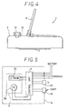
- Figs. 4 and 5 illustrate a structure of a head-up displaying device 1 for a vehicle according to the second embodiment of the invention, in which the main case 4 of the first embodiment further contains therein an optical sensor 18 and a dimmer knob 19 to provide control unit 6 with automatic dimmer control and manual dimmer control.
- Reference numerals in the figures for this embodiment generally used correspond to those in the figures of the first embodiment.
- the optical sensor 18 generates a signal in response to the ambient light level in the vicinity of the display image 17 and the dimmer knob 19 generates a signal for the control unit 6 to change the contrast or brightness of the display image 17 as desired by the driver.
- the control unit 6 is powered by a battery and controls the liquid crystal panel 5c to form image patterns in response to sigals sent thereto.
- the brightness adjustment may be made automatically in response to the ambient light conditions and, thereby, optimal visibility of the image is always assured. Further, a driver may manipulate the dimmer knob 19 as desired to adjust a desired brightness or contrast of the display image 17.
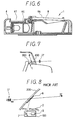
- FIG. 6 A third embodiment of the present invention is illustrated in Fig. 6 , in which the main case 4 of the first embodiment is formed with concave portions 4f and 8a on its cover 4c and on the back of the combiner 8, respectively. Such concave portions may be used for trays.
- a fourth embodiment of the head-up displaying device 1 according to the present invention is mounted on a rear panel 300 of the vehicle as illustrated in Fig. 7.
- This embodiment displays such information as brake signals or turn signals to other vehicles or persons behind the vehicle.
- the combiner 8 of the first embodiment additionally has a red colored member on its hologram 13 onto which light beams are projected in the same manner as in the first embodiment, so that a red three-dimensional image may come to the front of the combiner 8 and be projected through the rear windshield 400.
- the device 1 may be used for a high-position-mounted brake light.
Abstract
Description
- The present application is based on and claims the priority from Japanese patent application No. Hei 6-90054 filed on April 27, 1994, the content of which is incorporated herein by reference.
- The present invention is related to a head-up displaying device for a vehicle.
- A conventional head-up display for a vehicle which is used to display vehicle speed or the like is schematically shown in Fig. 8. The head-up display according to the prior art comprises an
image displaying unit 100 which includes animage projection unit 5 and a mirror (optical path) 7 therein. Theimage displaying unit 100 is installed inside adashboard 2 of the vehicle and a combiner (reflecting member) 8 which is vapor-deposited on an inner surface of awindshield 200 to focus animage 17 ahead of thewindshield 200. - However, such a conventional head-up displaying device for a vehicle has a separate
image projection unit 100 and aseparate combiner 8 and they must be separately installed in a vehicle. Therefore, such installation brings about a considerable increase in time-consuming work, resulting in high cost and difficulty of installation. - Therefore, the primary object of the present invention is to provide a head-up displaying device for a vehicle which solves the above problems and can be installed more easily than prior art devices.
- Another object of the present invention is to provide a head-up displaying device in which a projecting unit, a reflecting member and a combiner are integrally secured to a suitable portion of a vehicle, and hence, the device may be formed as a unit.
- Another object of the present invention is to provide a head-up displaying device for a vehicle in which the combiner is foldable so that the device may be made compact.
- Still another object of the present invention is to provide a head-up displaying device for a vehicle in which the combiner may swing to adjust the position of the image as seen by the driver in the vertical direction.
- A further object of the present invention is to provide a head-up displaying device for a vehicle in which the combiner is rotatable to adjust the position of the image as seen by the driver in the horizontal direction.
- A still further object of the present invention is to provide a head-up displaying device for a vehicle in which the combiner includes a thin reflection hologram sheet enhancing the reflection efficiency of the device at a specific wavelength.
- A still further object of the present invention is to provide a head-up displaying device for a vehicle in which the aforementioned hologram has an aspherical concave lens disposed thereon to magnify the image viewed by the driver.
- A further object of the present invention is to provide a head-up displaying device for a vehicle in which the combiner includes an anti-reflection coating disposed on at least one side thereof to reduce undesired reflection and to provide a sharp image without double images.
- A still further object of the present invention is to provide a head-up displaying device for a vehicle in which an optical sensor for sensing the ambient light level and a controller automatically dimming the head-up display in response to the ambient light level are further provided to enhance visibility.
- Still another object of the present invention is to provide a head-up displaying device for a vehicle in which a main case housing the device includes a shade member to prevent the image projection unit from coming into the users field of vision.
- Still further object of the present invention is to provide a head-up displaying device for a vehicle in which a concave tray portion is formed at the upper surface of the device.
- Other objects, features and characteristics of the present invention as well as the functions of related parts of the present invention will become clear from a study of the following detailed description, the appended claims and the drawings. In the drawings:
- Fig. 1 is a side cross-sectional view of a head-up displaying device according to the first embodiment of the present invention;
- Fig. 2 is an exploded-perspective view illustrating the connecting structure of a combiner and a main case of the first embodiment;
- Fig. 3 is a cross-sectional side view of the combiner shown in Fig. 2;
- Fig. 4 is a side view of a head-up displaying device for a vehicle according to the second embodiment of the present invention;
- Fig. 5 is a schematic circuit diagram of the above embodiment;
- Fig. 6 is a cross-sectional side view of a head-up displaying device for a vehicle according to the third embodiment of the present invention;
- Fig. 7 is a schematic view illustrating installation of a head-up displaying device for a vehicle according to the forth embodiment of the present invention; and
- Fig. 8 is a schematic view illustrating a conventional head-up displaying device.
-
- The preferred embodiments according to the present invention will be described as follows with reference to the appended drawings.
- As shown in Fig. 1, a head-up displaying device 1 includes a base member 3 formed with a stem 3a and secured to a
dashboard 2 of a vehicle close to an instrument panel (not shown), amain case 4 which is formed with a bottom plate 4a rotatably carried around the stem 3a of base member 3 and which houses animage projection unit 5, acontrol unit 6 and a reflecting member (mirror) 7 therein. Aflat combiner 8 is foldably mounted on the upper portion of themain case 4. The base member 3 and the bottom plate 4a form a turn table rotatable horizontally with respect to thedashboard 2. Themain case 4 has a cover 4c on which an opening 4b, a couple ofopenings 4e and ashade member 4d are formed. Theshade member 4d blocks theimage projection unit 5 housed in themain case 4 from the driver's line of sight. -
Image projection unit 5 is composed of alight source 5a, an optical lens 5b, a transmissive liquid crystal panel 5c and acase 5d to house these components. Thecase 5d is secured to the bottom plate 4a of themain case 4. Thecontrol unit 6 is secured to the bottom plate 4a of themain case 4. - The reflecting
member 7 is secured to the bottom plate 4a so that it faces theimage projection unit 5, and is inclined relative to the bottom plate 4a at such an angle that an image beam may be reflected from theimage projection unit 5 through the opening 4b to the surface of thecombiner 8. As shown more clearly in Fig. 2, thecombiner 8 is held by aholder 9 at its lower end and is fitted into agroove 9a formed in theholder 9 and extending along the longitudinal direction thereof. Theholder 9 rotates around a couple ofshafts 9b formed on its sides and is secured to the cover 4c by a couple ofclips 10. Eachclip 10 has a pair ofhooks 10a which hold acorresponding shaft 9b therebetween and is fitted into acorresponding hole 4e in cover 4c. As a result, theholder 9 functions as a hinge so that thecombiner 8 may be raised or lowered as shown by the ghost view in Fig. 1. When thecombiner 8 is lowered, it covers the opening 4b to protect the interior of the displaying device 1 from dust, water and the like. The inclination angle of thecombiner 8 may be adjusted as shown by lines α and β in Fig. 1 using the frictional retaining force of theclips 10 to catch theshafts 9b of theholder 9. - The
combiner 8 has athin reflection hologram 13 which is formed with an aspherical concave lens (not shown) disposed thereon and is enclosed betweenglass panes 11 and 12 as shown in Fig. 3.Anti-reflection coatings combiner 8. - When head-up displaying device 1 described above is being used, the
combiner 8 is first raised from the folded position. A light beam is emitted fromlight source 5a and passes through the optical lens 5b and the liquid crystal panel 5c which is controlled bycontrol unit 6 to form an image pattern thereon. The light beam is then formed into a displaying image beam and projected out of theimage projection unit 5 to the reflectingmember 7, which reflects the displaying image beam to direct it to one side of thecombiner 8 through the opening 4b. Then, the image is magnified by the aspherical lens formed on thecombiner 8 into an image magnified several times over to focus avirtual image 17 in front of the other side of thecombiner 8. Since the image is magnified several times by the aspherical lens, a large-sized image may be obtained with a short optical length, which enables integration (unification) of the components of the device 1. Since thecombiner 8 hasanti-reflection coatings glass panes combiner 8 is substantially reflected by thehologram 13 so that thevirtual image 17 is sharp without being doubled and also so that the driver can maintain an unobstructed view through thecombiner 8. Since thecombiner 8 has a thin sheet hologram enclosed therein, the reflection efficiency of the device 1 at its specific display wavelength may be enhanced. - In case the driver wants to change the position of the
image 17, it may be adjusted in the horizontal direction merely by rotating themain case 4 around the stem 3a of the base member 3 to an appropriate angle. The vertical position of theimage 17 may also be adjusted by swinging thecombiner 8 around theshafts 9b of theholder 9 to form an appropriate inclination angle. As a result, about 99% of the driver's field of vision may be preserved. - The
combiner 8 may be composed of resinoustransparent plates shafts 9b may be integrally formed on the sides of the resinous plates and, therefore, thecombiner 8 and theholder 9 may be integrated into a unit, resulting in a reduction in the number of parts and the manufacturing cost and also resulting in an enhancing of the device's safety level. - The liquid crystal panel 5c may be replaced by a self-illuminating image formation device such as a vacuum fluorescent display (VFD) or an electroluminescent panel (EL), in which case the
light source 5a may be eliminated if appropriate. - Figs. 4 and 5 illustrate a structure of a head-up displaying device 1 for a vehicle according to the second embodiment of the invention, in which the
main case 4 of the first embodiment further contains therein anoptical sensor 18 and adimmer knob 19 to providecontrol unit 6 with automatic dimmer control and manual dimmer control. Reference numerals in the figures for this embodiment generally used correspond to those in the figures of the first embodiment. Theoptical sensor 18 generates a signal in response to the ambient light level in the vicinity of thedisplay image 17 and thedimmer knob 19 generates a signal for thecontrol unit 6 to change the contrast or brightness of thedisplay image 17 as desired by the driver. As a matter of course, thecontrol unit 6 is powered by a battery and controls the liquid crystal panel 5c to form image patterns in response to sigals sent thereto. - In this embodiment, the brightness adjustment may be made automatically in response to the ambient light conditions and, thereby, optimal visibility of the image is always assured. Further, a driver may manipulate the
dimmer knob 19 as desired to adjust a desired brightness or contrast of thedisplay image 17. - A third embodiment of the present invention is illustrated in Fig. 6 , in which the
main case 4 of the first embodiment is formed withconcave portions 4f and 8a on its cover 4c and on the back of thecombiner 8, respectively. Such concave portions may be used for trays. - A fourth embodiment of the head-up displaying device 1 according to the present invention is mounted on a
rear panel 300 of the vehicle as illustrated in Fig. 7. This embodiment displays such information as brake signals or turn signals to other vehicles or persons behind the vehicle. For this purpose, thecombiner 8 of the first embodiment additionally has a red colored member on itshologram 13 onto which light beams are projected in the same manner as in the first embodiment, so that a red three-dimensional image may come to the front of thecombiner 8 and be projected through therear windshield 400. Thus, the device 1 may be used for a high-position-mounted brake light.
Claims (11)
- A head-up displaying device (1) for a vehicle comprising:
a case (4) secured to a vehicle interior (2) and having an opening (4b);
a projecting means (5) disposed in said case (4) for projecting a display ;
a reflecting member (7), disposed in said case (4) and facing said projection unit (5), for directing said display image through said opening (4b) toward a prescribed spot outside said case ; and
a combiner (8) secured to said case (4) to receive said display image at said spot for focussing the display image into a virtual image (17). - A head-up displaying device (1) for a vehicle according to claim 1, wherein said projecting means (5) comprises a liquid crystal panel (5c) forming a prescribed image pattern and a light source (5a), whereby a light beam emitted by said source and passing through said liquid crystal panel (5c) is projected as said display image.
- A head-up displaying device (1) for a vehicle according to claim 1 further comprising:
a hinge member (9, 9b, 10) connecting said case (4) and said combiner (8) so that said combiner (8) may be inclined. - A head-up displaying device (1) for a vehicle according to claim 3, wherein said hinge member (9, 9a, 10) comprises a holder (9) to hold said combiner, said holder having shafts (9a) on both sides thereof and U-shaped clips (10) having open ends fitted into said case (4) for securing said shafts (9a) therein with such a frictional force as to hold said combiner (8) at a given inclination angle.
- A head-up displaying device (1) according to claim 1 further comprising:
a turning member (3, 3a, 4a) disposed between said casing (4) and said vehicle interior (2) for rotatably connecting said case (4) with said vehicle interior (2) to adjust said virtual image (17) in a horizontal direction. - A head-up displaying device (1) for a vehicle according to claim 1, wherein said combiner (8) comprises a reflection hologram assembly (13).
- A head-up displaying device (1) for a vehicle according to claim 6, wherein said hologram assembly (13) comprises an aspherical concave lens formed on a surface of a reflection hologram for magnifying said virtual image (17).
- A head-up displaying device (1) for a vehicle according to claims 6, wherein said combiner (8) further comprises two glass panes (11, 12) for covering said hologram assembly on opposite sides thereof and an anti-reflection coating (15, 16) formed on a side of at least one of said glass panes (11, 12).
- A head-up displaying device (1) for a vehicle according to claim 1 further comprising:
an optical sensor (18) for sensing an ambient light level; and
control means (6) disposed in said case and connected to said optical sensor for automatically dimming said display image in response to an increase in the ambient light level sensed by said optical sensor (18). - A head-up displaying device (1) according to claim 1, wherein said case (4) comprises a shade member (4d) formed adjacent to said opening (4b) on an upper portion of said case (4) for preventing said image projection member (5) from coming into a line of sight of a person viewing said virtual image (17).
- A head-up displaying device (1) according to claims 1, wherein said case (4) further comprises a recess (4f) formed at an upper surface thereof for use as a tray member.
Applications Claiming Priority (3)
| Application Number | Priority Date | Filing Date | Title |
|---|---|---|---|
| JP90054/94 | 1994-04-27 | ||
| JP9005494 | 1994-04-27 | ||
| US08/386,151 US5677701A (en) | 1994-04-27 | 1995-02-09 | Head-up displaying device for a vehicle |
Publications (2)
| Publication Number | Publication Date |
|---|---|
| EP0679549A1 true EP0679549A1 (en) | 1995-11-02 |
| EP0679549B1 EP0679549B1 (en) | 1998-08-12 |
Family
ID=26431570
Family Applications (1)
| Application Number | Title | Priority Date | Filing Date |
|---|---|---|---|
| EP95102276A Expired - Lifetime EP0679549B1 (en) | 1994-04-27 | 1995-02-17 | Head-up displaying device for a vehicle |
Country Status (2)
| Country | Link |
|---|---|
| US (1) | US5677701A (en) |
| EP (1) | EP0679549B1 (en) |
Cited By (21)
| Publication number | Priority date | Publication date | Assignee | Title |
|---|---|---|---|---|
| EP0824216A1 (en) * | 1996-08-12 | 1998-02-18 | Shimadzu Corporation | Head-up display having installation mechanism |
| WO1998009433A1 (en) * | 1996-08-30 | 1998-03-05 | Ut Automotive Dearborn, Inc. | Method for controlling the brightness level of a screen display |
| EP0836107A2 (en) * | 1996-10-09 | 1998-04-15 | Shimadzu Corporation | Head-up display |
| WO1998020380A1 (en) * | 1996-11-07 | 1998-05-14 | Pilkington Pe Limited | Car hud |
| GB2322105A (en) * | 1997-02-06 | 1998-08-19 | Nissan Motor | Vehicle display layout structure |
| EP1006375A1 (en) * | 1998-12-02 | 2000-06-07 | HSM Holographic Systems München GmbH | Information holographic display system with an intermediate image holographic screen and method of manufacture of the holographic screen |
| GB2371276A (en) * | 2001-01-19 | 2002-07-24 | Yazaki Corp | Vehicle-applied display unit |
| WO2005002903A1 (en) * | 2003-07-02 | 2005-01-13 | Siemens Vdo Automotive Corporation | Light housing for instrument cluster |
| WO2007057607A1 (en) * | 2005-11-18 | 2007-05-24 | Peugeot Citroën Automobiles | Display device for a motor vehicle and a motor vehicle provided therewith |
| EP1862841A1 (en) * | 2006-06-01 | 2007-12-05 | Delphi Technologies, Inc. | Holographic head-up projection device for an automobile |
| EP2196349A1 (en) * | 2008-12-09 | 2010-06-16 | Delphi Technologies, Inc. | Head-up display device using a holographic encoder |
| EP2687894A1 (en) * | 2011-06-24 | 2014-01-22 | Watchman Tech. Co., Limited | Optical device for virtual image display with unequal focal length and high magnification |
| FR2999733A1 (en) * | 2012-12-19 | 2014-06-20 | Continental Automotive France | LOW DEFINITION DISPLAY WITH COMPACT OPTICAL OVERLAY DEVICE AND ASSOCIATED INSTRUMENTATION COMBINE |
| FR3023926A1 (en) * | 2014-07-17 | 2016-01-22 | Johnson Contr Automotive Elect | DISPLAY DEVICE, IN PARTICULAR FOR A MOTOR VEHICLE |
| CN105700136A (en) * | 2014-11-27 | 2016-06-22 | 比亚迪股份有限公司 | Vehicle head-up display system and automobile |
| FR3050039A1 (en) * | 2016-04-12 | 2017-10-13 | Valeo Comfort & Driving Assistance | HIGH HEAD DISPLAY |
| CN107462990A (en) * | 2016-06-06 | 2017-12-12 | 光宝电子(广州)有限公司 | Hud |
| DE102016118455A1 (en) | 2016-09-29 | 2018-03-29 | Valeo Schalter Und Sensoren Gmbh | Closure of a head-up display interior in a motor vehicle with a tiltable mirror element |
| FR3068142A1 (en) * | 2017-06-27 | 2018-12-28 | Valeo Comfort And Driving Assistance | IMAGE PROJECTION UNIT SUITABLE FOR RECEIVING A PARTIALLY TRANSPARENT BLADE, PARTIALLY TRANSPARENT BLADE, AND HIGH HEAD DISPLAY |
| US10444518B2 (en) | 2014-03-31 | 2019-10-15 | Wayray Ag | Method of data display through the vehicle windscreen and device for its implementation |
| GB2608126A (en) * | 2021-06-22 | 2022-12-28 | Continental Automotive Gmbh | Apparatus for generating a virtual image |
Families Citing this family (49)
| Publication number | Priority date | Publication date | Assignee | Title |
|---|---|---|---|---|
| JP2000137428A (en) * | 1998-10-30 | 2000-05-16 | Sony Corp | Image reproducing device |
| JP2001142446A (en) | 1999-08-31 | 2001-05-25 | Matsushita Electric Ind Co Ltd | Display control method and display control device |
| JP2002236217A (en) * | 2000-12-08 | 2002-08-23 | Denso Corp | Hologram screen |
| US6530123B1 (en) | 2001-04-17 | 2003-03-11 | Reell Precision Manufacturing Corporation | Clip friction hinge with housing |
| JP4486274B2 (en) * | 2001-05-11 | 2010-06-23 | 矢崎総業株式会社 | Opening cover unit for head-up display |
| JP4611566B2 (en) * | 2001-05-11 | 2011-01-12 | 矢崎総業株式会社 | Head-up display combiner storage method and head-up display combiner storage device |
| JP4490605B2 (en) * | 2001-07-26 | 2010-06-30 | 矢崎総業株式会社 | In-vehicle head-up display device |
| US6909408B2 (en) * | 2001-12-20 | 2005-06-21 | Bendix Commercial Vehicle Systems Llc | Mounting assembly for night vision display unit |
| US20030160736A1 (en) * | 2002-02-25 | 2003-08-28 | Faso Charles M. | Portable heads-up display for vehicle |
| US8013889B1 (en) * | 2002-10-11 | 2011-09-06 | Hong Brian Kwangshik | Peripheral viewing system for a vehicle |
| EP1462297A3 (en) * | 2003-03-26 | 2007-05-09 | Calsonic Kansei Corporation | Information displaying apparatus for a vehicle |
| GB0307371D0 (en) * | 2003-03-31 | 2003-05-07 | Ford Global Tech Llc | Display unit for a vehicle |
| JP4351565B2 (en) * | 2003-07-29 | 2009-10-28 | 矢崎総業株式会社 | Head-up display device |
| JP4336245B2 (en) * | 2004-05-18 | 2009-09-30 | 矢崎総業株式会社 | Head-up display device |
| US7280282B2 (en) * | 2005-03-09 | 2007-10-09 | Yazaki Corporation | Display apparatus for vehicle |
| JP4775053B2 (en) * | 2006-03-20 | 2011-09-21 | ソニー株式会社 | Lighting device |
| US7734414B2 (en) * | 2006-04-04 | 2010-06-08 | Yariv Gershony | Device, system and method for displaying a cell phone control signal in front of a driver |
| US20080068565A1 (en) * | 2006-09-12 | 2008-03-20 | Ods Co., Ltd. | Micro display device |
| KR20080050669A (en) * | 2006-12-04 | 2008-06-10 | 엘지전자 주식회사 | Head up display apparatus for vehicle |
| DE102008000574A1 (en) | 2008-03-07 | 2009-09-10 | Robert Bosch Gmbh | Instrument cluster for vehicles |
| DE102008002235A1 (en) | 2008-06-05 | 2009-12-10 | Robert Bosch Gmbh | Projection indicating device of combination instrument for vehicles, has projection lens and micromirror display for displaying display representation or switching optical path of rays on optical paths |
| US20100127954A1 (en) * | 2008-11-26 | 2010-05-27 | Motorola Inc | Display Form Factor Devices and Methods Thereof |
| CN101693507B (en) * | 2009-09-25 | 2012-06-06 | 常熟通润汽车零部件股份有限公司 | Hydraulic jack capable of displaying load and with overload warning function |
| US8427751B2 (en) * | 2011-01-12 | 2013-04-23 | Lite-On It Corporation | Combiner positioning system for head-up display |
| JP5990399B2 (en) * | 2012-05-09 | 2016-09-14 | 矢崎総業株式会社 | Vehicle display device |
| TWI531495B (en) * | 2012-12-11 | 2016-05-01 | Automatic Calibration Method and System for Vehicle Display System | |
| CN103885573B (en) * | 2012-12-19 | 2017-03-01 | 财团法人车辆研究测试中心 | The auto-correction method of automobile-used display system and its system |
| EP2784570B1 (en) * | 2013-03-27 | 2018-01-17 | Jabil Inc. | Head-up display system |
| US10007110B2 (en) * | 2013-07-31 | 2018-06-26 | Sensedriver Technologies, Llc | Vehicle use portable heads-up display |
| DE102013108333A1 (en) * | 2013-08-02 | 2015-02-26 | Hella Kgaa Hueck & Co. | Lighting device for vehicles |
| TWI524211B (en) * | 2013-09-11 | 2016-03-01 | 萬國商業機器公司 | Electronic apparatus and display angle adjustment method therewith |
| JP2016537650A (en) * | 2013-11-04 | 2016-12-01 | ビステオン グローバル テクノロジーズ インコーポレイテッド | Visual enhancement of display edge |
| JP2015090483A (en) * | 2013-11-07 | 2015-05-11 | 本田技研工業株式会社 | Information display device |
| EP3083337A4 (en) * | 2013-12-20 | 2018-02-21 | SenseDriver Technologies, LLC | Method and apparatus for in-vehicular communications |
| WO2016014712A1 (en) * | 2014-07-22 | 2016-01-28 | Navdy, Inc. | Compact heads-up display system |
| US9405120B2 (en) | 2014-11-19 | 2016-08-02 | Magna Electronics Solutions Gmbh | Head-up display and vehicle using the same |
| US10402143B2 (en) | 2015-01-27 | 2019-09-03 | Sensedriver Technologies, Llc | Image projection medium and display projection system using same |
| WO2016167687A1 (en) * | 2015-04-14 | 2016-10-20 | Obshchestvo S Ogranichennoj Otvetstvennostyu "Rit Innovacii" | Portable head-up display for vehicle use |
| EP3299205B1 (en) * | 2015-06-24 | 2022-06-01 | Pioneer Corporation | Display device |
| DE202015008142U1 (en) * | 2015-11-26 | 2017-03-02 | Gm Global Technology Operations, Llc | Head-up display of a motor vehicle and motor vehicle |
| US10548683B2 (en) | 2016-02-18 | 2020-02-04 | Kic Ventures, Llc | Surgical procedure handheld electronic display device and method of using same |
| JP6722902B2 (en) * | 2016-05-31 | 2020-07-15 | パナソニックIpマネジメント株式会社 | Head up display device |
| US11568773B2 (en) * | 2016-09-16 | 2023-01-31 | James Calvin Stanley | Displaying device |
| US20210116706A1 (en) * | 2016-12-12 | 2021-04-22 | Konica Minolta, Inc. | Combiner, head-up display device, and method for manufacturing combiner |
| US11258890B2 (en) | 2018-07-30 | 2022-02-22 | IKIN, Inc. | Portable terminal accessory device for holographic projection and user interface |
| FR3117070A1 (en) * | 2020-12-08 | 2022-06-10 | Eyelights | Vehicle control panel and associated vehicle |
| USD994011S1 (en) | 2021-06-16 | 2023-08-01 | IKIN, Inc. | Holographic projection device |
| USD1009969S1 (en) | 2021-06-17 | 2024-01-02 | IKIN, Inc. | Holographic device housing |
| USD988277S1 (en) | 2021-06-17 | 2023-06-06 | IKIN, Inc. | Portable holographic projection device |
Citations (5)
| Publication number | Priority date | Publication date | Assignee | Title |
|---|---|---|---|---|
| US4635033A (en) * | 1984-03-28 | 1987-01-06 | Nippondenso Co., Ltd. | Display system for automotive vehicle |
| DE3532120A1 (en) * | 1985-09-10 | 1987-03-19 | Ver Glaswerke Gmbh | WINDSHIELD WITH A REFLECTIVE DEVICE FOR MIRRORING OPTICAL SIGNALS INTO THE FIELD OF THE DRIVER |
| US5028912A (en) * | 1988-02-03 | 1991-07-02 | Yazaki Corporation | Display apparatus for automotive vehicle |
| FR2675088A1 (en) * | 1991-04-11 | 1992-10-16 | Jaeger | INDICATOR DEVICE FOR MOTOR VEHICLES. |
| US5293513A (en) * | 1990-05-30 | 1994-03-08 | Mitsubishi Denki Kabushiki Kaisha | Switching system for automotive vehicle including a reflector positioned below a sight line of a driver |
Family Cites Families (12)
| Publication number | Priority date | Publication date | Assignee | Title |
|---|---|---|---|---|
| US4566664A (en) * | 1984-06-04 | 1986-01-28 | Donald Jimmie W | Rotatable mounting unit |
| JPS6276032A (en) * | 1985-09-30 | 1987-04-08 | Hitachi Ltd | Automatic focus control system for optical disc |
| JPS62137236A (en) * | 1985-12-09 | 1987-06-20 | Nissan Motor Co Ltd | Head-up display device for vehicle |
| US4892369A (en) * | 1987-01-06 | 1990-01-09 | Hughes Aircraft Company | Holographic rear window stoplight |
| JPH0825410B2 (en) * | 1987-06-23 | 1996-03-13 | 日産自動車株式会社 | Vehicle display |
| US5028119A (en) * | 1989-04-07 | 1991-07-02 | Hughes Aircraft Company | Aircraft head-up display |
| JPH0342695A (en) * | 1989-07-10 | 1991-02-22 | Matsushita Electric Ind Co Ltd | Head-up display |
| JPH0391233A (en) * | 1989-09-01 | 1991-04-16 | Toshiba Corp | Formation of pattern |
| JPH0549489A (en) * | 1991-08-22 | 1993-03-02 | Ajinomoto Co Inc | Method for producing l-phenylalanine by fermentation method |
| DE69228644T2 (en) * | 1991-10-09 | 1999-11-18 | Denso Corp | hologram |
| JPH05113742A (en) * | 1991-10-22 | 1993-05-07 | Nippondenso Co Ltd | Display device using hologram |
| US5237455A (en) * | 1991-12-06 | 1993-08-17 | Delco Electronics Corporation | Optical combiner with integral support arm |
-
1995
- 1995-02-09 US US08/386,151 patent/US5677701A/en not_active Expired - Fee Related
- 1995-02-17 EP EP95102276A patent/EP0679549B1/en not_active Expired - Lifetime
Patent Citations (5)
| Publication number | Priority date | Publication date | Assignee | Title |
|---|---|---|---|---|
| US4635033A (en) * | 1984-03-28 | 1987-01-06 | Nippondenso Co., Ltd. | Display system for automotive vehicle |
| DE3532120A1 (en) * | 1985-09-10 | 1987-03-19 | Ver Glaswerke Gmbh | WINDSHIELD WITH A REFLECTIVE DEVICE FOR MIRRORING OPTICAL SIGNALS INTO THE FIELD OF THE DRIVER |
| US5028912A (en) * | 1988-02-03 | 1991-07-02 | Yazaki Corporation | Display apparatus for automotive vehicle |
| US5293513A (en) * | 1990-05-30 | 1994-03-08 | Mitsubishi Denki Kabushiki Kaisha | Switching system for automotive vehicle including a reflector positioned below a sight line of a driver |
| FR2675088A1 (en) * | 1991-04-11 | 1992-10-16 | Jaeger | INDICATOR DEVICE FOR MOTOR VEHICLES. |
Cited By (37)
| Publication number | Priority date | Publication date | Assignee | Title |
|---|---|---|---|---|
| EP0824216A1 (en) * | 1996-08-12 | 1998-02-18 | Shimadzu Corporation | Head-up display having installation mechanism |
| US5905477A (en) * | 1996-08-12 | 1999-05-18 | Shimadzu Corporation | Head-up display having installation mechanism |
| US6271813B1 (en) | 1996-08-30 | 2001-08-07 | Lear Automotive Dearborn, Inc. | Voltage control for adjusting the brightness of a screen display |
| WO1998009433A1 (en) * | 1996-08-30 | 1998-03-05 | Ut Automotive Dearborn, Inc. | Method for controlling the brightness level of a screen display |
| EP0836107A2 (en) * | 1996-10-09 | 1998-04-15 | Shimadzu Corporation | Head-up display |
| EP0836107A3 (en) * | 1996-10-09 | 1999-03-10 | Shimadzu Corporation | Head-up display |
| US6504518B1 (en) | 1996-10-09 | 2003-01-07 | Shimadzu Corporation | Head-up display |
| WO1998020380A1 (en) * | 1996-11-07 | 1998-05-14 | Pilkington Pe Limited | Car hud |
| GB2322105A (en) * | 1997-02-06 | 1998-08-19 | Nissan Motor | Vehicle display layout structure |
| US6049288A (en) * | 1997-02-06 | 2000-04-11 | Nissan Motor Co., Ltd. | Car display layout structure |
| GB2322105B (en) * | 1997-02-06 | 1999-08-18 | Nissan Motor | Vehicle display layout structure |
| EP1006375A1 (en) * | 1998-12-02 | 2000-06-07 | HSM Holographic Systems München GmbH | Information holographic display system with an intermediate image holographic screen and method of manufacture of the holographic screen |
| GB2371276A (en) * | 2001-01-19 | 2002-07-24 | Yazaki Corp | Vehicle-applied display unit |
| GB2371276B (en) * | 2001-01-19 | 2004-02-04 | Yazaki Corp | Vehicle-applied display unit |
| US6714125B2 (en) | 2001-01-19 | 2004-03-30 | Yazaki Corporation | Vehicle-applied display unit |
| WO2005002903A1 (en) * | 2003-07-02 | 2005-01-13 | Siemens Vdo Automotive Corporation | Light housing for instrument cluster |
| WO2007057607A1 (en) * | 2005-11-18 | 2007-05-24 | Peugeot Citroën Automobiles | Display device for a motor vehicle and a motor vehicle provided therewith |
| FR2893552A1 (en) * | 2005-11-18 | 2007-05-25 | Peugeot Citroen Automobiles Sa | DISPLAY DEVICE FOR A MOTOR VEHICLE AND VEHICLE COMPRISING SUCH A DEVICE |
| EP1862841A1 (en) * | 2006-06-01 | 2007-12-05 | Delphi Technologies, Inc. | Holographic head-up projection device for an automobile |
| EP2196349A1 (en) * | 2008-12-09 | 2010-06-16 | Delphi Technologies, Inc. | Head-up display device using a holographic encoder |
| EP2687894A1 (en) * | 2011-06-24 | 2014-01-22 | Watchman Tech. Co., Limited | Optical device for virtual image display with unequal focal length and high magnification |
| EP2687894A4 (en) * | 2011-06-24 | 2014-11-26 | Watchman Tech Co Ltd | Optical device for virtual image display with unequal focal length and high magnification |
| CN104918816B (en) * | 2012-12-19 | 2019-05-14 | 法国大陆汽车公司 | Lower resolution displays and associated instrument group with compact optical stacking apparatus |
| FR2999733A1 (en) * | 2012-12-19 | 2014-06-20 | Continental Automotive France | LOW DEFINITION DISPLAY WITH COMPACT OPTICAL OVERLAY DEVICE AND ASSOCIATED INSTRUMENTATION COMBINE |
| WO2014095011A1 (en) * | 2012-12-19 | 2014-06-26 | Continental Automotive France | Low-definition display with a compact optical superposition device and and associated instrument set |
| CN104918816A (en) * | 2012-12-19 | 2015-09-16 | 法国大陆汽车公司 | Low-definition display with a compact optical superposition device and and associated instrument set |
| US10444518B2 (en) | 2014-03-31 | 2019-10-15 | Wayray Ag | Method of data display through the vehicle windscreen and device for its implementation |
| FR3023926A1 (en) * | 2014-07-17 | 2016-01-22 | Johnson Contr Automotive Elect | DISPLAY DEVICE, IN PARTICULAR FOR A MOTOR VEHICLE |
| CN105700136A (en) * | 2014-11-27 | 2016-06-22 | 比亚迪股份有限公司 | Vehicle head-up display system and automobile |
| FR3050039A1 (en) * | 2016-04-12 | 2017-10-13 | Valeo Comfort & Driving Assistance | HIGH HEAD DISPLAY |
| WO2017178565A1 (en) * | 2016-04-12 | 2017-10-19 | Valeo Comfort And Driving Assistance | Head-up display |
| CN107462990A (en) * | 2016-06-06 | 2017-12-12 | 光宝电子(广州)有限公司 | Hud |
| DE102016118455A1 (en) | 2016-09-29 | 2018-03-29 | Valeo Schalter Und Sensoren Gmbh | Closure of a head-up display interior in a motor vehicle with a tiltable mirror element |
| FR3068142A1 (en) * | 2017-06-27 | 2018-12-28 | Valeo Comfort And Driving Assistance | IMAGE PROJECTION UNIT SUITABLE FOR RECEIVING A PARTIALLY TRANSPARENT BLADE, PARTIALLY TRANSPARENT BLADE, AND HIGH HEAD DISPLAY |
| EP3422082A1 (en) * | 2017-06-27 | 2019-01-02 | Valeo Comfort and Driving Assistance | Image projection unit suitable for receiving a partially transparent slide, associated partially transparent slide and head-up display |
| GB2608126A (en) * | 2021-06-22 | 2022-12-28 | Continental Automotive Gmbh | Apparatus for generating a virtual image |
| GB2608126B (en) * | 2021-06-22 | 2023-08-02 | Continental Automotive Tech Gmbh | Apparatus for generating a virtual image |
Also Published As
| Publication number | Publication date |
|---|---|
| EP0679549B1 (en) | 1998-08-12 |
| US5677701A (en) | 1997-10-14 |
Similar Documents
| Publication | Publication Date | Title |
|---|---|---|
| US5677701A (en) | Head-up displaying device for a vehicle | |
| US5552935A (en) | Head-up display device for motor vehicles | |
| US4711544A (en) | Display system for vehicle | |
| US5361165A (en) | Reflective cluster display with stowable viewing screen | |
| JP3141081B2 (en) | Display device for vehicles | |
| US5905477A (en) | Head-up display having installation mechanism | |
| US6791511B2 (en) | Display device | |
| US5510983A (en) | On-vehicle display | |
| US5408357A (en) | Display depolarizer | |
| JP5919724B2 (en) | Head-up display device for vehicle | |
| JP4007633B2 (en) | Head up display | |
| KR940000333B1 (en) | Automotive head-up display | |
| JP2005500568A (en) | Information display method and apparatus using day / night mode head-up display | |
| JPH0555120U (en) | Vehicle display | |
| US5599087A (en) | Corner or end position indicating apparatus for a vehicle | |
| GB2269681A (en) | Head up display system for vehicles | |
| JP3241824B2 (en) | Head-up display device with automatic dimming function for vehicles | |
| JPH0891094A (en) | Vehicle display system | |
| JPH0596974A (en) | Display device for vehicle | |
| JPH05104980A (en) | Display device for vehicle | |
| US5144289A (en) | Indication display unit for vehicles | |
| JPH0585224A (en) | Display unit | |
| JP2503704B2 (en) | Vehicle display | |
| JP2535571Y2 (en) | Display device for vehicles | |
| JP3077851B2 (en) | Display device for vehicles |
Legal Events
| Date | Code | Title | Description |
|---|---|---|---|
| PUAI | Public reference made under article 153(3) epc to a published international application that has entered the european phase |
Free format text: ORIGINAL CODE: 0009012 |
|
| 17P | Request for examination filed |
Effective date: 19950808 |
|
| AK | Designated contracting states |
Kind code of ref document: A1 Designated state(s): DE FR GB IT |
|
| 17Q | First examination report despatched |
Effective date: 19961211 |
|
| RAP1 | Party data changed (applicant data changed or rights of an application transferred) |
Owner name: DENSO CORPORATION |
|
| GRAG | Despatch of communication of intention to grant |
Free format text: ORIGINAL CODE: EPIDOS AGRA |
|
| GRAG | Despatch of communication of intention to grant |
Free format text: ORIGINAL CODE: EPIDOS AGRA |
|
| GRAH | Despatch of communication of intention to grant a patent |
Free format text: ORIGINAL CODE: EPIDOS IGRA |
|
| GRAH | Despatch of communication of intention to grant a patent |
Free format text: ORIGINAL CODE: EPIDOS IGRA |
|
| GRAA | (expected) grant |
Free format text: ORIGINAL CODE: 0009210 |
|
| AK | Designated contracting states |
Kind code of ref document: B1 Designated state(s): DE FR GB IT |
|
| ITF | It: translation for a ep patent filed |
Owner name: RACHELI & C. S.R.L. |
|
| REF | Corresponds to: |
Ref document number: 69503955 Country of ref document: DE Date of ref document: 19980917 |
|
| ET | Fr: translation filed | ||
| PGFP | Annual fee paid to national office [announced via postgrant information from national office to epo] |
Ref country code: FR Payment date: 19990209 Year of fee payment: 5 |
|
| PGFP | Annual fee paid to national office [announced via postgrant information from national office to epo] |
Ref country code: GB Payment date: 19990218 Year of fee payment: 5 |
|
| PGFP | Annual fee paid to national office [announced via postgrant information from national office to epo] |
Ref country code: DE Payment date: 19990301 Year of fee payment: 5 |
|
| ITPR | It: changes in ownership of a european patent |
Owner name: OFFERTA DI LICENZA AL PUBBLICO;AL PUBBLICO |
|
| REG | Reference to a national code |
Ref country code: GB Ref legal event code: 746 Effective date: 19990215 |
|
| PLBE | No opposition filed within time limit |
Free format text: ORIGINAL CODE: 0009261 |
|
| STAA | Information on the status of an ep patent application or granted ep patent |
Free format text: STATUS: NO OPPOSITION FILED WITHIN TIME LIMIT |
|
| 26N | No opposition filed | ||
| PG25 | Lapsed in a contracting state [announced via postgrant information from national office to epo] |
Ref country code: GB Free format text: LAPSE BECAUSE OF NON-PAYMENT OF DUE FEES Effective date: 20000217 |
|
| GBPC | Gb: european patent ceased through non-payment of renewal fee |
Effective date: 20000217 |
|
| PG25 | Lapsed in a contracting state [announced via postgrant information from national office to epo] |
Ref country code: FR Free format text: LAPSE BECAUSE OF NON-PAYMENT OF DUE FEES Effective date: 20001031 |
|
| PG25 | Lapsed in a contracting state [announced via postgrant information from national office to epo] |
Ref country code: DE Free format text: LAPSE BECAUSE OF NON-PAYMENT OF DUE FEES Effective date: 20001201 |
|
| REG | Reference to a national code |
Ref country code: FR Ref legal event code: ST |
|
| PG25 | Lapsed in a contracting state [announced via postgrant information from national office to epo] |
Ref country code: IT Free format text: LAPSE BECAUSE OF NON-PAYMENT OF DUE FEES Effective date: 20050217 |