EP0679432A2 - Système pour empecher le refoulement dans un réacteur à lit solide - Google Patents
Système pour empecher le refoulement dans un réacteur à lit solide Download PDFInfo
- Publication number
- EP0679432A2 EP0679432A2 EP95301560A EP95301560A EP0679432A2 EP 0679432 A2 EP0679432 A2 EP 0679432A2 EP 95301560 A EP95301560 A EP 95301560A EP 95301560 A EP95301560 A EP 95301560A EP 0679432 A2 EP0679432 A2 EP 0679432A2
- Authority
- EP
- European Patent Office
- Prior art keywords
- fluid
- flow distributor
- flow
- liquid
- treatment apparatus
- Prior art date
- Legal status (The legal status is an assumption and is not a legal conclusion. Google has not performed a legal analysis and makes no representation as to the accuracy of the status listed.)
- Granted
Links
Images

Classifications
-
- C—CHEMISTRY; METALLURGY
- C02—TREATMENT OF WATER, WASTE WATER, SEWAGE, OR SLUDGE
- C02F—TREATMENT OF WATER, WASTE WATER, SEWAGE, OR SLUDGE
- C02F3/00—Biological treatment of water, waste water, or sewage
- C02F3/02—Aerobic processes
- C02F3/12—Activated sludge processes
- C02F3/1205—Particular type of activated sludge processes
- C02F3/1226—Particular type of activated sludge processes comprising an absorbent material suspended in the mixed liquor
-
- B—PERFORMING OPERATIONS; TRANSPORTING
- B01—PHYSICAL OR CHEMICAL PROCESSES OR APPARATUS IN GENERAL
- B01J—CHEMICAL OR PHYSICAL PROCESSES, e.g. CATALYSIS OR COLLOID CHEMISTRY; THEIR RELEVANT APPARATUS
- B01J19/00—Chemical, physical or physico-chemical processes in general; Their relevant apparatus
-
- B—PERFORMING OPERATIONS; TRANSPORTING
- B01—PHYSICAL OR CHEMICAL PROCESSES OR APPARATUS IN GENERAL
- B01J—CHEMICAL OR PHYSICAL PROCESSES, e.g. CATALYSIS OR COLLOID CHEMISTRY; THEIR RELEVANT APPARATUS
- B01J8/00—Chemical or physical processes in general, conducted in the presence of fluids and solid particles; Apparatus for such processes
- B01J8/18—Chemical or physical processes in general, conducted in the presence of fluids and solid particles; Apparatus for such processes with fluidised particles
- B01J8/1818—Feeding of the fluidising gas
-
- B—PERFORMING OPERATIONS; TRANSPORTING
- B01—PHYSICAL OR CHEMICAL PROCESSES OR APPARATUS IN GENERAL
- B01J—CHEMICAL OR PHYSICAL PROCESSES, e.g. CATALYSIS OR COLLOID CHEMISTRY; THEIR RELEVANT APPARATUS
- B01J8/00—Chemical or physical processes in general, conducted in the presence of fluids and solid particles; Apparatus for such processes
- B01J8/18—Chemical or physical processes in general, conducted in the presence of fluids and solid particles; Apparatus for such processes with fluidised particles
- B01J8/20—Chemical or physical processes in general, conducted in the presence of fluids and solid particles; Apparatus for such processes with fluidised particles with liquid as a fluidising medium
-
- C—CHEMISTRY; METALLURGY
- C02—TREATMENT OF WATER, WASTE WATER, SEWAGE, OR SLUDGE
- C02F—TREATMENT OF WATER, WASTE WATER, SEWAGE, OR SLUDGE
- C02F1/00—Treatment of water, waste water, or sewage
- C02F1/006—Water distributors either inside a treatment tank or directing the water to several treatment tanks; Water treatment plants incorporating these distributors, with or without chemical or biological tanks
-
- Y—GENERAL TAGGING OF NEW TECHNOLOGICAL DEVELOPMENTS; GENERAL TAGGING OF CROSS-SECTIONAL TECHNOLOGIES SPANNING OVER SEVERAL SECTIONS OF THE IPC; TECHNICAL SUBJECTS COVERED BY FORMER USPC CROSS-REFERENCE ART COLLECTIONS [XRACs] AND DIGESTS
- Y02—TECHNOLOGIES OR APPLICATIONS FOR MITIGATION OR ADAPTATION AGAINST CLIMATE CHANGE
- Y02W—CLIMATE CHANGE MITIGATION TECHNOLOGIES RELATED TO WASTEWATER TREATMENT OR WASTE MANAGEMENT
- Y02W10/00—Technologies for wastewater treatment
- Y02W10/10—Biological treatment of water, waste water, or sewage
Definitions
- the invention relates generally to fluid treatment apparatus including vessels or reactors containing media beds for performing desired processing steps on fluids, and more particularly to manifolds or flow distribution systems for introducing fluent material into those vessels or reactors.
- Reactors employing media beds are used in various fluid treatment applications.
- the media bed is typically comprised of particulate material, the make-up of which depends on the particular application.
- media bed materials include, sand, granular carbon and synthetic beads.
- Fluid treatment is accomplished by passing the fluid through the media bed so that desired processing steps are performed on the fluid.
- processing steps include the removal of unwanted impurities from a fluid, the release of desirable impurities in a fluid, ion exchange, and others; and these processing steps can be achieved biologically, chemically, through adsorption, or by other known means.
- Reactors of the foregoing type each generally include a vessel or reactor tank which contains the media bed, and a manifold or flow distribution system for introducing fluent material into the reactor tank for contact with the media bed.
- the flow distribution system typically includes orifices or nozzles for dispersing the fluent material within the reactor tank. Examples of flow distributors used in various applications are provided in U.S. Patent Nos. 4,464,262, 4,202,774, 4,170,626, 4,098,695, 4,094,790 and 3,879,287.
- a fluid bed reactor is used to biologically remove impurities from waste water.
- the principals of operation of fluid bed biological reactors are provided in U.S. Patent Nos. 4,182,675, 4,009,105, 4,009,099, 4,009,098, 3,956,129 and 3,846,289.
- waste water is supplied to the reactor through a flow distributor positioned near the base of the reactor.
- the flow distributor includes a header communicating with the waste water inlet of the reactor tank, and the header is manifolded to a plurality of downcomer pipes that are connected to nozzle-studded lateral pipes.
- the waste water is introduced at a flow rate sufficient to create an upflow in the reactor that fluidizes the media bed which contains particulate solids (i.e., sand or granular carbon) and biological material (or biomass) supported on those solids.
- particulate solids i.e., sand or granular carbon
- biological material or biomass supported on those solids.
- the biomass consumes the impurities therein.
- the media bed When the media bed is fluidized it provides a large surface area over which the biomass can interact with the waste water.
- the reactor effluent produced by the treatment accumulates in a freeboard area above the media bed and is subsequently withdrawn from the reactor for further treatment or disposal.
- the invention provides a fluid treatment apparatus including a reactor and an improved flow distribution system for introducing influent into the reactor.
- the improved flow distribution system includes a system for flushing the flow distributor to prevent or at least minimize the back-up of media bed constituents into the flow distributor following reactor shut-down.
- the flushing system can be incorporated into new reactors or retrofitted to reactors already in service.
- the flushing system operates to continue or initiate flow of auxiliary fluid material to the flow distributor in the event proper reactor operation, and particularly the flow of a primary or main fluid material (i.e., fluid material to be treated in the reactor) to the flow distributor, is interrupted. Such an interruption can result, for example, from a power outage.
- auxiliary fluid flow or influent back pressure
- media bed constituents are prevented from backing up into the flow distributor while the media bed settles or while conditions within the reactor otherwise approach equilibrium with conditions in the flow distributor.
- the invention provides a fluid treatment apparatus including a reactor having a reactor tank, a media bed contained in the reactor tank, and a flow distributor for introducing a main fluid flow into the reactor tank.
- the fluid treatment apparatus also includes means that communicate with the flow distributor for supplying the main fluid flow to the flow distributor. In the event the main fluid flow is interrupted the media bed will defluidize.
- the fluid treatment apparatus is therefore provided with means communicating with the flow distributor for preventing the media bed from backing up into the flow distributor in the event of such an interruption.
- the means for preventing the media bed from backing up into the flow distributor includes an alternate supply of fluid to automatically flush the flow distributor until the media bed settles.
- the invention also provides a fluid treatment apparatus including a fluid bed reactor including a reactor tank, a media bed contained in the reactor tank, and a flow distributor extending into the reactor tank.
- a main fluid supply system including a line communicating with the flow distributor and a pump is provided to supply untreated fluid to the flow distributor for introduction into the reactor tank.
- means are provided for supplying an auxiliary or flushing fluid to the flow distributor to prevent the media bed from backing up into the flow distributor.
- the means for supplying the auxiliary fluid includes an auxiliary fluid source and a mechanism that is operable independently of the general power source used by the treatment apparatus to flush the auxiliary fluid through the flow distributor.
- the auxiliary fluid flow When employed in a fluid bed reactor the auxiliary fluid flow alone is preferably insufficient to significantly reduce the settling time of the media bed or provide any appreciable media bed fluidization. It is, however, important that the auxiliary fluid flow to the flow distributor be sufficient to prevent the entry of the media bed into the flow distributor as the media bed settles from a fluidized state.
- the auxiliary fluid flow is preferably maintained for at least as long as is necessary for conditions within the reactor to reach a quiescent state.
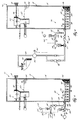
- Fig. 1 is a partially schematic side elevational view, partially in section, of a fluid treatment apparatus including a backflow prevention system embodying the invention.
- Fig. 2 is a view similar to Fig. 1 and shows a portion of an alternative fluid treatment apparatus including a backflow prevention system in accordance with a second embodiment of the invention.
- Fig. 3 is a view similar to Fig. 1 and shows a another alternative fluid treatment apparatus including a backflow prevention system in accordance with a third embodiment of the invention.
- a fluid treatment apparatus 10 which embodies the invention and which includes a filter bed or media bed reactor apparatus. While the reactor apparatus can be configured and operated in various ways (such as in fixed or fluid bed modes for example) as determined appropriate for the particular fluid to be treated and the particular processing objectives, in the embodiment illustrated in Fig. 1 the reactor apparatus is a fluid bed reactor 12.
- the fluid bed reactor 12 includes a columnar reactor tank 14 having an inlet 16 adjacent its base and an outlet 18 adjacent its top.
- the reactor tank 14 contains a media bed 20 comprised of particulate solids 22.
- the media bed 20 is fluidized as indicated by reference numeral 24.
- the media bed 20 settles to the bottom of the reactor tank 14 as indicated by reference numeral 26.
- the fluid bed reactor 12 can be employed in numerous applications to perform various different processes on different flowable materials including, for example, various liquids, gases and liquid/solid suspensions.
- the fluid treatment apparatus 10 is used in a waste water treatment facility to process waste water, and the fluid bed reactor 12 is operable biologically to remove impurities from the waste water passed therethrough.
- the particulate material making up the media bed 20 is preferably granular activated carbon or sand and biomass is carried on the particulate solids.
- the biomass consumes impurities in the waste water passed through the media bed 20 to produce a treated effluent (i.e., treated waste water) that forms an effluent head 28 above the media bed 20.
- a treated effluent i.e., treated waste water
- the treated effluent is then withdrawn from the reactor tank 14 through the outlet 18 which in the illustrated arrangement controls the level of the effluent head 28.
- One of the byproducts of the biological treatment process is biological growth within the media bed 20 which causes the media bed 20 to expand.
- the fluid bed reactor 12 is provided with a bed growth control apparatus 30.
- the structure and operation of the bed growth control apparatus 30 is fully explained in U.S. Patent Application Serial No. 195,397, filed February 14, 1994, and titled BIOMASS GROWTH CONTROL APPARATUS FOR FLUID BED BIOLOGICAL REACTOR, which is herein incorporated by reference.
- the bed growth control apparatus 30 will not be further discussed.
- Other suitable bed growth control apparatus are disclosed in U.S. Patent Nos. 4,250,033 and 4,177,144.
- the fluid treatment apparatus 10 is provided with a main fluid supply system 32
- the main fluid supply system 32 includes a fluid supply conduit or main line 34 and a pump 36 or other suitable means for pumping a main fluid 38 (i.e., untreated waste water) from a remote source (not shown) to the fluid bed reactor 12.
- a main fluid 38 i.e., untreated waste water
- the fluid bed reactor 12 To receive influent (including main fluid 38) and to introduce that influent into the reactor tank 14, the fluid bed reactor 12 includes a flow distribution system 40.
- the flow distribution system 40 includes a flow distributor 42 positioned adjacent the base of the reactor tank 14.
- the flow distributor 42 includes a tubular header member 44 that extends through the inlet 16 of the reactor tank 14 and that is connected to the main line 34.
- the header member 44 is manifolded to a plurality of downcomer pipes 46 that are connected to laterally extending pipes 48.
- the lateral pipes 48 are studded with downwardly extending nozzles 50 for delivering the influent into the reactor tank 14.
- the array of nozzles 50 is preferably spread over the bottom of the reactor tank 14 so that the influent is evenly distributed over the cross-sectional area of the reactor tank 14 to achieve a substantially uniform upflow therein.
- the flow distribution system 40 is provided with a backflow prevention system 54 for preventing the media bed 24 from backing up into the flow distributor 34 following interruption of the flow of main fluid 38.
- the backflow prevention system 54 is operable to flush the flow distributor 42 following a shut-down of the liquid treatment apparatus 10.
- the backflow prevention system 54 includes means for supplying an auxiliary fluid 56 to the flow distributor 42 to maintain some influent flow through (or back pressure in) the flow distributor 42.
- the means for supplying the auxiliary fluid 56 to the flow distributor 42 includes an auxiliary fluid supply conduit or auxiliary line 58 provided with a one-way check valve 60 and a manually operable valve 62.
- the auxiliary line 58 is connected between the main line 34 and an auxiliary fluid source 64 which in the illustrated arrangement is a municipal water supply.
- the backflow prevention system 54 is provided with actuating means for controlling the flow of auxiliary fluid 56 to the flow distributor 42.
- the actuating means is operable to initiate flow of auxiliary fluid 56 to the flow distributor 42 in response to the loss of power to the liquid treatment system 10 and includes a shutdown interlock assembly 66.
- the shutdown interlock assembly 66 includes a solenoid actuated fail-open valve 68 in the auxiliary line 58 and a solenoid actuated fail-close valve 70 in the main line 34.
- the fail-open valve 68 and the fail-close valve 70 are electrically interlocked and operate in response to a signal generated by an interlock (ISA standard) or a power loss indicator 72 that detects power loss to a motor (not shown) used to drive the pump 36.
- valve 62 Under normal operating conditions valve 62 is open, the fail-open valve 68 is closed, the fail-close valve 70 is open, and the pump 36 is powered to provide main fluid 38 to the reactor tank 14.
- the flow rate of the main fluid 38 supplied to the reactor tank 14 is controlled to insure an upflow velocity within the reactor tank 22 sufficient to maintain the media bed 20 in its fluidized state 24.
- the flow of main fluid 38 to the flow distributor 42 will diminish and the media bed 20 will begin to defluidize.
- the power loss also activates the indicator 72 of the shutdown interlock assembly 66 to automatically close the fail-close valve 70 and open the fail-open valve 68 to initiate the flow of auxiliary fluid 56 from the municipal water supply 64.
- the auxiliary fluid 56 flushes the flow distributor 42 to prevent media bed constituents from backing up into the nozzles 50. Unless power to the pump 36 is sooner restored, it is preferred that flushing with the auxiliary fluid 56 continue until the media bed 20 fully settles to its quiescent state 26. If desired, the auxiliary line 58 can then be closed via valve 62, and the fail-open and fail-close valves 68 and 70 reset to prepare the shutdown interlock assembly 66 for when the pump 36 is placed back in service.
- fluid treatment apparatus 74 that employs an alternative flow distribution system 76 that includes flow distributer 42 and a backflow prevention system 78 in accordance with a second, embodiment of the invention. Otherwise, fluid treatment apparatus 74 is similar to fluid treatment apparatus 10 (Fig. 1) and the same reference numerals are used to denote elements common to both.
- the means for supplying auxiliary fluid 56 to the flow distributor 42 includes an auxiliary line 80 provided with an anti-backflow pump 82 having its own uninterrupted power source, such as a DC battery 84.
- the auxiliary line 80 is also provided with a one-way check valve 86, a manually operable valve 88, and a rotometer 90 of suitable design to measure the flow rate, if any, through the auxiliary line 80.
- the auxiliary line 80 is connected between the main line 34 and a liquid storage tank 92 which acts as an auxiliary fluid source.
- the backflow prevention apparatus 74 also includes a modified shutdown interlock assembly 94.
- the shutdown interlock assembly 94 includes the fail-open and fail close valves 68 and 70 discussed above with respect to shutdown interlock assembly 66, and is also operable to interconnect the anti-backflow pump 82 and the DC battery 84 to activate the pump 82.
- main fluid 38 i.e., waste water
- main fluid 38 is pumped to the flow distributor 42 for introduction into the reactor tank 14 where it is treated as it ascends upwardly through the media bed 20.
- the shutdown interlock assembly 94 signals the fail-open valve 68 to open the auxiliary line 80 and the fail-close valve 70 to close the main line 34.
- the shutdown interlock assembly 94 also activates operation of the anti-backflow pump 82 to pump auxiliary fluid 56 from the storage tank 92 to the flow distributor 42.
- the auxiliary fluid 56 flushes the flow distributor 42 as the media bed 20 settles to prevent media bed constituents from backing up into the flow distributor 42.
- backflow prevention system 54 (Fig. 1) has a simpler construction than backflow prevention system 78 (Fig. 2)
- backflow prevention system 78 has the advantage of being usable where a municipal water supply or other ready supply of auxiliary fluid 56 is unavailable.
- FIG. 3 Illustrated in Fig. 3 is a fluid treatment apparatus 96 that employs a second alternative flow distribution system 98.
- the flow distribution system 98 includes flow distributer 42 and a backflow prevention system 100 in accordance with a third embodiment of the invention.
- Fluid treatment apparatus 96 is otherwise similar to fluid treatment apparatus 10 and 74 of Figs. 1 and 2, respectively, and like reference numerals denote elements common to all.
- the means for supplying auxiliary fluid 56 to the flow distributor 42 includes an auxiliary fluid source which in the illustrated arrangement is storage tank 102.
- the storage tank 102 is preferably an ASME (Section VIII code) pressure vessel rated at 100 psig and having a capacity to hold in excess of 1000 gallons of auxiliary fluid 56. If desired, the storage tank 102 can be internally coated so that potentially corrosive auxiliary fluids, such as sea water for example, can be used.
- the storage tank 102 is provided with a level gauge 104 including a site tube 106 and an associated valve arrangement including a vent valve 108.
- auxiliary line 110 is provided to provide communication between the storage tank 102 and the flow distributor 42.
- One end of the auxiliary line 110 is connected directly to the header member 44 which has been modified for that purpose.
- the auxiliary line 110 could be connected to the main line 34 (as indicated in broken lines in Fig. 3).
- the opposite end of the auxiliary line 110 is connected to the storage tank 102 and includes an extension 112 that extends downwardly into the storage tank 102.
- the auxiliary line 110 is also provided with a one-way check valve 114, a constriction orifice 116, and a pair of manually operable valves 118 and 120.
- Means are provided for charging the storage tank 102 with auxiliary fluid 56.
- the means for charging the storage tank 102 includes a fluid supply line 122 connected between a remote fluid source (not shown) and the auxiliary line 110.
- a one-way check valve 124 and a manually operable tank fill valve 126 are provided to control fluid flow to the storage tank 102.
- the backflow prevention apparatus 100 also includes alternative means for pumping or delivering the auxiliary fluid 56 from the storage tank 102 to the flow distributer 42 to replace the anti-backflow pump 82 and battery 84 used in the embodiment of Fig. 2.
- the alternative pumping means includes a pressurized air source 128 and an air line 130 connected between the air source 128 and the storage tank 102.
- the air line 130 is provided with a pressure regulator 132, a one-way check valve 134, and a manually operable air valve 136.
- the air line 130 is also provided with a pressure gauge 138 and a pressure release mechanism 140.
- the backflow prevention apparatus 100 also includes a modified shutdown interlock assembly 142 for activating the backflow prevention apparatus 100.
- the shutdown interlock assembly 142 includes a hand switch 144 and associated display light 146 and a conventional arrangement 148 that acts as a pilot or control valve for the fail-open valve 68.
- the arrangement 148 communicates with a pressurized air source, such as air source 128, and is used to manipulate the position of the fail-open valve 68.
- the storage tank 102 Prior to start-up of fluid treatment apparatus 96 the storage tank 102 is empty, the fail-open valve 68 and valves 118 and 120 are open, and the tank fill valve 126, the vent valve 108, and the air valve 136 are all closed.
- the fail-open valve 68 is reset by placing the hand switch 144 in a closed position to activate the interlock reset arrangement 148 to close the fail-open valve 68.
- the vent valve 108 and the fill valve 126 are manually opened and the storage tank 102 is filled to a predetermined level.
- the vent valve 108 and the fill valve 126 are manually closed and the air valve 136 is manually opened to pressurize the storage tank 102 to the setting of the regulator 132 (about 60 psig).
- the air valve 136 is then manually closed and the hand switch 144 for the fail-open valve 68 is placed in an AUTO position. At this point the backflow prevention system 100 is in a state of readiness.
- the fluid bed reactor 12 With the backflow prevention system 100 ready the fluid bed reactor 12 is placed in service by turning the main pump 36 on to pump main fluid 38 to the flow distributor 42 for introduction into the reactor tank 14.
- the fail-closed valve 70 remains open as long as power is supplied to the main pump 36.
- the pressure gauge 138 and the level gauge 104 are periodically checked to confirm the readiness of the backflow prevention system 100.
- the shutdown interlock assembly 142 automatically causes the fail-close valve 70 to close the main line 34 and the fail-open valve 68 to open the auxiliary line 110.
- Auxiliary fluid 56 from the storage tank 102 under the influence of the pressure within the storage tank 102, then flushes the flow distributor 42 as the media bed defluidizes.
- the constriction orifice 116 limits the flow rate through the auxiliary line 110 and in the illustrated arrangement that flow rate is limited initially to about 30 gallons per minute. As the media bed 20 settles and the pressure within the storage tank 102 falls, the flow rate through the auxiliary line 110 tapers off to about 10 gallons per minute.
- the backflow prevention apparatus 100 (Fig. 3) is advantageous over backflow prevention apparatus 78 (Fig. 2) in that the former does not require the battery 84 (which may take several hours to recharge) or any other uninterrupted power source.
- the backflow prevention apparatus 100 also provides a higher confidence level since the pressure gauge 138 and level gauge 104 give regular readings to confirm that the system is ready.
Landscapes
- Chemical & Material Sciences (AREA)
- Organic Chemistry (AREA)
- Engineering & Computer Science (AREA)
- Life Sciences & Earth Sciences (AREA)
- Chemical Kinetics & Catalysis (AREA)
- Water Supply & Treatment (AREA)
- Hydrology & Water Resources (AREA)
- Environmental & Geological Engineering (AREA)
- Combustion & Propulsion (AREA)
- Biodiversity & Conservation Biology (AREA)
- Microbiology (AREA)
- Devices And Processes Conducted In The Presence Of Fluids And Solid Particles (AREA)
- Devices For Conveying Motion By Means Of Endless Flexible Members (AREA)
- Infusion, Injection, And Reservoir Apparatuses (AREA)
- Jet Pumps And Other Pumps (AREA)
- Check Valves (AREA)
- Fluidized-Bed Combustion And Resonant Combustion (AREA)
- Feeding, Discharge, Calcimining, Fusing, And Gas-Generation Devices (AREA)
- Pipeline Systems (AREA)
- Biological Treatment Of Waste Water (AREA)
- Physical Or Chemical Processes And Apparatus (AREA)
Applications Claiming Priority (2)
| Application Number | Priority Date | Filing Date | Title |
|---|---|---|---|
| US23642294A | 1994-04-29 | 1994-04-29 | |
| US236422 | 1994-04-29 |
Publications (3)
| Publication Number | Publication Date |
|---|---|
| EP0679432A2 true EP0679432A2 (fr) | 1995-11-02 |
| EP0679432A3 EP0679432A3 (fr) | 1996-04-17 |
| EP0679432B1 EP0679432B1 (fr) | 1999-05-19 |
Family
ID=22889435
Family Applications (1)
| Application Number | Title | Priority Date | Filing Date |
|---|---|---|---|
| EP95301560A Expired - Lifetime EP0679432B1 (fr) | 1994-04-29 | 1995-03-09 | Système pour empecher le refoulement dans un réacteur à lit solide |
Country Status (11)
| Country | Link |
|---|---|
| US (1) | US5766491A (fr) |
| EP (1) | EP0679432B1 (fr) |
| JP (1) | JPH0854100A (fr) |
| KR (1) | KR950031205A (fr) |
| AT (1) | ATE180182T1 (fr) |
| AU (1) | AU1365795A (fr) |
| BR (1) | BR9501812A (fr) |
| CA (1) | CA2144028A1 (fr) |
| DE (1) | DE69509700T2 (fr) |
| DK (1) | DK0679432T3 (fr) |
| TW (1) | TW262396B (fr) |
Cited By (1)
| Publication number | Priority date | Publication date | Assignee | Title |
|---|---|---|---|---|
| WO2005094979A1 (fr) * | 2004-04-02 | 2005-10-13 | Statoil Asa | Reacteur a colonne a bulle de boue |
Families Citing this family (10)
| Publication number | Priority date | Publication date | Assignee | Title |
|---|---|---|---|---|
| KR100818768B1 (ko) * | 2002-02-20 | 2008-04-01 | 주식회사 케이씨씨 | 유동층 장치의 분산판 |
| US7754159B2 (en) * | 2007-06-27 | 2010-07-13 | Envirogen Technologies, Inc. | System and method for limiting backflow in a biological fluidized bed reactor |
| JP4994265B2 (ja) * | 2008-02-25 | 2012-08-08 | シャープ株式会社 | 水処理装置および水処理方法 |
| CN103113452B (zh) * | 2011-11-07 | 2015-06-03 | 河北百灵威超精细材料有限公司 | 一种毛地黄皂苷的提取纯化工艺 |
| JP6196556B2 (ja) * | 2014-01-16 | 2017-09-13 | 水ing株式会社 | 上向流型反応器の運転方法及び水処理装置 |
| CN104478986A (zh) * | 2014-12-30 | 2015-04-01 | 北京百灵威科技有限公司 | 一种高纯度皂苷产品的纯化工艺 |
| US20160310772A1 (en) * | 2015-04-21 | 2016-10-27 | Kenneth Tabor | Collection and Recycling System for Contents of Sprinkler System |
| JP6553433B2 (ja) * | 2015-07-10 | 2019-07-31 | 水ing株式会社 | 分散装置及びこれを具備する上向流式反応装置とその運転方法 |
| US10899703B2 (en) | 2017-03-10 | 2021-01-26 | Veolia North American Regeneration Services, LLC | Radical initiators and chain extenders for converting methane gas into methane-sulfonic acid |
| CA3093412C (fr) * | 2018-03-10 | 2023-02-21 | Veolia North America Regeneration Services, Llc | Composes, procedes et equipement pour convertir du gaz methane en acide methanesulfonique |
Citations (4)
| Publication number | Priority date | Publication date | Assignee | Title |
|---|---|---|---|---|
| EP0090450A1 (fr) * | 1982-03-29 | 1983-10-05 | Gist-Brocades N.V. | Réacteur à lit fluidisé pour la purification d'eau résiduaire |
| EP0145612A1 (fr) * | 1983-10-17 | 1985-06-19 | Austgen-Biojet International Pty. Limited | Réacteur à lit fluidisé |
| FR2588772A1 (fr) * | 1985-10-21 | 1987-04-24 | Charbonnages De France | Dispositif pour l'alimentation des ouvertures d'une grille de fluidisation en gaz de decolmatage |
| DE3712166A1 (de) * | 1986-04-10 | 1987-10-15 | Ahlstroem Oy | Verfahren und vorrichtung zur verteilung von fluidisierungsgas in einem wirbelschichtreaktor |
Family Cites Families (11)
| Publication number | Priority date | Publication date | Assignee | Title |
|---|---|---|---|---|
| US3879287A (en) * | 1972-10-31 | 1975-04-22 | Robert R Porter | Continuous ion exchange process and apparatus |
| US3956128A (en) * | 1973-07-16 | 1976-05-11 | Degremont, S.A. | Apparatus for treating industrial and domestic waste waters |
| US4094790A (en) * | 1976-11-11 | 1978-06-13 | Industrial Filter & Pump Mfg. Co. | Distributor collector assembly |
| US4098695A (en) * | 1977-04-27 | 1978-07-04 | Industrial Filter & Pump Mfg. Co. | Distributor-collector assembly |
| US4202774A (en) * | 1978-05-24 | 1980-05-13 | Dorr-Oliver Incorporated | Flow distributor for fluid bed biological reactor |
| US4170626A (en) * | 1978-07-06 | 1979-10-09 | Uop Inc. | Gas distribution apparatus for use with fluidized beds |
| US4322299A (en) * | 1980-08-18 | 1982-03-30 | General Filter Company | Method of simultaneous air-water wash of multiple-media filters |
| CH655294A5 (de) * | 1981-05-20 | 1986-04-15 | Sulzer Ag | Verfahren zur denitrifikation von wasser und anlage zur durchfuehrung des verfahrens. |
| US4412003A (en) * | 1981-07-30 | 1983-10-25 | Dorr-Oliver Inc. | Integral flow circulator for fluid bed reactor |
| US4464262A (en) * | 1982-07-01 | 1984-08-07 | Ecolotrol, Inc. | Liquid flow distributor |
| US5068034A (en) * | 1990-05-03 | 1991-11-26 | Unilift Corporation | Purification underdrain with means to compensate for flow and pressure differences between laterals |
-
1995
- 1995-03-06 CA CA 2144028 patent/CA2144028A1/fr not_active Abandoned
- 1995-03-07 AU AU13657/95A patent/AU1365795A/en not_active Abandoned
- 1995-03-09 AT AT95301560T patent/ATE180182T1/de active
- 1995-03-09 EP EP95301560A patent/EP0679432B1/fr not_active Expired - Lifetime
- 1995-03-09 DE DE1995609700 patent/DE69509700T2/de not_active Expired - Fee Related
- 1995-03-09 DK DK95301560T patent/DK0679432T3/da active
- 1995-03-20 KR KR1019950005741A patent/KR950031205A/ko not_active Application Discontinuation
- 1995-04-10 TW TW84103442A patent/TW262396B/zh active
- 1995-04-27 BR BR9501812A patent/BR9501812A/pt not_active Application Discontinuation
- 1995-04-28 JP JP14105695A patent/JPH0854100A/ja not_active Withdrawn
-
1996
- 1996-06-03 US US08/656,705 patent/US5766491A/en not_active Expired - Lifetime
Patent Citations (4)
| Publication number | Priority date | Publication date | Assignee | Title |
|---|---|---|---|---|
| EP0090450A1 (fr) * | 1982-03-29 | 1983-10-05 | Gist-Brocades N.V. | Réacteur à lit fluidisé pour la purification d'eau résiduaire |
| EP0145612A1 (fr) * | 1983-10-17 | 1985-06-19 | Austgen-Biojet International Pty. Limited | Réacteur à lit fluidisé |
| FR2588772A1 (fr) * | 1985-10-21 | 1987-04-24 | Charbonnages De France | Dispositif pour l'alimentation des ouvertures d'une grille de fluidisation en gaz de decolmatage |
| DE3712166A1 (de) * | 1986-04-10 | 1987-10-15 | Ahlstroem Oy | Verfahren und vorrichtung zur verteilung von fluidisierungsgas in einem wirbelschichtreaktor |
Cited By (1)
| Publication number | Priority date | Publication date | Assignee | Title |
|---|---|---|---|---|
| WO2005094979A1 (fr) * | 2004-04-02 | 2005-10-13 | Statoil Asa | Reacteur a colonne a bulle de boue |
Also Published As
| Publication number | Publication date |
|---|---|
| JPH0854100A (ja) | 1996-02-27 |
| AU1365795A (en) | 1995-11-09 |
| BR9501812A (pt) | 1996-02-27 |
| EP0679432A3 (fr) | 1996-04-17 |
| EP0679432B1 (fr) | 1999-05-19 |
| CA2144028A1 (fr) | 1995-10-30 |
| ATE180182T1 (de) | 1999-06-15 |
| DE69509700D1 (de) | 1999-06-24 |
| TW262396B (fr) | 1995-11-11 |
| DK0679432T3 (da) | 1999-11-08 |
| US5766491A (en) | 1998-06-16 |
| KR950031205A (ko) | 1995-12-18 |
| DE69509700T2 (de) | 2000-03-02 |
Similar Documents
| Publication | Publication Date | Title |
|---|---|---|
| EP0679432B1 (fr) | Système pour empecher le refoulement dans un réacteur à lit solide | |
| US6431950B1 (en) | Point-of-use fluid regulating system for use in the chemical-mechanical planarization of semiconductor wafers | |
| US3920550A (en) | Process and equipment for automatic chemical-biological wastewater treatment with provisions for recycle and reuse | |
| EP1192000B1 (fr) | Appareil et procedes permettant de regenerer des matieres particulaires | |
| US4931183A (en) | Process and apparatus for the biological purification of water | |
| US7699977B2 (en) | Assembling unit for filtration and adsorption of waste and sewage water | |
| EP0428054A1 (fr) | Dispositif pour introduire un mélange de catalyseurs en forme de boue dans un réacteur de polymérisation | |
| EP1375414A2 (fr) | Dispositif et procédé de distribution de produits chimiques | |
| WO1988009740A1 (fr) | Installation de traitement des eaux d'egout | |
| AU1885302A (en) | Apparatus for sewage treatment | |
| WO1996027558A1 (fr) | Procede et appareil de reaction de matiere oxydable avec des particules | |
| WO2012138702A1 (fr) | Système précis de manipulation de matériau en vrac sec précis et son procédé d'utilisation | |
| US4317732A (en) | Liquid reconditioning system | |
| EP0774134B1 (fr) | Systeme et procede de reduction de pression | |
| EP0885174A1 (fr) | Denitrification biologique de l'eau | |
| US5441642A (en) | Method and apparatus for controlled biological treatment of waste water | |
| US6521126B2 (en) | Pipe gallery for water filtration systems | |
| US4966693A (en) | Apparatus for processing coolant | |
| JP3836576B2 (ja) | 流動床式排水処理装置 | |
| CA2681086A1 (fr) | Appareil de traitement des eaux usees | |
| US6953068B2 (en) | Acetylene distribution system | |
| Rebis | A guideline to operational procedures and design for granular carbon systems wastewater applications | |
| JP2023136258A (ja) | 水処理装置 | |
| KR20110057690A (ko) | 선박용 식수공급장치 | |
| JPH0316161B2 (fr) |
Legal Events
| Date | Code | Title | Description |
|---|---|---|---|
| PUAI | Public reference made under article 153(3) epc to a published international application that has entered the european phase |
Free format text: ORIGINAL CODE: 0009012 |
|
| AK | Designated contracting states |
Kind code of ref document: A2 Designated state(s): AT BE CH DE DK ES FR GB IE IT LI LU NL PT SE |
|
| PUAL | Search report despatched |
Free format text: ORIGINAL CODE: 0009013 |
|
| AK | Designated contracting states |
Kind code of ref document: A3 Designated state(s): AT BE CH DE DK ES FR GB IE IT LI LU NL PT SE |
|
| 17P | Request for examination filed |
Effective date: 19960625 |
|
| 17Q | First examination report despatched |
Effective date: 19970429 |
|
| GRAG | Despatch of communication of intention to grant |
Free format text: ORIGINAL CODE: EPIDOS AGRA |
|
| RAP1 | Party data changed (applicant data changed or rights of an application transferred) |
Owner name: UNITED STATES FILTER CORPORATION |
|
| GRAG | Despatch of communication of intention to grant |
Free format text: ORIGINAL CODE: EPIDOS AGRA |
|
| GRAH | Despatch of communication of intention to grant a patent |
Free format text: ORIGINAL CODE: EPIDOS IGRA |
|
| GRAH | Despatch of communication of intention to grant a patent |
Free format text: ORIGINAL CODE: EPIDOS IGRA |
|
| GRAA | (expected) grant |
Free format text: ORIGINAL CODE: 0009210 |
|
| AK | Designated contracting states |
Kind code of ref document: B1 Designated state(s): AT BE CH DE DK ES FR GB IE IT LI LU NL PT SE |
|
| PG25 | Lapsed in a contracting state [announced via postgrant information from national office to epo] |
Ref country code: NL Free format text: LAPSE BECAUSE OF FAILURE TO SUBMIT A TRANSLATION OF THE DESCRIPTION OR TO PAY THE FEE WITHIN THE PRESCRIBED TIME-LIMIT Effective date: 19990519 Ref country code: LI Free format text: LAPSE BECAUSE OF FAILURE TO SUBMIT A TRANSLATION OF THE DESCRIPTION OR TO PAY THE FEE WITHIN THE PRESCRIBED TIME-LIMIT Effective date: 19990519 Ref country code: IT Free format text: LAPSE BECAUSE OF FAILURE TO SUBMIT A TRANSLATION OF THE DESCRIPTION OR TO PAY THE FEE WITHIN THE PRE;WARNING: LAPSES OF ITALIAN PATENTS WITH EFFECTIVE DATE BEFORE 2007 MAY HAVE OCCURRED AT ANY TIME BEFORE 2007. THE CORRECT EFFECTIVE DATE MAY BE DIFFERENT FROM THE ONE RECORDED.SCRIBED TIME-LIMIT Effective date: 19990519 Ref country code: FR Free format text: LAPSE BECAUSE OF FAILURE TO SUBMIT A TRANSLATION OF THE DESCRIPTION OR TO PAY THE FEE WITHIN THE PRESCRIBED TIME-LIMIT Effective date: 19990519 Ref country code: ES Free format text: THE PATENT HAS BEEN ANNULLED BY A DECISION OF A NATIONAL AUTHORITY Effective date: 19990519 Ref country code: CH Free format text: LAPSE BECAUSE OF FAILURE TO SUBMIT A TRANSLATION OF THE DESCRIPTION OR TO PAY THE FEE WITHIN THE PRESCRIBED TIME-LIMIT Effective date: 19990519 Ref country code: BE Free format text: LAPSE BECAUSE OF FAILURE TO SUBMIT A TRANSLATION OF THE DESCRIPTION OR TO PAY THE FEE WITHIN THE PRESCRIBED TIME-LIMIT Effective date: 19990519 Ref country code: AT Free format text: LAPSE BECAUSE OF FAILURE TO SUBMIT A TRANSLATION OF THE DESCRIPTION OR TO PAY THE FEE WITHIN THE PRESCRIBED TIME-LIMIT Effective date: 19990519 |
|
| REF | Corresponds to: |
Ref document number: 180182 Country of ref document: AT Date of ref document: 19990615 Kind code of ref document: T |
|
| REG | Reference to a national code |
Ref country code: CH Ref legal event code: EP |
|
| REG | Reference to a national code |
Ref country code: IE Ref legal event code: FG4D |
|
| REF | Corresponds to: |
Ref document number: 69509700 Country of ref document: DE Date of ref document: 19990624 |
|
| PG25 | Lapsed in a contracting state [announced via postgrant information from national office to epo] |
Ref country code: PT Free format text: LAPSE BECAUSE OF FAILURE TO SUBMIT A TRANSLATION OF THE DESCRIPTION OR TO PAY THE FEE WITHIN THE PRESCRIBED TIME-LIMIT Effective date: 19990819 |
|
| EN | Fr: translation not filed | ||
| REG | Reference to a national code |
Ref country code: DK Ref legal event code: T3 |
|
| REG | Reference to a national code |
Ref country code: CH Ref legal event code: PL |
|
| PGFP | Annual fee paid to national office [announced via postgrant information from national office to epo] |
Ref country code: DE Payment date: 19991229 Year of fee payment: 6 |
|
| PGFP | Annual fee paid to national office [announced via postgrant information from national office to epo] |
Ref country code: DK Payment date: 20000121 Year of fee payment: 6 |
|
| PG25 | Lapsed in a contracting state [announced via postgrant information from national office to epo] |
Ref country code: LU Free format text: LAPSE BECAUSE OF NON-PAYMENT OF DUE FEES Effective date: 20000309 Ref country code: GB Free format text: LAPSE BECAUSE OF NON-PAYMENT OF DUE FEES Effective date: 20000309 |
|
| PLBE | No opposition filed within time limit |
Free format text: ORIGINAL CODE: 0009261 |
|
| STAA | Information on the status of an ep patent application or granted ep patent |
Free format text: STATUS: NO OPPOSITION FILED WITHIN TIME LIMIT |
|
| 26N | No opposition filed | ||
| PGFP | Annual fee paid to national office [announced via postgrant information from national office to epo] |
Ref country code: IE Payment date: 20000904 Year of fee payment: 6 |
|
| GBPC | Gb: european patent ceased through non-payment of renewal fee |
Effective date: 20000309 |
|
| PG25 | Lapsed in a contracting state [announced via postgrant information from national office to epo] |
Ref country code: IE Free format text: LAPSE BECAUSE OF NON-PAYMENT OF DUE FEES Effective date: 20010309 Ref country code: DK Free format text: LAPSE BECAUSE OF NON-PAYMENT OF DUE FEES Effective date: 20010309 |
|
| REG | Reference to a national code |
Ref country code: DK Ref legal event code: EBP |
|
| PG25 | Lapsed in a contracting state [announced via postgrant information from national office to epo] |
Ref country code: DE Free format text: LAPSE BECAUSE OF NON-PAYMENT OF DUE FEES Effective date: 20020101 |
|
| REG | Reference to a national code |
Ref country code: IE Ref legal event code: MM4A |
|
| PGFP | Annual fee paid to national office [announced via postgrant information from national office to epo] |
Ref country code: SE Payment date: 20130311 Year of fee payment: 19 |
|
| REG | Reference to a national code |
Ref country code: SE Ref legal event code: EUG |
|
| PG25 | Lapsed in a contracting state [announced via postgrant information from national office to epo] |
Ref country code: SE Free format text: LAPSE BECAUSE OF NON-PAYMENT OF DUE FEES Effective date: 20140310 |