EP0679263B1 - Radar system - Google Patents
Radar system Download PDFInfo
- Publication number
- EP0679263B1 EP0679263B1 EP94902135A EP94902135A EP0679263B1 EP 0679263 B1 EP0679263 B1 EP 0679263B1 EP 94902135 A EP94902135 A EP 94902135A EP 94902135 A EP94902135 A EP 94902135A EP 0679263 B1 EP0679263 B1 EP 0679263B1
- Authority
- EP
- European Patent Office
- Prior art keywords
- radar
- transmitter
- transmitters
- unit
- receiver
- Prior art date
- Legal status (The legal status is an assumption and is not a legal conclusion. Google has not performed a legal analysis and makes no representation as to the accuracy of the status listed.)
- Expired - Lifetime
Links
- 230000001419 dependent effect Effects 0.000 claims description 5
- 238000000034 method Methods 0.000 claims description 2
- 125000004122 cyclic group Chemical group 0.000 claims 1
- 230000001960 triggered effect Effects 0.000 abstract 1
- 238000010586 diagram Methods 0.000 description 15
- 230000000694 effects Effects 0.000 description 15
- 230000008901 benefit Effects 0.000 description 8
- 238000010276 construction Methods 0.000 description 8
- 230000008878 coupling Effects 0.000 description 5
- 238000010168 coupling process Methods 0.000 description 5
- 238000005859 coupling reaction Methods 0.000 description 5
- 238000002592 echocardiography Methods 0.000 description 4
- 230000006872 improvement Effects 0.000 description 4
- 238000001208 nuclear magnetic resonance pulse sequence Methods 0.000 description 4
- 229920006395 saturated elastomer Polymers 0.000 description 3
- 238000002834 transmittance Methods 0.000 description 3
- 230000003111 delayed effect Effects 0.000 description 2
- 238000005516 engineering process Methods 0.000 description 2
- 230000009467 reduction Effects 0.000 description 2
- 230000000717 retained effect Effects 0.000 description 2
- 238000004458 analytical method Methods 0.000 description 1
- 230000008859 change Effects 0.000 description 1
- 230000000052 comparative effect Effects 0.000 description 1
- 230000003247 decreasing effect Effects 0.000 description 1
- 238000001514 detection method Methods 0.000 description 1
- 238000010304 firing Methods 0.000 description 1
- 230000008520 organization Effects 0.000 description 1
- 230000008092 positive effect Effects 0.000 description 1
- 230000003252 repetitive effect Effects 0.000 description 1
- 230000035945 sensitivity Effects 0.000 description 1
- 238000000926 separation method Methods 0.000 description 1
- 230000007480 spreading Effects 0.000 description 1
- 230000001360 synchronised effect Effects 0.000 description 1
- 239000003643 water by type Substances 0.000 description 1
Images




Classifications
-
- G—PHYSICS
- G01—MEASURING; TESTING
- G01S—RADIO DIRECTION-FINDING; RADIO NAVIGATION; DETERMINING DISTANCE OR VELOCITY BY USE OF RADIO WAVES; LOCATING OR PRESENCE-DETECTING BY USE OF THE REFLECTION OR RERADIATION OF RADIO WAVES; ANALOGOUS ARRANGEMENTS USING OTHER WAVES
- G01S13/00—Systems using the reflection or reradiation of radio waves, e.g. radar systems; Analogous systems using reflection or reradiation of waves whose nature or wavelength is irrelevant or unspecified
- G01S13/02—Systems using reflection of radio waves, e.g. primary radar systems; Analogous systems
- G01S13/06—Systems determining position data of a target
- G01S13/08—Systems for measuring distance only
- G01S13/10—Systems for measuring distance only using transmission of interrupted, pulse modulated waves
- G01S13/24—Systems for measuring distance only using transmission of interrupted, pulse modulated waves using frequency agility of carrier wave
-
- G—PHYSICS
- G01—MEASURING; TESTING
- G01S—RADIO DIRECTION-FINDING; RADIO NAVIGATION; DETERMINING DISTANCE OR VELOCITY BY USE OF RADIO WAVES; LOCATING OR PRESENCE-DETECTING BY USE OF THE REFLECTION OR RERADIATION OF RADIO WAVES; ANALOGOUS ARRANGEMENTS USING OTHER WAVES
- G01S13/00—Systems using the reflection or reradiation of radio waves, e.g. radar systems; Analogous systems using reflection or reradiation of waves whose nature or wavelength is irrelevant or unspecified
- G01S13/87—Combinations of radar systems, e.g. primary radar and secondary radar
-
- G—PHYSICS
- G01—MEASURING; TESTING
- G01S—RADIO DIRECTION-FINDING; RADIO NAVIGATION; DETERMINING DISTANCE OR VELOCITY BY USE OF RADIO WAVES; LOCATING OR PRESENCE-DETECTING BY USE OF THE REFLECTION OR RERADIATION OF RADIO WAVES; ANALOGOUS ARRANGEMENTS USING OTHER WAVES
- G01S7/00—Details of systems according to groups G01S13/00, G01S15/00, G01S17/00
- G01S7/02—Details of systems according to groups G01S13/00, G01S15/00, G01S17/00 of systems according to group G01S13/00
- G01S7/28—Details of pulse systems
- G01S7/282—Transmitters
Definitions
- the present invention relates to a device of a radar system as indicated in the introduction to claim 1.
- the invention relates to an improvement of the radar systems as they are known today.
- the navigational radar of today has not changed essentially for many years. Taking into account that the clarity of the picture has the greatest significance in bad weather, one might be tempted to say that the majority of radar sets are of relatively poorer quality than they were earlier.
- PRF pulse repetition frequency
- US patent No. 4.197.540 deals with a CW-radar. This proposed radar system could however, not be realized because of the current klystron which could only transmit with limited effect.
- a klystron of the type 2-K25 was used.
- Several klystrons are used in one and the same radar set, and every transmitter includes its own specific receiver. If one looks at the truth table of US-patent certificate 4.197.540 one will find that RX1 will always be closed in the transmitting time of TX1, RX2 will always be closed in the transmitting time of TX2 and so forth.
- RX1 and RX2 are open, when TX3 transmits, RX2 and RX3 are open when TX1 transmits.
- TX3 transmits RX2 and RX3 are open when TX1 transmits.
- the consequence of this is that if there are, three TRX's, each of the transmitters TX will transmit 1/3 of a sequence distance. If 6 NM are displayed, for example, the individual TX will transmit the equivalent in time to 2 NM. This means that the RX's will always be turned off sequentially in 1/3 of a transmitting sequence, that is to say in 2NM in accordance with the example.
- the purpose of the invention is to obtain a new and considerably improved radar compared with those which are known today.
- each transmitter and the appurtenant receiver forms an independent radar set as part of a system whereby the radar set, without being dependent on the other transmitters and receivers, produces radar signals and receives radar signals.
- the radar system of the invention is particularly suitable for the navigation of vessels.
- each individual transmitter transmits with different frequency.
- the frequency distance are separated and must equal the minimum bandwidth of the individual receiver, in practice, this is achieved by adding 5 MHZ to maintain good channel separation.
- repeated echoes have always been an enemy to all pulsating radar sets.
- the present solution of spreading the frequency for both transmitter and receiver one can indirectly use repetitive echoes, this relating to the sum of PRF. This means that even if one uses extremely high PRF, one will be able to present a radar picture which "looks" further than the PRF alone could imply.
- the pulse length is chosen in relation to the choice of PRF and the aerial's rotation speed. If one transmits with an extremely high PRF it is also advantageous to be able to proportionally reduce the pulse length. This reduction of the pulse length which preferably is effected, gives two possibilities. Firstly, if the relative transmitting effect is retained, the life expectancy of the magnetron will increase correspondingly. The second possibility, if the pulse length is reduced, the effect can increase correspondingly without the life expectancy of the magnetron becoming shorter.
- the enclosed fig. 1 shows a diagram of the sequences between the transmitters (TX1-TX2-TX3) and the receivers (RX1-RX2-RX3) according to the previously mentioned US patent No 4.197.540, of which the radar set is constructed.
- the diagram will not be referred to further, as it is previously mentioned in this description. It will, however, be referred to in conjunction with a comparison between the corresponding sequence diagram for the radar set according to the present invention.
- the radar system includes a trigger-unit 10, a modulator, and transmitter unit 12, an aerial-unit (wave guide and scanner unit) 14, a receiver unit 16 and a signal processing unit, preferably of the type ARPA/REX which will be explained later.
- the explanation of the trigger unit 10 shown in fig. 3, is based on a specific example where 3 transmitters and 3 receivers are used, and where the pulse repetition frequency PRF is fixed from the aerial and set to 9000 hz (i.e. the PRF is 3000 from each transmitter).
- the trigger unit 10 includes a pre-trigger 20 and a main trigger 22.
- the exit TP1 from the pre-trigger 20 can, for example, oscillate with a pulse repetition frequency of 9000 hz as shown diagrammatically in the figure referring to TP1.
- the output from the pre-trigger 20 feeds the entrance to the main-trigger 22.
- the main-trigger 22 divides the pre-trigger signal to the three points A, B, and C. The distribution will take place in an established sequence.
- the pulse frequency from the pre-trigger 20 is divided by 3 and gives an out-going pulse frequency for each of the main-trigger outputs 22A, 22B, 22C of 3000 hz, when the PRF equals 9000 hz. Reference is made to the diagram in fig. 8.
- the explanation of the transmitter-unit 14 which is shown in fig.4 is based on the use of the three transmitters TX1, TX2, TX3 as shown in fig. 3.
- the transmitter unit 14 comprises three modulators 24, 26, 28 and three transmitters TX1,TX2,TX3. Each of the three modulators 24, 26, and 28 is connected to an individual transmitter TX1,TX2,TX3.
- the exits E,F,G from the transmitters are connected to a common aerial through the respective circulators S1, S2, and S3.
- the out-going frequencies from the transmitters differ in relation to each other.
- the pulse repetition frequency PRF and the sequence to the aerial correspond with the exit signal A,B,C produced by the trigger-unit.
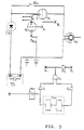
- fig. 5 shows a specific embodiment of the pulse-shaper unit of the transmitter-part in the radar system of the invention.
- the coupling of fig. 5 represents each of the transmitter parts TX1-TX3 in fig. 4.
- the entrance represents a pulse-transformer T1, whilst the output comprises a transmitter magnetron V3.
- a diode D1 is coupled in series with the relay RL1.
- the cathode of diode D1 is coupled to the pulse-transformer T1.
- a guided diode V2 is coupled in parallel with the relay RL1 which may comprise a triode, a tetrode or a thyristor.
- This dirigible diode V2 has its anode facing the magnetron V3 whilst the cathode faces the anode of the diode D1.
- An additional guided diode V1 is coupled between the V2 diode's cathode and point 3 on the pulse-transformer T1, i.e. on the earth side of the magnetron (cathode) the V1 and V2 cathodes are coupled together.
- a relay RL2 is coupled to the anode of V1.
- DY includes a delay circuit.
- U1, U2, U3 and U4 are NAND-gates.
- MD1 consists of a multivib. and a variable delay gate, time set 5-40 ns.
- the guiding circuit is connected as follows: the output from the delay circuit DY branches off and leads to the entrance of NAND-gate U1 and entrance MD1, respectively (multivib./variable delay port).
- the output MD1 is carried forward to the entrance of NAND-gate U2.
- NAND-gates U1 and U2 are carried forward to their own separate entrance in NAND-gate U3.
- the output from U3 branches off to the connecting point Al and entrance NAND-gate U4, respectively.
- the exit from U4 is carried forward to the connecting point B1.
- the connection points Al and B1 are connected between the grids of the diodes V1 and V2 via the connecting points A and B as shown on the figure.
- the exit DY and MD1 is logically 1.
- the output U1 and U2 are logically 0.
- the output U3 is logically 1.
- the exit U4 is logically 0. That is to say that Al holds A positive and V1 in saturation, whilst V2 is cut off.
- MD1 has an inner delay 0-40 ns. and maintains MDl output in the delay time logically 1.
- the switch system outlined on top of figure 5 will function as follows, guided by the circuit at the bottom of the figure.
- the positive moving pulse entering into the pulse-transformer builds up point 4 negative.
- point 3 is linked to point 4.
- the tetrode V2 is at the same time cut off and keeps the magnetron shut out from the circuit.
- the point 4 of the pulse transformer has attained its maximum negative voltage V1 switches to cut off and simultaneously V2 becomes saturated.
- the negative-moving pulse that is now being led into the magnetron has extremely steep leading edges (the steepness is measured to less than 5 ns).
- the pulse length can be decreased by less time than previously mentioned, by using the same coupling of triodes, tetrodes or thyristors as shown in figure 5, but differ in that switches are substituted with primed-TR-cells.
- the switching itself must take place in the wave-guide. The switching then occurs between the aerial and a dummy-load.
- This solution may give pulse lengths of a duration of down to 4-5 ns. The gain would be of little use.
- This type of coupling is also expensive as it requires expensive solutions for the construction and composition of the wave-guide.
- the explanation of the aerial unit which is outlined in figure 6, is related to the example with three transmitters TX1,TX2,TX3 and the three respective receivers RX1, RX2, RX3.
- the signals E, F, G from the transmitters TX1, TX2, TX3 are fed to the scanner 30 through the circulators S1, S2, S3.
- the sequence and the PRF from the scanners are the same as the output from the transmitter unit.
- the TR-cells 32, 34 and 36 are closed (cut off) in unison with the PRF, in that the these signals are transmitted via their respective connections 38, 40 and 42. This means that all TR-cells are cut off simultaneously, i.e. in the time span as the transmitter transmits signals to the scanner 30.
- the aerial one can use either a parabolic aerial or a slotted wave guide.
- the parabolic aerial is better than the slotted wave guide.
- the very best alternative would be a totally parabolic aerial.
- a totally parabolic aerial can only transmit and receive in a limited vertical and horizontal area (pencil beam).
- pencil beam There is a considerable advantage in channelling most of the power in a thin circular beam. This means that a relatively low cloud covering with a relatively high rain content will not affect the functioning of the radar.
- Another benefit is that one can use all advantages with regard to polarisation technology as a means of a clutter function and to a certain extent, as a remedy against interference/jamming.
- this type of aerial would be very expensive as it must be gyro-stabilized at all levels. This solution is better suited for military purposes.
- the receiver unit 16 (see figure 7) is made up of three separate receivers RX1, RX2 RX3. As shown on figures 6-7 each receiver RX1,RX2,RX3 is connected to the common aerial through its respective circulator S1,S2,S3 and a TR-cell is connected between each circulator and receiver.
- the receivers RX1, RX2, RX3 are syntonized in frequencies corresponding to their respective transmitters. However the frequency dispersal, that is to say the distance between the receivers (on account of the frequencies given out by the transmitters) is so large that the receiver only "sees" radar signals from its own specific transmitter.
- each receiver feeds each individual radar-extractor (ARPA).
- ARPA radar-extractor
- the receivers are simultaneously coupled to a common extractor. This, so as to utilize the potential that lies in the added quantity of information inherent in this construction.
- the signal processing in the receiver part should start as soon as possible. This means that signal processing should start in or just after the TR-cell. This is, so as to avoid driving the receiver into saturation from echoes entering from relatively closely situated objects. Since the transmitter pulse has an extremely steep leading edge of the transmitting pulse itself, the TR-cells should be primed. This is also because, in this case, the switching in a TR-cell operates too slow, (we refer to the characteristics of a TR-cell).
- FIG. 8 shows the sequence diagram for the pulse sequence exit from the pre-trigger 20 and the main trigger (as in figure 3.).
- the top line in figure 8 shows TP1, i.e. the pattern for the total pulse transmittance from the transmitter unit 14, while the three bottom lines show the pulse transmittance from each of the individual transmitters A, B, and C.
- the index numbers 0, 1, 2ising, show the pulse number from each of the transmitters.
- the pulse transmittances are indicated with upward directed lines.
- Figure 9 shows the sequence diagram for the pulse sequence entrance of the pulses RX1 K., RX2 L. and RX3 M to the receiver unit.
- the top line of the figure shows TP1, i.e. the sequences for the delivered signals from the transmitter as shown in figure 4. (see also figure 8).
- the bottom three lines show the opening sequences as well as the closing (cut off) of the receivers for the reception of the pulses during the time period where the transmitters emit pulses considered in relation to TP1.
- the cut off is indicated by vertical lines.
- the diagram shows in greater detail that RX1 K (receiver RX1 K opens first in the consecutive order of the receivers. This opening takes place when RP1 produces the first pulse.
- the opening of the receiver RX1 occurs, therefore, at the same moment as the transmitter TX1 has emitted its transmitter pulse.
- the receiver RX1 closes (simultaneously TX2 starts transmitting).
- the transmitter TX2 has transmitted its transmitter pulse the receivers RX1 and RX2 open. This means that the receivers RX1 and RX2 receive radar signals simultaneously, but the radar signals which are supplied to the receiver, are displaced with respect to time corresponding to the elapsed time between the first and second pulses given by TP1 (1/9000 sec.)
- sequence pulse number 3 in TP1 arises, the receivers RX1 and RX2 close (simultaneously TX3 starts transmitting).
- the transmitter TX3 has transmitted its transmitter pulse all receivers open. This means that the receivers receive radar signals simultaneously, but the radar signals which are supplied to the receiver, are displaced with respect to time.
- the time between the second and third pulses given by TP1 (1/9000 sec) determines the time difference between the video signal arising in the receivers RX2 and RX3.
- the ARPA/ radar extractors should have the best conditions possible to be able to see optional objects in the field, which would be "blind” if the trigger pulses were completely synchronized in relation to each other.
- the multiple echoes are presented on a display, one or a plurality of areas will be without any information.
- the width of the field is, however, not greater than the transmitter pulse duration. In practice this means that one will have a circle without any information which constitutes the minimum of 1 ms.
- the explanation for this lies in the TR-cells relatively slack flank after the keep alive voltage and/or the transmitting pulse has ceased. This "blind" field can be avoided to a certain extent by wobbling the PRF between the individual transmitters.
- the off-centring can be brought about and used in a completely different way than earlier.
- the radar picture will have a multiplied density of information. For example, this permits off-centring out to 6NM, at the same time as the radar screen scale is set to 0.25 NM.
- two separate displays many possibilities and applications exist. One can for example, "zoom" into an area that requires closer attention, and at the same time as valuable information around ones own vessel, is available.
- ARPA radar extractor
- An ARPA/radar extractor is a computer in which video signals are processed digitally and which in this way may sample the signals, i.e. calculate course, speed, and angle speed. The conditions for the parameters may be changed both manually and automatically. This signal processing technology is well known.
- TRX units may be considered as individually independent radar units, and function as such, (confer with claim 2).
- the manner in which the system mutually work does not differ from other radar units where the same coupling is given in a comparable block diagram. This is conditional upon the current TRX being conveyed to the trigger.
- the feature which makes the coupling particularly special is the cooperation carried out by the individual TRXs. Said cooperation between the TRX's is distributed by the trigger. The sum total of information that derives from the RX's is the result of this cooperation.
- the example will give us a PRF of 9000 fixed from an aerial. Since the transmitters mutually do not work at the same frequency there is a corresponding frequency deviation of the receivers. The receivers are syntonized to their respective transmitters.
- the construction of a radar set has clear advantages over the more current radar set construction.
- the detection range of the radar set neither relies on, or is determined by the pulse repetition frequency PRF, it also indirectly solves other important parameters.
- the rotation speed of the aerial is partly PRF dependent. This means that by increasing the PRF, the relative rotation speed of the aerial may also be increased. This increase in PRF and rotation speed of the aerial will on a technical basis, increase the amount of video-information. This situation with increased PRF and increased aerial rotation gives two considerable advantages for an ARPA/REX.
- said radar construction may be adapted to comply with "The International Maritime Organization" (IMO) requesting vessels over a certain size having a minimum of two radar sets. This is achieved by using two parallel aerials where the switching between the aerials is effected mechanically in wave guide. This is more economical related to the request for two radar sets, and at the same time one may retain the technical improvements of the video information.
- IMO The International Maritime Organization
- the construction in itself opens up the possibility of increasing the amount of information to the display in threefold (depending upon the number of interconnected units).
- the TRX's may operate separately so as to satisfy requirements and request for two or more radar sets.
Landscapes
- Engineering & Computer Science (AREA)
- Radar, Positioning & Navigation (AREA)
- Remote Sensing (AREA)
- Computer Networks & Wireless Communication (AREA)
- Physics & Mathematics (AREA)
- General Physics & Mathematics (AREA)
- Radar Systems Or Details Thereof (AREA)
- Variable-Direction Aerials And Aerial Arrays (AREA)
- Waveguide Aerials (AREA)
Applications Claiming Priority (3)
| Application Number | Priority Date | Filing Date | Title |
|---|---|---|---|
| NO924707A NO177619C (no) | 1992-12-07 | 1992-12-07 | Radarsystem |
| NO924707 | 1992-12-07 | ||
| PCT/NO1993/000184 WO1994014083A1 (en) | 1992-12-07 | 1993-12-07 | Radar system |
Publications (2)
| Publication Number | Publication Date |
|---|---|
| EP0679263A1 EP0679263A1 (en) | 1995-11-02 |
| EP0679263B1 true EP0679263B1 (en) | 1998-07-22 |
Family
ID=19895655
Family Applications (1)
| Application Number | Title | Priority Date | Filing Date |
|---|---|---|---|
| EP94902135A Expired - Lifetime EP0679263B1 (en) | 1992-12-07 | 1993-12-07 | Radar system |
Country Status (11)
| Country | Link |
|---|---|
| US (1) | US5663730A (da) |
| EP (1) | EP0679263B1 (da) |
| JP (1) | JP2947935B2 (da) |
| AT (1) | ATE168785T1 (da) |
| AU (1) | AU5660994A (da) |
| CA (1) | CA2151061A1 (da) |
| DE (1) | DE69319926T2 (da) |
| DK (1) | DK0679263T3 (da) |
| ES (1) | ES2122222T3 (da) |
| NO (1) | NO177619C (da) |
| WO (1) | WO1994014083A1 (da) |
Families Citing this family (5)
| Publication number | Priority date | Publication date | Assignee | Title |
|---|---|---|---|---|
| SE512782C2 (sv) * | 1998-09-09 | 2000-05-15 | Ericsson Telefon Ab L M | Förfarande och anordning för ökning av arbetsfaktorn hos ett pulståg från en pulsradarantenn |
| US20070282373A1 (en) * | 2003-11-25 | 2007-12-06 | Mark Ashby | Hemostatic Pressure Plug |
| US7365696B1 (en) * | 2006-10-04 | 2008-04-29 | Weather Detection Systems, Inc. | Multitransmitter RF rotary joint free weather radar system |
| JP5972048B2 (ja) * | 2012-05-25 | 2016-08-17 | 古野電気株式会社 | 物標探知装置、レーダ装置、物標探知方法、および物標探知プログラム |
| JP6342173B2 (ja) * | 2014-02-01 | 2018-06-13 | 新日本無線株式会社 | レーダー装置 |
Family Cites Families (9)
| Publication number | Priority date | Publication date | Assignee | Title |
|---|---|---|---|---|
| US2817832A (en) * | 1951-02-02 | 1957-12-24 | Robert H Mathes | Multiple sweep |
| US4197540A (en) * | 1977-04-27 | 1980-04-08 | Hughes Aircraft Company | Simultaneous transmit and receive radar subsystem |
| US4206461A (en) * | 1979-02-21 | 1980-06-03 | Raytheon Company | Radar system with improved visual detection of long range targets |
| IT1206287B (it) * | 1987-05-26 | 1989-04-14 | Selenia Ind Elettroniche | La detezione e il riconoscimento di radar con agilita' di frequenza da bersagli di traccia multipla impulso a impulso, utilizzato per |
| US4890112A (en) * | 1987-06-29 | 1989-12-26 | Raytheon Company | Time multiplexed radar link |
| US5191343A (en) * | 1992-02-10 | 1993-03-02 | United Technologies Corporation | Radar target signature detector |
| US5254999A (en) * | 1993-01-22 | 1993-10-19 | Samsung Electronics Co., Ltd. | Video signal processor for radar system |
| US5583511A (en) * | 1995-06-06 | 1996-12-10 | Hughes Missile Systems Company | Stepped beam active array antenna and radar system employing same |
| JP5848073B2 (ja) | 2011-09-15 | 2016-01-27 | 株式会社エイブル | 好気性生物処理装置 |
-
1992
- 1992-12-07 NO NO924707A patent/NO177619C/no unknown
-
1993
- 1993-12-07 ES ES94902135T patent/ES2122222T3/es not_active Expired - Lifetime
- 1993-12-07 CA CA002151061A patent/CA2151061A1/en not_active Abandoned
- 1993-12-07 EP EP94902135A patent/EP0679263B1/en not_active Expired - Lifetime
- 1993-12-07 AT AT94902135T patent/ATE168785T1/de not_active IP Right Cessation
- 1993-12-07 JP JP6514017A patent/JP2947935B2/ja not_active Expired - Lifetime
- 1993-12-07 DE DE69319926T patent/DE69319926T2/de not_active Expired - Fee Related
- 1993-12-07 WO PCT/NO1993/000184 patent/WO1994014083A1/en not_active Ceased
- 1993-12-07 AU AU56609/94A patent/AU5660994A/en not_active Abandoned
- 1993-12-07 DK DK94902135T patent/DK0679263T3/da active
- 1993-12-07 US US08/446,815 patent/US5663730A/en not_active Expired - Fee Related
Also Published As
| Publication number | Publication date |
|---|---|
| AU5660994A (en) | 1994-07-04 |
| ATE168785T1 (de) | 1998-08-15 |
| NO924707D0 (no) | 1992-12-07 |
| CA2151061A1 (en) | 1994-06-23 |
| NO177619C (no) | 1995-10-18 |
| DE69319926D1 (de) | 1998-08-27 |
| NO924707L (no) | 1994-06-08 |
| WO1994014083A1 (en) | 1994-06-23 |
| DK0679263T3 (da) | 1999-04-26 |
| HK1003541A1 (en) | 1998-10-30 |
| NO177619B (no) | 1995-07-10 |
| ES2122222T3 (es) | 1998-12-16 |
| JPH08505940A (ja) | 1996-06-25 |
| EP0679263A1 (en) | 1995-11-02 |
| US5663730A (en) | 1997-09-02 |
| JP2947935B2 (ja) | 1999-09-13 |
| DE69319926T2 (de) | 1999-02-18 |
Similar Documents
| Publication | Publication Date | Title |
|---|---|---|
| US6420995B1 (en) | Radar and IFF system | |
| DK174601B1 (da) | Radaranlæg til forhindring af fartøjers kollision under ringe sigtbarhed | |
| JP3030791B2 (ja) | 多重追跡能力を有する航空機のレーダー高度計 | |
| US3403394A (en) | Diversity radar system | |
| NO342921B1 (no) | Radaranordning | |
| US3787851A (en) | Low prf pulse doppler radar having low speed ground moving target rejection | |
| US5200755A (en) | Bistatic radar system | |
| EP0049087B2 (en) | Radar, sonar and similar systems | |
| US2901747A (en) | Color identification in radar systems | |
| US4155088A (en) | Dual frequency transmission apparatus for frequency-agile radar systems utilizing MTI techniques | |
| US4194204A (en) | High resolution microwave seeker | |
| US4104633A (en) | Extended target-log CFAR processor | |
| EP0679263B1 (en) | Radar system | |
| US4118703A (en) | Pulse radar apparatus | |
| US3648285A (en) | Aircraft electronic landing responser system using scanning pencil beam ground antenna | |
| US4015261A (en) | Time sharing circuit for guard radar receiver in radar ranging system | |
| US4193074A (en) | Enhancing radar returns from targets having a small radar cross section | |
| HK1003541B (en) | Radar system | |
| EP0093753B1 (en) | Navigation system | |
| EP0717853A1 (en) | Radar apparatus | |
| US3359554A (en) | Radar-beacon system with two-way communication capability | |
| EP0016597A1 (en) | A pulse radar system | |
| WO1986007467A1 (en) | Multibeam surveillance radar | |
| KR20240099000A (ko) | 복수의 드론들을 이용하는 타겟 탐지 레이더 | |
| US3955195A (en) | Fixed beam radar with dual range light display providing both range and azimuth information |
Legal Events
| Date | Code | Title | Description |
|---|---|---|---|
| PUAI | Public reference made under article 153(3) epc to a published international application that has entered the european phase |
Free format text: ORIGINAL CODE: 0009012 |
|
| 17P | Request for examination filed |
Effective date: 19950704 |
|
| AK | Designated contracting states |
Kind code of ref document: A1 Designated state(s): AT BE CH DE DK ES FR GB GR IE IT LI LU MC NL PT SE |
|
| 17Q | First examination report despatched |
Effective date: 19960605 |
|
| GRAG | Despatch of communication of intention to grant |
Free format text: ORIGINAL CODE: EPIDOS AGRA |
|
| GRAG | Despatch of communication of intention to grant |
Free format text: ORIGINAL CODE: EPIDOS AGRA |
|
| GRAH | Despatch of communication of intention to grant a patent |
Free format text: ORIGINAL CODE: EPIDOS IGRA |
|
| GRAH | Despatch of communication of intention to grant a patent |
Free format text: ORIGINAL CODE: EPIDOS IGRA |
|
| GRAA | (expected) grant |
Free format text: ORIGINAL CODE: 0009210 |
|
| AK | Designated contracting states |
Kind code of ref document: B1 Designated state(s): AT BE CH DE DK ES FR GB GR IE IT LI LU MC NL PT SE |
|
| REF | Corresponds to: |
Ref document number: 168785 Country of ref document: AT Date of ref document: 19980815 Kind code of ref document: T |
|
| REG | Reference to a national code |
Ref country code: CH Ref legal event code: EP |
|
| REF | Corresponds to: |
Ref document number: 69319926 Country of ref document: DE Date of ref document: 19980827 |
|
| REG | Reference to a national code |
Ref country code: IE Ref legal event code: FG4D |
|
| REG | Reference to a national code |
Ref country code: CH Ref legal event code: PUE Owner name: ISAKSEN, PER-ARNE TRANSFER- MULTI PULSE SWEEP SYST Ref country code: CH Ref legal event code: NV Representative=s name: ISLER & PEDRAZZINI AG |
|
| RAP2 | Party data changed (patent owner data changed or rights of a patent transferred) |
Owner name: MULTI PULSE SWEEP SYSTEMS AS |
|
| RIN2 | Information on inventor provided after grant (corrected) |
Free format text: ISAKSEN, PER-ARNE |
|
| ET | Fr: translation filed | ||
| REG | Reference to a national code |
Ref country code: ES Ref legal event code: FG2A Ref document number: 2122222 Country of ref document: ES Kind code of ref document: T3 |
|
| NLS | Nl: assignments of ep-patents |
Owner name: MULTI PULSE SWEEP SYSTEMS AS |
|
| REG | Reference to a national code |
Ref country code: PT Ref legal event code: SC4A Free format text: AVAILABILITY OF NATIONAL TRANSLATION Effective date: 19981021 |
|
| NLT2 | Nl: modifications (of names), taken from the european patent patent bulletin |
Owner name: MULTI PULSE SWEEP SYSTEMS AS |
|
| REG | Reference to a national code |
Ref country code: PT Ref legal event code: PC4A Free format text: MULTI PULSE SWEEP SYSTEMS AS NO Effective date: 19981109 |
|
| REG | Reference to a national code |
Ref country code: DK Ref legal event code: T3 |
|
| PLBE | No opposition filed within time limit |
Free format text: ORIGINAL CODE: 0009261 |
|
| STAA | Information on the status of an ep patent application or granted ep patent |
Free format text: STATUS: NO OPPOSITION FILED WITHIN TIME LIMIT |
|
| REG | Reference to a national code |
Ref country code: GB Ref legal event code: 732E |
|
| 26N | No opposition filed | ||
| PGFP | Annual fee paid to national office [announced via postgrant information from national office to epo] |
Ref country code: PT Payment date: 20011127 Year of fee payment: 9 Ref country code: IE Payment date: 20011127 Year of fee payment: 9 Ref country code: GR Payment date: 20011127 Year of fee payment: 9 |
|
| PGFP | Annual fee paid to national office [announced via postgrant information from national office to epo] |
Ref country code: FR Payment date: 20011128 Year of fee payment: 9 |
|
| PGFP | Annual fee paid to national office [announced via postgrant information from national office to epo] |
Ref country code: LU Payment date: 20011129 Year of fee payment: 9 |
|
| PGFP | Annual fee paid to national office [announced via postgrant information from national office to epo] |
Ref country code: DK Payment date: 20011213 Year of fee payment: 9 Ref country code: CH Payment date: 20011213 Year of fee payment: 9 |
|
| PGFP | Annual fee paid to national office [announced via postgrant information from national office to epo] |
Ref country code: MC Payment date: 20011214 Year of fee payment: 9 |
|
| PGFP | Annual fee paid to national office [announced via postgrant information from national office to epo] |
Ref country code: SE Payment date: 20011217 Year of fee payment: 9 |
|
| PGFP | Annual fee paid to national office [announced via postgrant information from national office to epo] |
Ref country code: AT Payment date: 20011227 Year of fee payment: 9 |
|
| PGFP | Annual fee paid to national office [announced via postgrant information from national office to epo] |
Ref country code: ES Payment date: 20011228 Year of fee payment: 9 |
|
| REG | Reference to a national code |
Ref country code: GB Ref legal event code: IF02 |
|
| PG25 | Lapsed in a contracting state [announced via postgrant information from national office to epo] |
Ref country code: LU Free format text: LAPSE BECAUSE OF NON-PAYMENT OF DUE FEES Effective date: 20021207 Ref country code: AT Free format text: LAPSE BECAUSE OF NON-PAYMENT OF DUE FEES Effective date: 20021207 |
|
| PG25 | Lapsed in a contracting state [announced via postgrant information from national office to epo] |
Ref country code: SE Free format text: LAPSE BECAUSE OF NON-PAYMENT OF DUE FEES Effective date: 20021208 |
|
| PG25 | Lapsed in a contracting state [announced via postgrant information from national office to epo] |
Ref country code: IE Free format text: LAPSE BECAUSE OF NON-PAYMENT OF DUE FEES Effective date: 20021209 Ref country code: ES Free format text: LAPSE BECAUSE OF NON-PAYMENT OF DUE FEES Effective date: 20021209 |
|
| PGFP | Annual fee paid to national office [announced via postgrant information from national office to epo] |
Ref country code: GB Payment date: 20021211 Year of fee payment: 10 |
|
| PG25 | Lapsed in a contracting state [announced via postgrant information from national office to epo] |
Ref country code: LI Free format text: LAPSE BECAUSE OF NON-PAYMENT OF DUE FEES Effective date: 20021231 Ref country code: CH Free format text: LAPSE BECAUSE OF NON-PAYMENT OF DUE FEES Effective date: 20021231 |
|
| PG25 | Lapsed in a contracting state [announced via postgrant information from national office to epo] |
Ref country code: DK Free format text: LAPSE BECAUSE OF NON-PAYMENT OF DUE FEES Effective date: 20030131 |
|
| PG25 | Lapsed in a contracting state [announced via postgrant information from national office to epo] |
Ref country code: PT Free format text: LAPSE BECAUSE OF NON-PAYMENT OF DUE FEES Effective date: 20030630 |
|
| PG25 | Lapsed in a contracting state [announced via postgrant information from national office to epo] |
Ref country code: MC Free format text: LAPSE BECAUSE OF NON-PAYMENT OF DUE FEES Effective date: 20030701 |
|
| PG25 | Lapsed in a contracting state [announced via postgrant information from national office to epo] |
Ref country code: GR Free format text: LAPSE BECAUSE OF NON-PAYMENT OF DUE FEES Effective date: 20030707 |
|
| REG | Reference to a national code |
Ref country code: DK Ref legal event code: EBP |
|
| EUG | Se: european patent has lapsed | ||
| REG | Reference to a national code |
Ref country code: CH Ref legal event code: PL |
|
| PG25 | Lapsed in a contracting state [announced via postgrant information from national office to epo] |
Ref country code: FR Free format text: LAPSE BECAUSE OF NON-PAYMENT OF DUE FEES Effective date: 20030901 |
|
| REG | Reference to a national code |
Ref country code: PT Ref legal event code: MM4A Free format text: LAPSE DUE TO NON-PAYMENT OF FEES Effective date: 20030630 |
|
| REG | Reference to a national code |
Ref country code: IE Ref legal event code: MM4A |
|
| REG | Reference to a national code |
Ref country code: FR Ref legal event code: ST |
|
| PG25 | Lapsed in a contracting state [announced via postgrant information from national office to epo] |
Ref country code: GB Free format text: LAPSE BECAUSE OF NON-PAYMENT OF DUE FEES Effective date: 20031207 |
|
| GBPC | Gb: european patent ceased through non-payment of renewal fee |
Effective date: 20031207 |
|
| REG | Reference to a national code |
Ref country code: ES Ref legal event code: FD2A Effective date: 20021209 |
|
| PGFP | Annual fee paid to national office [announced via postgrant information from national office to epo] |
Ref country code: NL Payment date: 20070831 Year of fee payment: 15 |
|
| PGFP | Annual fee paid to national office [announced via postgrant information from national office to epo] |
Ref country code: IT Payment date: 20071222 Year of fee payment: 15 |
|
| PGFP | Annual fee paid to national office [announced via postgrant information from national office to epo] |
Ref country code: BE Payment date: 20071004 Year of fee payment: 15 |
|
| PGFP | Annual fee paid to national office [announced via postgrant information from national office to epo] |
Ref country code: DE Payment date: 20080226 Year of fee payment: 15 |
|
| BERE | Be: lapsed |
Owner name: *MULTI PULSE SWEEP SYSTEMS A.G. Effective date: 20081231 |
|
| NLV4 | Nl: lapsed or anulled due to non-payment of the annual fee |
Effective date: 20090701 |
|
| PG25 | Lapsed in a contracting state [announced via postgrant information from national office to epo] |
Ref country code: BE Free format text: LAPSE BECAUSE OF NON-PAYMENT OF DUE FEES Effective date: 20081231 |
|
| PG25 | Lapsed in a contracting state [announced via postgrant information from national office to epo] |
Ref country code: DE Free format text: LAPSE BECAUSE OF NON-PAYMENT OF DUE FEES Effective date: 20090701 |
|
| PG25 | Lapsed in a contracting state [announced via postgrant information from national office to epo] |
Ref country code: NL Free format text: LAPSE BECAUSE OF NON-PAYMENT OF DUE FEES Effective date: 20090701 |
|
| PG25 | Lapsed in a contracting state [announced via postgrant information from national office to epo] |
Ref country code: IT Free format text: LAPSE BECAUSE OF NON-PAYMENT OF DUE FEES Effective date: 20081207 |