EP0678408B1 - Deckenluftkanal, insbesondere für Omnibusse - Google Patents
Deckenluftkanal, insbesondere für Omnibusse Download PDFInfo
- Publication number
- EP0678408B1 EP0678408B1 EP95101568A EP95101568A EP0678408B1 EP 0678408 B1 EP0678408 B1 EP 0678408B1 EP 95101568 A EP95101568 A EP 95101568A EP 95101568 A EP95101568 A EP 95101568A EP 0678408 B1 EP0678408 B1 EP 0678408B1
- Authority
- EP
- European Patent Office
- Prior art keywords
- air duct
- duct
- profiled
- elements
- ceiling air
- Prior art date
- Legal status (The legal status is an assumption and is not a legal conclusion. Google has not performed a legal analysis and makes no representation as to the accuracy of the status listed.)
- Expired - Lifetime
Links
Images


Classifications
-
- B—PERFORMING OPERATIONS; TRANSPORTING
- B60—VEHICLES IN GENERAL
- B60H—ARRANGEMENTS OF HEATING, COOLING, VENTILATING OR OTHER AIR-TREATING DEVICES SPECIALLY ADAPTED FOR PASSENGER OR GOODS SPACES OF VEHICLES
- B60H1/00—Heating, cooling or ventilating devices
- B60H1/00357—Air-conditioning arrangements specially adapted for particular vehicles
- B60H1/00371—Air-conditioning arrangements specially adapted for particular vehicles for vehicles carrying large numbers of passengers, e.g. buses
-
- B—PERFORMING OPERATIONS; TRANSPORTING
- B60—VEHICLES IN GENERAL
- B60H—ARRANGEMENTS OF HEATING, COOLING, VENTILATING OR OTHER AIR-TREATING DEVICES SPECIALLY ADAPTED FOR PASSENGER OR GOODS SPACES OF VEHICLES
- B60H1/00—Heating, cooling or ventilating devices
- B60H1/00507—Details, e.g. mounting arrangements, desaeration devices
- B60H1/00557—Details of ducts or cables
- B60H1/00564—Details of ducts or cables of air ducts
-
- B—PERFORMING OPERATIONS; TRANSPORTING
- B60—VEHICLES IN GENERAL
- B60H—ARRANGEMENTS OF HEATING, COOLING, VENTILATING OR OTHER AIR-TREATING DEVICES SPECIALLY ADAPTED FOR PASSENGER OR GOODS SPACES OF VEHICLES
- B60H1/00—Heating, cooling or ventilating devices
- B60H1/24—Ventilating devices where the heating or cooling is irrelevant
- B60H1/241—Ventilating devices where the heating or cooling is irrelevant characterised by the location of ventilation devices in the vehicle
- B60H1/245—Ventilating devices where the heating or cooling is irrelevant characterised by the location of ventilation devices in the vehicle located in the roof
-
- B—PERFORMING OPERATIONS; TRANSPORTING
- B60—VEHICLES IN GENERAL
- B60R—VEHICLES, VEHICLE FITTINGS, OR VEHICLE PARTS, NOT OTHERWISE PROVIDED FOR
- B60R13/00—Elements for body-finishing, identifying, or decorating; Arrangements or adaptations for advertising purposes
- B60R13/02—Internal Trim mouldings ; Internal Ledges; Wall liners for passenger compartments; Roof liners
- B60R13/0206—Arrangements of fasteners and clips specially adapted for attaching inner vehicle liners or mouldings
-
- B—PERFORMING OPERATIONS; TRANSPORTING
- B60—VEHICLES IN GENERAL
- B60H—ARRANGEMENTS OF HEATING, COOLING, VENTILATING OR OTHER AIR-TREATING DEVICES SPECIALLY ADAPTED FOR PASSENGER OR GOODS SPACES OF VEHICLES
- B60H1/00—Heating, cooling or ventilating devices
- B60H1/00007—Combined heating, ventilating, or cooling devices
- B60H1/00207—Combined heating, ventilating, or cooling devices characterised by the position of the HVAC devices with respect to the passenger compartment
- B60H2001/00235—Devices in the roof area of the passenger compartment
Definitions
- the invention relates to a ceiling air duct, in particular for buses, with an air duct floor, the openings for receiving of built-in elements such as fans, lights and. Like. Has and with Spring clips, the edges of the air duct that define the duct opening limit, snap back.
- the walls of a ceiling air duct and thus also the air duct floor usually consist of continuous extruded aluminum profiles.
- the air duct floor carries ventilation devices where each passenger has a control element for a fresh air flow individually can adjust.
- ventilation devices mostly in In the form of spherical nozzles, are often further installation elements in the air duct floor, such as lights, speakers, control switches and the like. arranged.
- EP-A-0 522 261 shows an air duct arrangement, in particular for buses, with a multi-part panel, the two has longitudinally extending profile parts that a Limit longitudinal slot.
- the profile parts are fixed on holding elements, which are spaced apart in the longitudinal direction of the bus are arranged.
- For fastening the profile parts to the holding elements a clip connection is provided.
- the present invention is based on a ceiling air duct of the type mentioned at the outset, based on the task in relation to the air duct floor and in relation to the arrangement of the Improve installation elements, in particular manufacturing and Assembly costs should be saved.
- Air duct floor made of two axially placed, plastic existing profile strips is formed that the profile strips several, have integrally molded longitudinal webs on the back, but parallel run at a distance from each other and each with an approximately mushroom-shaped Cross-section are formed that several on the longitudinal webs keeping a distance from each other, crossing the profile bar Retaining elements with fastening receptacles spanning the mushroom heads of the longitudinal webs are arranged and that the holding elements on their ends adjacent to the edges of the profile strip with the spring clips are equipped.
- a plastic profile strip is extremely simple and inexpensive to produce in the extrusion process, including with Visible surfaces that meet the aesthetic requirements, so that a Covering with a decorative material generally no longer is required.
- the rear webs can be made in one piece and of the same material be eye-shaped and both as stiffeners as well as fastening elements for the air duct floor to serve.
- the holding elements with their mounting receptacles can be pushed or clipped onto the webs and hold them Profile bar flat, which can not sag.
- the order of spring clips which are commercially available parts can act on the holding elements allows the holding elements and the associated profile strip from below to the air duct to bring it in and attach it by simply clipping it on, the spring clips being the peripheral edges of the air duct that define the duct bottom opening limit, snap behind.
- Such a clips or Snap connection is also easy to disassemble, so that Incorporate installation openings in the profile strip for installation elements leave when the profile strip is separated from the air duct.
- the profile strip practically forms the base plate the conventional installation combinations, but with the difference that there are any possible combinations.
- the installation openings in the profile strip can be outside the air duct also take place with stationary, possibly also CNC-controlled Machinery. But there is also the possibility of the individual To wire installation elements, d. H. with electrical wires to each other to be connected before the profile strip forming the air duct floor is attached to the ceiling air duct as the lower end.
- the profile strip forming the air duct floor approximately in the longitudinal center is separated. In this way, handling and transportation can be done simplify, especially since it should be considered that a ceiling air duct can be eleven meters long.
- Another embodiment of the invention is characterized in that that the profile strip with marginal edge areas that the channel floor opening limiting edge edges of the air duct overlaps and that the Profile strip in the area of the overlap zones with sealing cords Is provided. This can make sealing problems easier Way to be solved.
- the holding elements are designed as plastic injection molded parts.
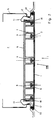
- the air duct floor 100 consists of a section made of plastic formed profile strip 1, the back, i.e. on their the air duct 2 facing side with parallel longitudinal webs 3 formed with a mushroom head 4 on the free web ends is.
- the longitudinal webs 3, of which e.g. as shown five available are spaced apart.
- the two outer longitudinal webs only have half a mushroom head 4.
- the air duct floor 100 is composed of two axially juxtaposed profile strips 1, the can have a length of up to 5.5 m together.
- the Profile bar 1 transverse retaining elements 6 are provided. These holding elements 6, which is e.g. Have 30 mm and as plastic injection molded parts can be trained, are in a row by far determined in succession on the profile bar 1. To fix on the profile strip 1, the holding elements 6 have molded clip arms 7 with rear locking lugs 8, whereby the mushroom heads 4 overlapping Fastening receptacles 9 are formed. To the from the profile bar 1 and the holding elements 6 existing unit in a particularly simple Way by a clip or snap connection on the air duct housing To be able to set, each holding element 6 has at the ends Plug-in receptacles 10, which are equipped with spring clips 11 on. These spring clips 11 are intended to edge edges 12 of the Air duct 2, which limit the opening of the duct floor (Fig. 2).
- Edge areas of the profile strip 1 overlap the channel floor opening boundary edges 12 of the air duct 2. Grooves 13 in the edge areas of the profile strip 1 take sealing cords 14 to achieve a seal against the air duct housing 5.
- the profile strip 1 is also a support for various installation elements in the form of fans 15, reading lights 16, switches 17 u. Like. provided.
- Fig. 3 illustrates that for each individual installation element a separate receiving opening 18 is provided in the profile strip 1 is.
- the receiving openings 18 can before mounting the profile strip 1 in this be introduced, as well as the arrangement of the individually to be determined Installation elements and their electrical wiring before Profile strip assembly can be done.
Landscapes
- Engineering & Computer Science (AREA)
- Mechanical Engineering (AREA)
- Physics & Mathematics (AREA)
- Thermal Sciences (AREA)
- Duct Arrangements (AREA)
Description
- Fig. 1
- eine Ansicht des Deckenluftkanals in Richtung des Pfeils I in Fig. 2 gesehen,
- Fig. 2
- einen Schnitt, folgend der Linie II-II in Fig. 1 und
- Fig. 3
- einen Schnitt, folgend der Linie III-III in Fig. 1.
Claims (4)
- Deckenluftkanal, insbesondere für Omnibusse, mit einem Luftkanalboden (100), der Öffnungen (18) zur Aufnahme von Einbauelementen, wie Lüfter (15), Leuchten (16) u. dgl. aufweist und mit Federklammern (11), die Randkanten (12) des Luftkanals (2), die die Kanalöffnung begrenzen, zu hinterschnappen vermögen, dadurch gekennzeichnet, daß der Luftkanalboden (100) aus zwei axial aneinandergesetzten, aus Kunststoff bestehenden Profilleisten (1) gebildet ist,daß die Profilleisten (1) mehrere, rückseitig angeformte Längsstege (3) aufweisen, welche parallel jedoch zueinander beabstandet verlaufen und jeweils mit einem etwa pilzförmigen Querschnitt ausgebildet sind,daß an den Längsstegen (3) mehrere untereinander einen Abstand wahrende, die Profilleisten (1) querende Halteelemente (6) mit die Pilzköpfe (4) der Längsstege (3) übergreifenden Befestigungsaufnahmen (9) angeordnet sind unddaß die Halteelemente (6) an ihren den Rändern der Profilleisten (1) benachbarten Enden mit den Federklammern (11) bestückt sind.
- Deckenluftkanal nach Anspruch 1, dadurch gekennzeichnet, daß die den Luftkanalboden (100) bildende Profilleiste (1) etwa in der Längsmitte getrennt ist.
- Deckenluftkanal nach Anspruch 1 oder 2, dadurch gekennzeichnet, daß die Profilleiste (1) mit Randkantenbereichen die die Kanalbodenöffnung begrenzenden Randkanten (12) des Luftkanals (2) überlappt und daß die Profilleiste (1) im Bereich der Überlappungszonen mit Dichtschnüren (14) ausgestattet ist.
- Deckenluftkanal nach wenigstens einem der Ansprüche 1 bis 3, dadurch gekennzeichnet, daß die Halteelemente (6) als Kunststoff-Spritzgußteile ausgebildet sind.
Applications Claiming Priority (2)
| Application Number | Priority Date | Filing Date | Title |
|---|---|---|---|
| DE4414245 | 1994-04-23 | ||
| DE4414245A DE4414245A1 (de) | 1994-04-23 | 1994-04-23 | Deckenluftkanal, insbesondere für Omnibusse |
Publications (2)
| Publication Number | Publication Date |
|---|---|
| EP0678408A1 EP0678408A1 (de) | 1995-10-25 |
| EP0678408B1 true EP0678408B1 (de) | 1998-04-15 |
Family
ID=6516273
Family Applications (1)
| Application Number | Title | Priority Date | Filing Date |
|---|---|---|---|
| EP95101568A Expired - Lifetime EP0678408B1 (de) | 1994-04-23 | 1995-02-07 | Deckenluftkanal, insbesondere für Omnibusse |
Country Status (2)
| Country | Link |
|---|---|
| EP (1) | EP0678408B1 (de) |
| DE (2) | DE4414245A1 (de) |
Cited By (1)
| Publication number | Priority date | Publication date | Assignee | Title |
|---|---|---|---|---|
| DE102006009629A1 (de) * | 2006-03-02 | 2007-10-18 | Happich Interiors Gmbh | Deckensystem für Grossraumfahrzeuge oder -flugzeuge |
Families Citing this family (12)
| Publication number | Priority date | Publication date | Assignee | Title |
|---|---|---|---|---|
| DE19641062A1 (de) * | 1996-10-04 | 1998-04-09 | Happich Fahrzeug & Ind Teile | Deckenluftkanal |
| DE19704676A1 (de) * | 1997-02-07 | 1998-08-13 | Man Nutzfahrzeuge Ag | Luftkanal eines Omnibusses |
| DE29804637U1 (de) * | 1998-03-14 | 1998-05-28 | Seeber AG & Co., 67547 Worms | Vorrichtung zur Befestigung eines Innenverkleidungsteils eines Kraftfahrzeuges |
| DE19831880C1 (de) * | 1998-07-17 | 1999-08-12 | Happich Fahrzeug & Ind Teile | Luftkanal für Großraumfahrzeuge |
| EP1529691A1 (de) * | 2003-11-10 | 2005-05-11 | Goodrich Hella Aerospace Lighting Systems GmbH | Verkleidung für ein Fahrzeug |
| DE102005031875B4 (de) * | 2005-07-07 | 2013-05-29 | Webasto Ag | Dachmodul mit Belüftungskanal |
| DE102007014406B3 (de) * | 2007-03-26 | 2008-04-24 | Airbus Deutschland Gmbh | Versorgungskanal mit einem Luftverteilungssystem für Fahrzeuge, Flugzeug mit einem solchen Versorgungskanal und Verfahren zum Ausbilden eines Versorgungskanals |
| DE102009059091A1 (de) * | 2009-12-18 | 2011-06-22 | Bombardier Transportation GmbH, 10785 | Anordnung zur Befestigung an einer Wagenkasten-Decke eines Großraum-Fahrzeuges zur Personenbeförderung |
| CN102826098B (zh) * | 2011-06-14 | 2016-07-06 | 邦巴尔迪尔运输有限公司 | 用于固定在用于客运的大空间车辆的车厢顶棚上的装置 |
| CN103032949B (zh) * | 2011-09-29 | 2016-09-14 | 广东松下环境系统有限公司 | 顶棚内设换气扇 |
| CN106274731B (zh) * | 2016-08-29 | 2018-07-24 | 山东三岭汽车内饰有限公司 | 一种可以实现个性化布置的汽车内衬装置 |
| CN108189646A (zh) * | 2017-09-05 | 2018-06-22 | 广东韩星健康家居科技有限公司 | 一种公交车用空气自动净化设备 |
Family Cites Families (4)
| Publication number | Priority date | Publication date | Assignee | Title |
|---|---|---|---|---|
| DE4000732A1 (de) * | 1990-01-12 | 1991-07-18 | Daimler Benz Ag | Deckenkanalanordnung in einem omnibus |
| DE4016026A1 (de) * | 1990-05-18 | 1991-11-21 | Happich Gmbh Gebr | Belueftungseinrichtung fuer den innenraum eines fahrzeuges |
| DE4122612C1 (de) * | 1991-07-09 | 1992-10-29 | Mercedes-Benz Aktiengesellschaft, 7000 Stuttgart, De | |
| DE4128234C1 (de) * | 1991-08-27 | 1993-01-14 | Mercedes-Benz Aktiengesellschaft, 7000 Stuttgart, De |
-
1994
- 1994-04-23 DE DE4414245A patent/DE4414245A1/de not_active Withdrawn
-
1995
- 1995-02-07 DE DE59501879T patent/DE59501879D1/de not_active Expired - Fee Related
- 1995-02-07 EP EP95101568A patent/EP0678408B1/de not_active Expired - Lifetime
Cited By (1)
| Publication number | Priority date | Publication date | Assignee | Title |
|---|---|---|---|---|
| DE102006009629A1 (de) * | 2006-03-02 | 2007-10-18 | Happich Interiors Gmbh | Deckensystem für Grossraumfahrzeuge oder -flugzeuge |
Also Published As
| Publication number | Publication date |
|---|---|
| DE4414245A1 (de) | 1995-10-26 |
| EP0678408A1 (de) | 1995-10-25 |
| DE59501879D1 (de) | 1998-05-20 |
Similar Documents
| Publication | Publication Date | Title |
|---|---|---|
| DE4414245A1 (de) | Deckenluftkanal, insbesondere für Omnibusse | |
| DE19629060A1 (de) | Dachlängsträgeranordnung für Kraftfahrzeuge | |
| DE2725024A1 (de) | Fenstereinheit fuer backofentuer | |
| EP1632635B1 (de) | Türzarge | |
| DE19719783C1 (de) | Gehäuse | |
| DE19548551C2 (de) | Lüftungsklappenanordnung für Kraftfahrzeuge | |
| EP3386834B1 (de) | Gepäckablagenmodul zum aufbau einer gepäckablage in einem schienenfahrzeug | |
| DE69723490T2 (de) | Dachfirstanordnung | |
| DE102010018298B4 (de) | Halteleiste | |
| DE9307502U1 (de) | Gehäuse zur Aufnahme von elektrischen Bauteilen | |
| DE4121013A1 (de) | Verkleidung fuer eine fenster- oder tuersaeule eines kraftfahrzeuges | |
| EP4013656B1 (de) | Befestigung für eine thermische isolierschicht in einem schienenfahrzeug in integralbauweise | |
| DE2110318C3 (de) | Mosaik-Schaltbild | |
| EP0298070A2 (de) | Befestigung für eine Wand-bzw. Deckenverkleidung | |
| EP0933853A1 (de) | Träger zur Aufnahme eines Steckdosenblocks auf einem Sockelleistenkanal | |
| DE2166618C3 (de) | Verbindungsprofil zum Verbinden zweier Ränder bei Fensterverglasungen o.dgl | |
| DE3614352A1 (de) | Werbe- oder preistafel | |
| EP2182600A2 (de) | Leitungsführungskanal mit bündigem oder versetztem Deckelversatz | |
| EP1279791A1 (de) | Absenkbare Türdichtung | |
| DE2046433C3 (de) | Abdeckplatte für mit elektrischen, pneumatischen hydraulischen o.dgl. Geräten bestückte Verteilungen | |
| DE69420798T2 (de) | Fernsprechverteilerleiste | |
| DE8810098U1 (de) | Befestigungsvorrichtung für Schriftträger | |
| EP0907943B1 (de) | Steckrahmen für kennzeichnungsschilder | |
| DE19501732C2 (de) | Paneel zur Abdeckung bzw. Verkleidung | |
| EP0948922A2 (de) | Gardinenlaufschiene |
Legal Events
| Date | Code | Title | Description |
|---|---|---|---|
| PUAI | Public reference made under article 153(3) epc to a published international application that has entered the european phase |
Free format text: ORIGINAL CODE: 0009012 |
|
| AK | Designated contracting states |
Kind code of ref document: A1 Designated state(s): BE DE FR GB IT NL |
|
| 17P | Request for examination filed |
Effective date: 19951220 |
|
| RAP1 | Party data changed (applicant data changed or rights of an application transferred) |
Owner name: BECKER GROUP EUROPE GMBH |
|
| 17Q | First examination report despatched |
Effective date: 19961216 |
|
| RAP1 | Party data changed (applicant data changed or rights of an application transferred) |
Owner name: HAPPICH FAHRZEUG- UND INDUSTRIETEILE GMBH |
|
| GRAG | Despatch of communication of intention to grant |
Free format text: ORIGINAL CODE: EPIDOS AGRA |
|
| GRAG | Despatch of communication of intention to grant |
Free format text: ORIGINAL CODE: EPIDOS AGRA |
|
| GRAH | Despatch of communication of intention to grant a patent |
Free format text: ORIGINAL CODE: EPIDOS IGRA |
|
| GRAH | Despatch of communication of intention to grant a patent |
Free format text: ORIGINAL CODE: EPIDOS IGRA |
|
| GRAA | (expected) grant |
Free format text: ORIGINAL CODE: 0009210 |
|
| AK | Designated contracting states |
Kind code of ref document: B1 Designated state(s): BE DE FR GB IT NL |
|
| ITF | It: translation for a ep patent filed | ||
| ET | Fr: translation filed | ||
| REF | Corresponds to: |
Ref document number: 59501879 Country of ref document: DE Date of ref document: 19980520 |
|
| GBT | Gb: translation of ep patent filed (gb section 77(6)(a)/1977) |
Effective date: 19980513 |
|
| NLR4 | Nl: receipt of corrected translation in the netherlands language at the initiative of the proprietor of the patent | ||
| PLBE | No opposition filed within time limit |
Free format text: ORIGINAL CODE: 0009261 |
|
| STAA | Information on the status of an ep patent application or granted ep patent |
Free format text: STATUS: NO OPPOSITION FILED WITHIN TIME LIMIT |
|
| 26N | No opposition filed | ||
| PGFP | Annual fee paid to national office [announced via postgrant information from national office to epo] |
Ref country code: FR Payment date: 20000112 Year of fee payment: 6 |
|
| PGFP | Annual fee paid to national office [announced via postgrant information from national office to epo] |
Ref country code: NL Payment date: 20000117 Year of fee payment: 6 |
|
| PGFP | Annual fee paid to national office [announced via postgrant information from national office to epo] |
Ref country code: GB Payment date: 20000120 Year of fee payment: 6 |
|
| PGFP | Annual fee paid to national office [announced via postgrant information from national office to epo] |
Ref country code: DE Payment date: 20000203 Year of fee payment: 6 |
|
| PGFP | Annual fee paid to national office [announced via postgrant information from national office to epo] |
Ref country code: BE Payment date: 20000208 Year of fee payment: 6 |
|
| PG25 | Lapsed in a contracting state [announced via postgrant information from national office to epo] |
Ref country code: GB Free format text: LAPSE BECAUSE OF NON-PAYMENT OF DUE FEES Effective date: 20010207 |
|
| PG25 | Lapsed in a contracting state [announced via postgrant information from national office to epo] |
Ref country code: BE Free format text: LAPSE BECAUSE OF NON-PAYMENT OF DUE FEES Effective date: 20010228 |
|
| BERE | Be: lapsed |
Owner name: HAPPICH FAHRZEUG- UND INDUSTRIETEILE G.M.B.H. Effective date: 20010228 |
|
| PG25 | Lapsed in a contracting state [announced via postgrant information from national office to epo] |
Ref country code: NL Free format text: LAPSE BECAUSE OF NON-PAYMENT OF DUE FEES Effective date: 20010901 |
|
| GBPC | Gb: european patent ceased through non-payment of renewal fee |
Effective date: 20010207 |
|
| PG25 | Lapsed in a contracting state [announced via postgrant information from national office to epo] |
Ref country code: FR Free format text: LAPSE BECAUSE OF NON-PAYMENT OF DUE FEES Effective date: 20011031 |
|
| NLV4 | Nl: lapsed or anulled due to non-payment of the annual fee |
Effective date: 20010901 |
|
| REG | Reference to a national code |
Ref country code: FR Ref legal event code: ST |
|
| PG25 | Lapsed in a contracting state [announced via postgrant information from national office to epo] |
Ref country code: DE Free format text: LAPSE BECAUSE OF NON-PAYMENT OF DUE FEES Effective date: 20011201 |
|
| PG25 | Lapsed in a contracting state [announced via postgrant information from national office to epo] |
Ref country code: IT Free format text: LAPSE BECAUSE OF NON-PAYMENT OF DUE FEES;WARNING: LAPSES OF ITALIAN PATENTS WITH EFFECTIVE DATE BEFORE 2007 MAY HAVE OCCURRED AT ANY TIME BEFORE 2007. THE CORRECT EFFECTIVE DATE MAY BE DIFFERENT FROM THE ONE RECORDED. Effective date: 20050207 |