EP0678220B1 - Monture d'antenne pour television par multisatellites - Google Patents
Monture d'antenne pour television par multisatellites Download PDFInfo
- Publication number
- EP0678220B1 EP0678220B1 EP94904219A EP94904219A EP0678220B1 EP 0678220 B1 EP0678220 B1 EP 0678220B1 EP 94904219 A EP94904219 A EP 94904219A EP 94904219 A EP94904219 A EP 94904219A EP 0678220 B1 EP0678220 B1 EP 0678220B1
- Authority
- EP
- European Patent Office
- Prior art keywords
- support
- axis
- shaft
- antenna
- plane
- Prior art date
- Legal status (The legal status is an assumption and is not a legal conclusion. Google has not performed a legal analysis and makes no representation as to the accuracy of the status listed.)
- Expired - Lifetime
Links
Images


Classifications
-
- H—ELECTRICITY
- H01—ELECTRIC ELEMENTS
- H01Q—ANTENNAS, i.e. RADIO AERIALS
- H01Q3/00—Arrangements for changing or varying the orientation or the shape of the directional pattern of the waves radiated from an antenna or antenna system
- H01Q3/02—Arrangements for changing or varying the orientation or the shape of the directional pattern of the waves radiated from an antenna or antenna system using mechanical movement of antenna or antenna system as a whole
- H01Q3/08—Arrangements for changing or varying the orientation or the shape of the directional pattern of the waves radiated from an antenna or antenna system using mechanical movement of antenna or antenna system as a whole for varying two co-ordinates of the orientation
-
- H—ELECTRICITY
- H01—ELECTRIC ELEMENTS
- H01Q—ANTENNAS, i.e. RADIO AERIALS
- H01Q1/00—Details of, or arrangements associated with, antennas
- H01Q1/12—Supports; Mounting means
-
- H—ELECTRICITY
- H01—ELECTRIC ELEMENTS
- H01Q—ANTENNAS, i.e. RADIO AERIALS
- H01Q1/00—Details of, or arrangements associated with, antennas
- H01Q1/12—Supports; Mounting means
- H01Q1/125—Means for positioning
Definitions
- the present invention relates to an antenna mount for direct television by geostationary satellites.
- the satellites are geostationary, that is to say fixed with respect to the earth and to optimize the possibility of reception, that is to say multiply the possibilities of reception of emissions, the antenna mount makes it possible to point successively the satellites to receive their respective broadcasts.
- the orbit is geostationary in the plane of the equator, centered in the center of the earth and with a radius of 42,164 km, i.e. an altitude above the surface of the earth of 35,786 km for a diameter of earth at the equator of 12 756 km.
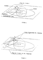
- Figure 1 shows the description of the problem posed defining the earth, the plane of the equator, the equator, the center (O) of the earth, the location (M) of the location of the antenna, the vertical (MO) of the location of the antenna and the latter.
- multisatellite mounts are either provided with two motors allowing, either by successive trial and error, or by computer program and memorization specific to the location of the station, to point exactly at the different satellites, or single engine but with a approximate follow-up.
- the former are very expensive and therefore reserved for professional use for very large antennas.
- the second are based on two different mechanisms.
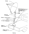
- the first ( Figure 2) is to define the vertical of the location and rotate the antenna around this axis: the axis of the antenna is moves in a plane perpendicular to the vertical (MO) of the location and cuts the orbital plane along a straight line (D ').
- the aim of the satellites is therefore very approximate and only very poorly receives satellites, located in the vicinity of the radial plane of the earth containing the axis of the poles and the location of the station.
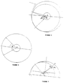
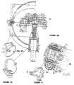
- the second mechanism Figure 3 consists of defining the same elements but inclining, in the meridian plane, the axis of articulation and rotation of the antenna by an angle complementary to the latitude of the location, so that this axis is perpendicular to the plane of the equator and to incline the axis of the antenna with respect to this axis of rotation so that the beam of the antenna describes a cone of revolution whose center of the base in the plane of the equator is the projection of the location on the plane of the orbit.
- the intersection of the scanning of this beam and the orbital plane is therefore a circle offset from the center of the earth.
- the aim is more precise but becomes too false when we want to target a satellite a little lower on the horizon, which requires larger antennas and the angles to be displayed are specific to the location of the station ( figure 5).
- the aiming error is such that it leads to either oversize the diameters of the parabolic antennas , either to use very fine and expensive electronics, or to agree to be able to receive only certain transmissions correctly by selecting the targeted satellites in a low amplitude beam.
- countries which are not facing certain satellites are deprived of broadcasts, very large countries (US, USSR, China, India ...) or areas of influence of languages or interests (French-speaking Africa, Muslim countries for religion, Japan and South East Asia for culture, etc.) are required either to be unable to communicate or to have to multiply the direct television satellites; the same is true for professional telecommunications satellites.
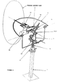
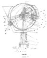
- the present invention overcomes these drawbacks. Indeed, it allows, with a single motor, to target the orbit exactly, to display an angle specific to the latitude of the location of the antenna and to have its own rotations to target the different satellites independent of the location installation location ( Figure 6).
- the antennas can be of smaller dimensions, the installation is much simpler and easy to carry out, the mount can be equipped with a pre-programming made in factory since independent of the place and the installation can be practiced by an individual without training or measuring devices when at present the intervention of a professional laying specialist is necessary.
- the process used to achieve this objective is as follows.
- the antenna beam must describe, in the plane of the equator, a circle which is the geostationary orbit of direct television satellites.
- the antenna beam must therefore be constantly a generator of an oblique cone from the top of the location of the station, from an oblique axis to the vertical of this place passing through the center of the earth and for directing in the plane. from the equator the geostationary orbit.
- the director of this cone in this plane is a circle centered at the intersection of this plane with the vertical of the location of the station and of proportional radius, so that the two cone portions, that defined from the geostationary orbit and limited between this orbit and the vertex and that limited between the plane parallel to the plane of the equator and the vertex are homothetic of center the vertex and of ratio that of the radius of the earth divided by the distance vertex from the cone point of intersection of the plane parallel to the plane of the equator with the vertical of the location; the homothety can be positive or negative (Figure 4).
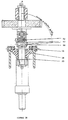
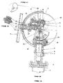
- a vertical axis is formed on the frame by fixing a post (1) and a fine adjustment system (4).
- a axis (D) is rotated around an axis normal to the meridian plane by an angle equal to the angle complementary to the latitude of the place of installation of the antenna so that this axis (D ) or perpendicular to the plane of the equator.
- a point (B) linked to this axis (D), turning around it describes a homothetic circle of the geostationary orbit.
- this line (AB) is indeed a generator of the oblique cone defined in the previous paragraph. If the parabola is said to be “offset”, that is to say if its plane of attachment is not normal to the axis of symmetry of the paraboloid of infinite revolution in which the antenna is taken but oblique, it is necessary that this plane has a reverse inclination on the frame to bring this next axis (AB) or parallel to it. Mainly in the case of antenna "offset”, it is very important that a plane of the antenna, that of symmetry for example, always remains parallel to itself during displacements.
- the antenna support must have only two rotations, for example a vertical and a horizontal perpendicular to the plane of symmetry of the antenna, instead of three; this is more logical anyway since two rotations allow to define a line in space.
- the link between the antenna support and the arm (BM) must allow three rotations free composition of the two rotations of the right (AB) and that around the right (D) as well as a translation since the triangle (AMB) is deformable with two sides of fixed length (AM and BM) and a variable angle (ABM).
- Such a mount therefore has only two adjustments to be made: place the axis of rotation of the straight line (D) in the meridian plane of the installation layout plane, adjust the inclination of (D) at an equal angle in addition to the latitude of the location.
- the adjustment in the meridian plane can be facilitated by carrying out this adjustment on the reception of a satellite after having "displayed" the theoretical angle of this one by turning the mount around the vertical of the place of installation and by immobilizing this movement right after.
- the setting is designed so that it is obtained, after materializing the vertical of the location, by displaying the desired angles, either using a vernier or other mechanical and visual means, or using '' a stepper or resolver motor by using a computer meter without special devices so that such a product can be sold in supermarkets.
- Antenna mount for direct television by satellites characterized by a mechanism allowing the antenna beam to describe an oblique cone having for apex the place of installation of the installation, for oblique axis the vertical of this place passing through the center from the earth and the geostationary orbit of satellites as director; for this the frame has an axis adjusted vertically on which are materialized two fixed points, one being (A) the top of the cone and the other a point (M) located at a distance (d) from it defining a homothetic ratio equal to (d) divided by the radius of the earth, an axis (D) passing through (M) and being able to be inclined in the meridian plane by an angle complementary to that of the latitude of the place of installation of the station and around which an arm (MB), of length (r) such that (d) and (r) are respectively proportional to the radius of the earth and to the radius of the geostationary orbit, rotates thus describing a circle ( C) centered in (M), in a parallel
- the terminal displacement control members are produced by worm-wheel systems whose gear ratios and modules allow a reduction precise enough to obtain pointing precision by simple display of the rotation of the screws, an irreversibility and a mechanical strength of the teeth sufficient to withstand exceptional winds of 160 km / h, either alone or supplemented by an immobilizer.
- the mount simply has three adjustments, one is the verticality adjustment of the shouldered axis (3) forming the straight line (AM), the other the orientation of the plane of symmetry of the mount in the meridian plane of the place d location of the station, the last one is the elevation adjustment at a complementary angle to the latitude of the location of the station, these adjustments are simple and do not require any special equipment except those supplied with the mount because the mechanism is adjusted in the factory (AM) in the extension of the stepped axis and the fine adjustment in the Meridian plane is produced after pointing and focusing on a satellite.
- AM factory
- the frame is protected by a system of casings reducing wind resistance, protecting the dangerous parts of the mechanism and ensuring a sufficient seal to guarantee the achievement of these specifications.
- the vertical axis consists of a post (1), which can be installed in a garden, on a roof, on a balcony or a facade, having a collar at its upper part in which are three tapped holes at 120 ° one others on a circle all around the post and a tapped hole in the center, of a mounting frame proper (4) comprising four smooth holes adapting to the four tapped holes of the post and three tapped holes so that using three pressure screws screwed into the threaded holes of the support, you can vary the orientation of the mount support and immobilize this support on the post using four assembly screws that screw into the four holes of the post, this support has a bore calibrated so that it achieves a removable pivot connection with the antenna mount and it is this axis which is adjusted vertically or at a corrective angle, the mount can be secured to this support with the 'help a stepped axis adjusting in the bore of the support and locked in position using for example a pressure screw, a pinch, tangent
- a precision level-compass (5) a bubble level of circular shape with radius of curvature at the level of the bubble such that it allows to appreciate the 1 / 100th of a degree (radius greater than or equal to 1.5m) containing a magnetic float forming a compass, this level applies, by its underside, on the flange of the post to make a rough adjustment and on the bearing face in the antenna support of the stepped axis of the mount itself, this face and the bore of the support being perfectly perpendicular, circular and graduated marks on the upper face of the transparency of the level ensure the possibility of "tilting" the verticality of the axis of the bore of the antenna support, in the meridian plane of the place d implantation of the i Installation of a corrective angle to take account of the Earth's geoid for fine adjustment.
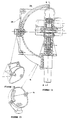
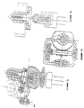
- connection between the dish support and the frame is made by two articulations, one with a vertical axis between the shouldered axis (3) of the frame itself and collinear with it and an intermediate piece called a yoke (6 ), the other in yoke (24) between the yoke (6) and the dish support (7) with a horizontal axis so that these two axes are concurrent at the point (A) defined above, these articulations can be produced by sealed bearings or ball bearings for example.
- the shouldered axis (3) of the mount has a horizontal axis clevis articulation with the latitude tilt axis (8) of the frame, this axis is concurrent with the axis of the shouldered cylinder of this same part, this point being the point (M) defined above at a distance from the shoulder such that the length (AM) is defined by all of the parts: stepped axis of the frame itself, yoke, parabola support and axis of articulation linking the shouldered axis and the axis of inclination of latitude.
- the axis of inclination of latitude (8, FIG. 11) comprises, with the shouldered axis of the frame proper, a clevis joint defined above and a calibrated shouldered cylinder, forming a pivot for the tracking system (9), this cylinder is perpendicular to the axis of its clevis joint, in the plane of symmetry thereof.
- the monitoring system (9, Figures 10 and 12) has a calibrated and shouldered bore forming with the axis of latitude tilt a pivot connection made using bearings or bearings for example and a slide (10) d 'perpendicular axis of the tracking system (7) and whose plane of symmetry contains it for receiving the ball joint support (11) forming the connection (B) defined above.
- the ball joint support (11, Figures 13 and 10) forming the connection (B) has a slider which is received in the slide of the adjustable tracking system and can be immobilized in position, a bore parallel to the slider and in the plane of symmetry of that -this receiving a hollow ball joint (12, Figure 10) made specially, or commercially, such that the center of the ball joint is at a distance parallel to the pivot axis of inclination axis of zero latitude from the axis of the connection in clevis of this axis with the shouldered axis of the mount itself and at a distance perpendicular to this pivot and in the plane of symmetry of the tracking system such that the ratio (AM) / (BM) is equal to the ratio radius of the earth divided by the radius of the geostationary orbit.
- the satellite dish support (7) has in its plane of symmetry, perpendicularly and concurrently, a calibrated bore receiving a calibrated axis (13) forming with it a total removable link, this axis slides freely in the bore of the hollow ball joint defined above, a parabola fixing platform parallel to the axis of the yoke of this support and whose inclination relative to the plane formed by the axis of this yoke and the calibrated bore of this support is either a fixed angle equal to 90 ° for symmetrical parabolas or an angle equal to the "offset" angle for so-called “offset” parabolas, or has a pivot with an axis parallel to the axis of the yoke of this dish support then receiving a specific adaptation to the type of dish used, a support surface for this adaptation and a locking and adjustment device thereof.
- the device for tilting the tilt axis is produced using a worm-wheel system (14, FIG. 10), the reduction of which combined with a vernier linked to the screw allows the display of an accuracy of the order of 1 / 100th of a degree, this system is irreversible and completed by a locking screw in position (15) making it possible to absorb a large part of the effects of bad weather on the antenna so that, for a small footprint, resistance and holding in position are great, the mount is adjusted at the time of assembly in the factory so that the pivot of the tilting device is parallel to the stepped axis of the antenna mount properly said.
- the displacement control of the tracking system relative to the tilt axis is carried out using a worm-wheel output device (16) whose wheel is integral with the tilt axis and the screw has with the tracking system a pivot link, a reducer (17), either with gears, or a second worm-wheel system whose input member is a stepper motor (18) whose casing is linked to the tracking system such that a rotation of one step of the motor corresponds to an angle of rotation of the tracking system relative to the tilt axis, preferably less than 1 / 100 th of a degree.
- connection (B) between the tracking system and the dish support can be achieved by means of two perpendicular pivot connections (19) between them, one horizontal perpendicular to the axis of rotation tracking the axis of inclination and perpendicular to its plane of symmetry with an intermediate part, the other with a perpendicular axis, vertical in the horizontal position of the antenna beam between this intermediate part and a so-called compatibility axis, this axis is pierced with a horizontal hole, perpendicular to the pivot axis of the tracking system, all these axes being concurrent at the theoretical point (B) in the plane of symmetry of the tracking system thus achieving a connection having three degrees of freedom in rotation and one in following translation (MB) ( Figures 31, 32, 33).
- the axis of compatibility defined in the preceding paragraph is provided with a sliding connection normal to the axis of rotation of the tracking system and whose sliding axis is in the plane of symmetry of this system with a calibrated axis, of complementary shape having a pivot connection with the part called dish support, the dish is then totally linked to this axis calibrated by means of a standard support totally linked to this axis and adaptations specific to each brand and dimension of dish ( Figures 9, 31, 32, 33).
- the homothesis in question can be positive or negative, which implies that if it is positive, the theoretical point (A) is above the theoretical point (M) and that the connection (B) is situated on the same side as the parabola with respect to the vertical (AM) constituted by the axis of rotation of the yoke (6) with respect to the shouldered axis (3), in the case of a negative homothety, (M) is above (A) and the connection (B) and the parabola are arranged on either side of the vertical (AM).
- the rollover ensuring at the same time safety with respect to children, adults and domestic animals, the reduction of the catch in the wind, the protection of the mechanism against bad weather, plant and small animal debris (insects, ...), is generally spherical in shape, the center of which is located at point (A) of the mechanism, in two hollow hemispheres (20 and 21), one of which snaps into place.
- the dish support has a spherical part (24) covering the opening made in the hood to ensure a seal with clearance and baffle between the hood and itself.
- the cowling is of generally spherical shape as previously but includes, in addition to the protection offered by the dish support, a second cowl inside the first, in the form of a portion of a sphere, linked to the boss of the tracking support allowing the support-ball joint connection so as to make a double sealing baffle, the amplitude of the portion of the sphere is such that the opening of the cover main is constantly "plugged".
- the cowling consists of a main cover of generally spherical shape, supplemented by a tunnel shape coming to be fixed on the parabola support, this cover has a wide opening with internal collar, in this cover, an intermediate cover of spherical shape slides freely and has at its lower part a wide opening with internal flange and at its upper part an external flange, in this second cover, a third, of spherical shape is housed on the shouldered axis of the frame by a tight or glued boss and an external flange so that the relative movements of these covers are driven by their respective flanges and that the amplitudes of the movements are compatible with the possibilities of the covers, the center of the spheres of these covers coincides with point (A) of the mechanism.
- the cowling in a variant, consists of an external cover in two parts, the upper one remains spherical extended by a tunnel shape coming to be fixed on the parabola support, the other which is linked to it by screws or clipping is semi-spherical and has a large lower opening allowing the relative deflections of the parts, an inner cover linked to the axis supported by a tight or glued boss, of spherical shape, constantly covers the lower opening of the external cover to ensure sealing, the centers of the spheres coincide with point (A) of the mechanism.
- the shouldered axis can be deflected and in two parts rigidly linked together so that the rollover can be achieved by means of an external cover in two semi-spherical parts linked together by screws or snap-fastening, the part close to the parabola is provided with a boss coming to be fixed by tightening or gluing on the end part of the stepped axis, the other half-cover has a large opening allowing the passage of the calibrated axis forming the connection (B), a second spherical inner cover, connected by tightening or bonding to the tracking support by a boss at the level of the ball joint constantly closes the opening of the external cover during the relative movements different elements of the mechanism to seal it by narrow passage, the center of these covers is at point (M) of the mechanism, the dish support can have, to link the boss carrying the axis of ball joint, clevis connection bosses and the parabola fixing plate an external spherical shape ensuring the
- the rollover can be produced by a spherical cover in two parts connected to each other by screws or snap-fastening, the lower part of which comprises a boss coming to be housed in the vertical axis of the yoke and linked to it by screws, tightening or gluing and a light-shaped opening in the plane of symmetry of the mechanism to allow the passage of the calibrated axis forming with the ball joint the connection (B), this light receives a cover leaving the passage of this axis and its form of connection with the other functional surfaces of the dish support, the center of this cover is at point (A) of the mechanism.
- Rubber seals in the form of flexible bellows for rotation, translation, cylindrical or helical can be installed to improve the tightness and complete it in case of part of mechanism external to the covers.
- the architecture of the entire mechanism can be: either internal to the cowling, or the yoke and its connections are external to the cowling.
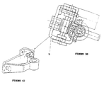
- the parabola is fixed by adaptation pieces according to the different models of parabolas, these adaptation pieces have a single fixing by four screws on an "offset" tilt support articulated along an axis parallel to the axis of the fork-dish support, adjustable and immobilizable in position on a plane of the dish support normal to the plane defined by the calibrated axis forming with the ball joint the connection (B) and the axis of the fork connection- dish support and normal to the plane of symmetry of the mechanism.
- the adaptation pieces specific to each antenna are finely adjusted relative to the dish support plate by means of screws or shims of variable thicknesses inserted around the upper screws of the fixing of these adaptations to compensate for the manufacturing defects of the elements.
- the mount has scales of overall dimensions or of certain elements only to adapt in terms of resistance as well as aesthetics, motorization, ... to the different dimensions of satellite dishes.
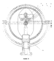
- a first variant ( Figures 17 and 18) is characterized by a positive homothety.
- a mast (23), fixed in a garden, on a balcony, on a roof or along a vertical wall is adjusted approximately vertical by means of a level provided and described in another configuration.
- the support (21) proper is finely adjusted by means of three pressure screws (25) and the level of precision, the reading sensitivity of which is around 0.01; this support is then fixed to the mast using three fixing screws (22).
- the elevation support axis (18) is then oriented well vertically with respect to the ground.
- This axis has a pivot link with the support (21) which can be made total using the pressure screw (26).
- This fixed axis (18) carries, on the one hand the yoke (16) and, on the other hand the azimuth tracking support (33) and its adjustment by the worm (29).
- the yoke (16) has a pivot connection with the axis (18) produced, for example, using two self-lubricating bearings (19) and is articulated on the antenna support (15) by means of the two hinge pins (5).
- the elevation adjustment system consists of a gear (28) toothed and meshing on a worm (29) linked to the azimuth tracking support (33) by a pivot link; these elements rotate around the axis (13), linked to the axis (18), and placed in the center of the toothed wheel (28).
- This locking device is completed by a screw for holding in position (12) avoiding any vibration and reinforcing the resistance of this device to the wind resistance of the installation.
- the azimuth tracking support (33) carries, by a pivot link produced using two self-lubricating bearings for example, the reduction motor support (34) as well as a toothed wheel (36) totally linked to (33).
- the motor (35) is a stepping motor whose power must allow maneuvering in a wind of 110Km / H. It includes a gear reducer and an output worm (37) which meshes with the wheel (36).
- the system is irreversible, which makes it possible to differentiate the boundary conditions of the wind authorizing the maneuver 110 Km / H and of resistance of the antenna under the influence of the wind 160Km / H.
- the motor support (34) has, with the antenna support (15), by means of the rod (8) linked thereto, a ball joint and sliding pivot (10) ensuring the movement of the antenna.
- the parts (23, 21, 18, 28) are always fixed.
- the parts (29), (33), (36) are adjusted in azimuth and are then fixed by the double device (28, 29) and the screw (12).
- the yoke (16) rotates around the fixed vertical axis (18).
- the elements (34), (35), (37) rotate around the axis of (33).
- the antenna support (15) has a combined movement of rotation relative to the yoke (16) and of translation rotation relative to the engine support (34).
- the remote control facing the receiver by remote control, insensitive to dead leaves and various mosses, insensitive to small animals and bad weather, it is necessary to cover the mechanism and make it "waterproof”; this rollover also allows a reduction in the wind resistance, the noises (whistling) of the wind and gives an attractive aesthetic.
- This cowling is therefore essential in the same way as the mechanism itself.
- the rollover given the great disparities in the relative movements of the different parts of the mechanism and the large amplitudes of the said movements, is very difficult to set up and a certain number of projects relating to the present patent application filing differ in this rollover.
- the cowling consists of two hemispheres (17) and (27).
- the cover (17) is linked to the yoke (16) by a slightly “hard” fitting on the cylindrical part thereof and has an internal diameter allowing the movement of the reducing motor support (34); this cover (17) rotates around the elevation support axis (18) and has a radial slot allowing the passage and the clearance of the rod (8) and the boss of the antenna support (15) allowing the fixing of this rod.
- the cover (27) is centered and snapped onto the cover (17) and is therefore easily removable.
- the antenna support (15) has a "tail” in the plane of the groove and wider than the latter to ensure “sealing" of this groove. To complete this seal, seals (7) and (20) ensure that moisture does not come into contact with the functional surfaces of the mechanism.
- the center of the various covers is located at the intersection of the axes (5) and (8) carried by the antenna support (15).
- the fixing the antenna on the antenna support (15) is perpendicular to the axis of the rod (8) or inclined by the angle "offset" with respect thereto.
- the engine must withstand the most severe weather conditions and the materials used are determined by their mechanical characteristics but above all for their ability to withstand bad weather and contact with each other.
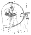
- a second variant ( Figures 19 and 20) is characterized by negative homothety.
- a mast (3) fixed in a garden, on a balcony, a roof or along a vertical wall, is adjusted approximately vertical by means of a level provided and described in another configuration.
- the support (7) proper is finely adjusted by means of three pressure screws (1) and the level of precision whose reading sensitivity is of the order of 0.01 °; this support is then fixed to the mast using three fixing screws (6).
- the elevation support axis (10) is then oriented well vertically with respect to the ground.
- This axis has a pivot link with the support (7) which can be made total using the pressure screw (5).
- This fixed axis (10) carries, on the one hand the yoke (27) and, on the other hand the azimuth tracking support (17) and its adjustment by the worm (44).
- the yoke (27) has a pivot connection with the axis (10) produced, for example, using two self-lubricating bearings (4) and is articulated on the antenna support (22) by means of the two hinge pins (40).
- the elevation adjustment system consists of a gear (37) toothed and meshing on an endless screw (44) linked to the azimuth tracking support (17) by a pivot link; these elements rotate around the axis (32), linked to the axis (10), and placed in the center of the toothed wheel (37).
- This locking device is completed by a screw for holding in position (35) avoiding any vibration and strengthening the resistance of this device to the wind resistance of the installation.
- the azimuth tracking support (36) carries, by a pivot link produced using two self-lubricating bearings, for example, the reduction motor support (17) as well as a toothed wheel (37) totally linked to (36) .
- the motor (21) is a stepping motor whose power must allow maneuvering in a wind of 110Km / H, it includes a gear reducer and an output worm gear meshing on the wheel (37).
- the motor support (17) has, with the antenna support (22), by means of the rod (20) linked thereto, a ball joint and sliding pivot (18) ensuring the movement of the antenna.
- the parts (3, 7, 10, 16) are always fixed.
- the parts (37), (36), (46) are adjusted in azimuth and are then fixed by the double device (37, 21) and the screw (35).
- the yoke (27) rotates around the fixed vertical axis (10).
- the elements (21, 18, 17) rotate around the axis of (36).
- the antenna support (22) has a combined movement of rotation relative to the yoke (27) and of translation rotation relative to the engine support (17).
- the cowling consists of two hemispheres (11) and (45).
- the cover (45) is linked to the orientation support axis (10) by a slightly “hard” fitting on the cylindrical part thereof and has an internal diameter allowing the movement of the reducing motor support (21).
- the cover (11) centers and fits by clipping onto the cover (45) and is therefore easily removable and has a large opening allowing the passage of the various elements.
- the inner cover (12) centers and fits onto the engine support (17) to ensure the closing of the openings necessary for the deflections of the elements relative to the housings (11) and (45).
- a seal (19) seals between the reducing motor support (17) and the antenna support (22).
- the center of the covers is located in the plane of symmetry of the mechanism and on the axis (32).
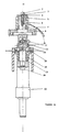
- a third variant ( Figures 21 and 22) is characterized by a positive homothety.
- a mast (23) fixed in a garden, on a balcony, on a roof or along a vertical wall is adjusted approximately vertical by means of a level provided and described in another configuration.
- the support (25) proper is finely adjusted by means of three pressure screws (20) and the level of precision whose reading sensitivity is of the order of 0.01 °; this support is then fixed to the mast using three fixing screws (24).
- the elevation support axis (27) is then oriented well vertically with respect to the ground.
- This axis has a pivot link with the support (25) which can be made total using the pressure screw (19).
- This fixed axis (27) carries, on the one hand the yoke (21) and on the other hand the azimuth tracking support (1) and its adjustment by the worm (8).
- the yoke (21) has a connection pivot with the axis (27) produced for example using two self-lubricating bearings (28) and is articulated on the antenna support (2) by means of the two articulation axes (39).
- the elevation adjustment system consists of a gear (18) toothed and meshing on a worm (17) linked to the azimuth tracking support (40) by a pivot link; these elements rotate around the axis (7), linked to the axis (27) and placed in the center of the toothed wheel (18).
- This locking device is completed by a screw for holding in position (5) avoiding any vibration and strengthening the resistance of this device to the wind resistance of the installation.
- the azimuth tracking support (40) carries, by a pivot link produced using two self-lubricating bearings, for example, the reduction motor support (40) as well as a toothed wheel (3) totally linked to the support part. (1).
- the motor (9) is a stepping motor whose power must allow maneuvering in a wind of 110 km / H. It includes a gear reducer and an output worm (8) which meshes with the wheel (3).
- the system is irreversible, which makes it possible to differentiate the boundary conditions of the wind authorizing the 110 km / H maneuver and the resistance of the antenna under the influence of the 160 km / H wind.
- the motor support (40) has, with the antenna support (2), by means of the rod (36) linked thereto, a ball joint and sliding pivot (33) ensuring the movement of the antenna.
- the parts (27), (25), (23), (18) are always fixed.
- the parts (17), (1), (3) are adjusted in azimuth and are then fixed by the double device (16, 17) and the screw (5).
- the yoke (21) rotates around the axis fixed vertical (27).
- the elements (8), (9), (40) rotate around the axis of the support piece (1).
- the antenna support (2) has a combined movement of rotation relative to the yoke (21) and of rotation-translation relative to the engine support (40).
- the cowling consists of two hemispheres (30) and (31).
- the cover (30) is linked to the axis (27) by a slightly hard fitting on the cylindrical part thereof and has an internal diameter allowing the movement of the reducing motor support (9).
- the cover (31) is centered and snapped onto the cover (30) and is therefore easily removable.
- the engine support (40) has a cylindrical tail in its plane of symmetry allowing the slightly hard fitting of an inner cover (32).
- the cover (31) has a large opening allowing the normal movement of the engine support (40) relative to the fixed axis (27).
- the shape of the cover (31) is conditioned by the constant covering of the opening made in the cover (31) to ensure sealing. To complete this seal, seals (37), (26) and (29) ensure that moisture does not come into contact with the functional surfaces of the mechanism.
- the center of all these covers is located in the plane of symmetry of the mechanism and in the center of the axis (7).
- a fourth variant ( Figures 23 to 26) is characterized by negative homothety.
- a pole (9) fixed in a garden, on a balcony, on a roof or along a vertical wall is adjusted approximately vertical by means of a level provided and described in another configuration.
- the support (1) itself is finely adjusted by means of three pressure screws (10) and the level of precision, the reading sensitivity of which is around 0.01 °. This support is then fixed to the mast using three fixing screws (3).
- the elevation support axis (13) is then oriented well vertically with respect to the ground.
- This axis has a pivot link with the support (1) which can be made total using the pressure screw (7).
- This fixed axis (13) carries, on the one hand the yoke (4) and, on the other hand, the azimuth tracking support (25) and its adjustment by the worm (26).
- the yoke (4) has a pivot connection with the axis (13) produced, for example, using two self-lubricating bearings (2) and is articulated on the antenna support (19) by means of the two hinge pins (30).
- the elevation adjustment system consists of a toothed wheel linked to (13) and meshing on an endless screw (26) linked to the azimuth tracking support (25) by a pivot link; these elements rotate around the axis (37), linked to the axis (13), and placed in the center of the toothed wheel.
- This locking device is completed by a screw for holding in position (34) preventing any vibration and reinforcing the resistance of this device to the wind resistance of the installation.
- the motor (18) is a stepping motor whose power must allow maneuvering in a wind of 110 km / H. It includes a gear reducer and an output worm gear meshing on the wheel (32). So the system is irreversible, which makes it possible to differentiate the boundary conditions of the wind allowing maneuvering 110 km / h and resistance of the antenna under the influence of the wind 160 km / h.
- the motor support (14) has, with the antenna support (19), by means of the rod (16) linked thereto, a ball joint and sliding pivot (15) ensuring the movement of the antenna.
- the parts (9, 1, 13) are always fixed.
- the parts (32, 25, 26) are adjusted in azimuth and are then fixed by the double device (26, 13) and the screw (34).
- the yoke (4) rotates around the fixed vertical axis (13).
- the elements (18, 14, 17) rotate around the axis of (25).
- the antenna support (19) has a combined movement of rotation relative to the yoke (4) and of rotation-translation relative to the engine support (14).
- the cowling consists of two hemispheres (11) and (20).
- the cover (11) is linked to the orientation support axis (13) by a slightly hard fitting on the cylindrical part of the latter and locked by the screws (5). It has an internal diameter allowing the movement of the reducing motor support (18).
- the cover (20) centers and fits by clipping onto the cover (11) and is therefore easily removable and carries a slot allowing the passage of the boss of (19) carrying the axis (16).
- An inner cover (12) is centered and fitted onto the cover (11) to ensure the closing of the slot necessary for the movement of (19).
- a seal (3) seals between the yoke (4) and the support (1).
- the center of the covers is located at the intersection of axes (30) and (13).
- a fifth variant ( Figures 27 and 28) is characterized by negative homothety.
- a mast (32) fixed in a garden, on a balcony, on a roof or along a vertical wall is adjusted approximately vertical by means of a level provided and described in another configuration.
- the support (27) proper is finely adjusted by means of three pressure screws (31). This support is then fixed to the mast using three fixing screws (29).
- the elevation support axis (23, 31) is then oriented well vertically with respect to the ground.
- This axis has a pivot connection with the support (27) which can be made total using the pressure screw (28).
- This fixed axis (23, 31) carries, on the one hand the yoke (18) and, on the other hand, the support followed in azimuth (7) and its adjustment by the worm (11).
- the yoke (18) has a pivot connection with the axis (23, 31) and is articulated on the antenna support (9) by means of the two articulation axes (16).
- the elevation adjustment system consists of a toothed wheel linked to (31) and meshing on an endless screw (11) linked to the azimuth tracking support (7) by a pivot link; these elements rotate around the axis (14), linked to the axis (23, 31), and placed in the center of the toothed wheel.
- This device is locked by a position holding screw (12).
- the azimuth tracking support (7) carries, by a pivot link, the reduction motor support (6) as well as a toothed wheel (8) totally linked to (7) and in which the worm (11) is mounted free to rotate.
- the motor (34) is a stepping motor. It includes a gear reducer and an output worm gear meshing on the wheel (8).
- the engine support (6) has with the antenna support (9), via the rod (32) linked to this, a ball joint and sliding pivot (33) ensuring the movement of the antenna.
- the cowling consists of the elements (25, 26, 24).
- the cover (25) is fitted hard on the axis (23) and has the shape of a portion of a sphere.
- the cover (24) has a spherical base completed by a cylindrical upper part and is fixed on the antenna support (9) using the screws (17).
- the intermediate cover (25) in the form of a portion of a sphere slides both over the covers (24) and (25) during operation in order to seal the mechanism.
- a sixth variant ( Figures 29 and 30) is characterized by negative homothety.
- a mast (32) fixed in a garden, on a balcony, on a roof or along a vertical wall is adjusted approximately vertical by means of a level provided and described in another configuration.
- the support (27) proper is finely adjusted by means of three pressure screws (31). This support is then fixed to the mast using three fixing screws (29).
- the elevation support axis (23, 33) is then oriented well vertically with respect to the ground.
- This axis has a pivot connection with the support (27) which can be made total using the pressure screw (28).
- This fixed axis (23, 33) carries, on the one hand the yoke (18) and, on the other hand, the support followed in azimuth (7) and its adjustment by the worm (11).
- the yoke (18) has a pivot connection with the axis (23, 33) and is articulated on the antenna support (9) by means of the two articulation axes (16).
- the elevation adjustment system consists of a toothed wheel linked to (33) and meshing on an endless screw (11) linked to the azimuth tracking support (7) by a pivot link. These elements rotate around the axis (14), linked to the axis (23, 33) and placed in the center of the toothed wheel. This device is locked by a position holding screw (12).
- the azimuth tracking support (7) carries, by a pivot link, the reduction motor support (6) as well as a toothed wheel (8) totally linked to (7).
- the motor (37) is a stepping motor. It includes a gear reducer and an output worm gear meshing on the wheel (8).
- the motor support (6) has, with the antenna support (9), by means of the rod (34) linked to the latter, a ball joint and sliding pivot (35) ensuring the movement of the antenna
- the cowling consists of the elements (1, 24, 26).
- the cover (26) is fitted hard onto the fixed axis (23) and has a semi-spherical shape.
- the cover (1) linked to the antenna support (9) has a semi-spherical shape supplemented by a prismatic shape.
- the half-spherical cover (24) is centered and fixed on the cover (1) using the screws (17) and has a large opening allowing the support (27) to move relative to the antenna support (9).
- the cover (26) seals this opening.
- a seventh variant ( Figures 31, 32, 33) is characterized by a modification of the different other projects, applicable to all so that the different solutions could be modified.
- the elevation adjustment system is reversed, that is to say that instead of having the toothed wheel linked to the lifting support axis and the worm screw linked by a pivot link to the tracking support in azimuth, it is this which has a pivot connection with the elevation support axis and the gear is linked to the azimuth tracking support.
- the azimuth tracking support has with the antenna support not a sliding ball joint with the rod linked to the antenna support, but a double pivot connection, one normal to the aforementioned rod and perpendicular to the plane of symmetry of the motor support, the other sliding axis that of the rod linked to the antenna support. This allows a significant reduction in costs and a significant reduction in the tilting torques of the antenna under the effect of the wind at the connection of this antenna support in the yoke.
- the reduction gear is defined here as well as the mounting of the worm adjusting and monitoring in azimuth.
- An eighth variant ( Figure 9, 36 to 42) is identical to the project ( Figures 10 to 16) for its structure and general solution but differs in that the connection (B) and the dish support are different.
- the connection (B), parts (11, 13, 12), and calibrated axis is produced as for the seventh variant ( Figures 31, 32, 33) for the whole but the calibrated axis comprises, for example, a longitudinal key forming with the accounting axis (12) a sliding link installing the plane of symmetry of this axis in the plane of symmetry of the monitoring system. So the plane of symmetry of this axis calibrated remains constantly parallel to the axis of rotation of the tracking system, that is to say perpendicular to the common plane of the geostationary orbit of the satellites and the equator.
- the calibrated axis comprises, with an intermediate part (20), a pivot connection, produced for example using two self-lubricating bearings, and is totally linked to the antenna support (7).
- the intermediate piece (20) has a pivot connection with the yoke (6) and has a sealing function for the opening with this yoke as in the project ( Figures 10 to 16).
- Figures 34 and 35 show an example of a two-speed gear reduction motor with output on a worm.
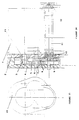
- the antenna mount has a stepped axis (3) which can be finely adjusted vertically by means of an actual mount support (4), a yoke (6) articulated on this axis (3) defines a fixed point.
- (A) by the intersection of its axes, an axis (D) of latitude tilt (8) articulated horizontally at (M) point of the axis (3) and adjusted so as to be perpendicular to the plane of the equator, a monitoring system (9) articulated around (D), carries an annular linear connection (B) with a satellite dish support (7) articulated with the yoke (6), a set of protective and security casings, so that the kinematics of the mechanism reproduces a positive or negative homothety of center (A) with the orbital cone defined by its vertex (A), its axis the vertical of the place of implantation and its director the geostationary orbit of satellites, the ratio (AM / BM) being the same as that radius of the earth-radius of the orbit
- the frame support proper (4) comprises a base receiving the screws for fixing to the post and for adjusting the verticality and a vertical bore receiving the shouldered axis (3)
- the shouldered axis comprises two vertical cylinders of the same axis, one housed in the bore of (4), the other serving as an articulation for the yoke (6), a horizontal bore receiving the axis of rotation of the latitude tilt axis (8) and a housing of the wheel-screw tilting device endless (14)
- the tilt axis (8) comprises a pivot receiving the tracking system (9) which carries the annular linear link (B) and receives the worm-wheel system (16) and its group reduction motor (18)
- the yoke (6) articulated vertically on the axis (3) has a horizontal connection in yoke with the dish support (7) which carries a perpendicular rod and competing with the yoke axis receiving the connection linear annular and a support plane of the adaptation parts specific to each parabola normal to this rod
- the annular linear link between the tracking system (9) and the dish support (7) in (B) can be adjustable in the following position (BM) by means of a fixed slide link to adapt to the actual geoid of the earth by varying the ratio of homothety and by tilting the shouldered axis (3) according to the latitude of the place.
- the tilt adjustment (8) is obtained using a worm-wheel system (14) immobilized by means of a pressure screw (15) and the displacement of the tracking system (9) by means a worm-wheel system (16) controlled by a reduction gear and a controlled rotation motor (18) allowing immobilization and mechanical resistance independent of the motive power ensuring security for gusty winds of 160 km / H and a sufficient reduction to ensure pointing accuracy (1) to 3 / 100th of a degree by simple rotation of the screws or of the motor according to a linear law between the rotation of the screws or of the motor and the rotation of the wheel and the elements which are linked.
- the first is the verticality adjustment of the shouldered axis (3) obtained using a spherical compass level (5) making it possible to appreciate a deviation of 1 / 100th of a degree by three pressure screws between the post and the actual mount support (4) and immobilized by means of four locking screws
- the second is the orientation towards the meridian plane of the location of the plane of symmetry of the frame by means of a rotation of the shouldered axis (3) around the vertically adjusted axis of the bore of the frame support itself (4) and immobilized by means of a pressure screw, pinching, tangent buffers, etc.
- This adjustment is refined by pointing and focusing on a satellite, the latter by displaying the complementary angle of the latitude the location of the latitude tilt axis (8) by means of a worm-wheel system and immobilized using a pressure screw, the mechanism being set to zero in the factory, the axis (D) in the extension of the axis (3), the annular linear link (B) in the plane of symé sorts the frame.
- the casing system consists of two elements of generally semi-spherical shape, linked together by clipping or screwing having for center either (A) and one of them is then linked to the yoke (6), or (M ) and the main casing is then linked either to the yoke (6) or to the stepped axis (3), another sliding casing being linked to the dish support (7).
- Complementary shapes of the other parts, gaskets or bellows, complete the complete closing of the mechanism, ensuring its protection from bad weather, plants and debris, insects and small animals as well as operational protection against people, children or pets.
- the parabola support (7) comprises with the fixing plate of the parabola, a pivot axis connection passing through point (A) of the mount in its plane of symmetry, this plate comprises with the monitoring system (9) a connection with three degrees of freedom: the first of translation along the axis of the pivot previous with the rod, the second of rotation between the rod and the frame of normal axis and concurrent with the previous and the third of rotation between the frame and the system of follow-up (9) of axis forming with the previous ones a rectangular trihedron .
- the mechanism may be entirely internal to the cowling or the yoke and its connections are external thereto.
- the parabola is fixed by means of adaptation parts according to the different models of parabolas, these parts have a single fixing by four fixing screws on an "offset" tilting support articulated along an axis parallel to the axis of the adjustable dish support-screed connection immobilizable in position on a plane of the parabola support normal to the plane defined by the axis of the rod receiving the annular linear connection (B).
- the adaptation parts specific to each parabola are finely adjusted relative to the parabola support plate (7) by means of adjustment screws or shims inserted around the fixing screws of these adaptations to compensate for the manufacturing defects of the parables.
- This new axis of rotation a ⁇ 2 between (9) and (19) is motorized by means of a double wheel-worm reducer coupled to a step motor. not for example, with pulse counting so that the angles of rotation follow a linear law with the rotation of the motor.
- the positioning of the aiming on the orbital cycle is carried out in orthonormal axes by two perpendicular rotations so that the equation of this cycle to carry out the computer programming of this one is extremely simplified.
- the two gearmotor systems of the tracking system (16, 18) and the orbit elevation adjustment (20, 21) are identical to reduce costs and standardize the reference axes of the programming equations.
- the part (19) retains the same connection with the actual antenna support (7) as in the basic device.
- the installation of such an antenna is carried out permanently on a reserved vehicle type "jeep" for example or at least on a base fixed post on a vehicle.
- the upper part of the frame or frame itself can be folded inside the vehicle to "pass" more unnoticed or better circulate on the road or in the middle of crowded places or with heavy vegetation.
- the occupants can be in direct contact with the headquarters, receive plans, documents, operating modes, diagrams of nuclear power plants and key points, images of the objectives. , ..., in order to best fulfill their mission using satellite images emitted from a transmitting cell which itself receives live images from command centers or spy satellites or simply watch their favorite shows.
- This application can be particularly effective in the event of floods, earthquakes, volcanic eruptions, large fires, nuclear accidents, as well as for military uses (Somalia, Yugoslavia, ...) or to take advantage of your holidays.
Description
- La présente invention concerne une monture d'antenne pour télévision directe par satellites géostationnaires.
- Les satellites sont géostationnaires, c'est-à-dire fixes par rapport à la terre et pour optimaliser la possibilité de réception, c'est-à-dire multiplier les possibilités de réception d'émissions, la monture d'antenne permet de pointer successivement les satellites pour recevoir leurs émissions respectives.
- L'orbite est géostationnaire dans le plan de l'équateur, centrée au centre de la terre et de rayon 42164 Km, soit une altitude par rapport à la surface de la terre de 35786 Km pour un diamètre de terre au niveau de l'équateur de 12756 Km.
- La figure 1 montre l'exposé du problème posé définissant la terre, le plan de l'équateur, l'équateur, le centre (O) de la terre, le lieu (M) de l'implantation de l'antenne, la verticale (MO) du lieu d'implantation de l'antenne et celle-ci.
- A l'heure actuelle, les montures multisatellites sont soit pourvues de deux moteurs permettant, soit par tâtonnements successifs, soit par programme informatique et mémorisation propres au lieu d'implantation de la station, de pointer exactement les différents satellites, soit monomoteur mais avec un suivi approché. Les premières sont très chères et réservées ainsi à un usage professionnel pour des antennes de très grandes dimensions. Les deuxièmes sont basées sur deux mécanismes différents.
- Le premier (figure 2) consiste à définir la verticale du lieu d'implantation et à faire tourner l'antenne autour de cet axe : l'axe de l'antenne se déplace dans un plan perpendiculaire à la verticale (MO) du lieu d'implantation et coupe le plan orbital suivant une droite (D'). La visée des satellites est alors très approximative et ne permet de recevoir, et mal, qu'un très petit nombre de satellites situés au voisinage du plan radial de la terre contenant l'axe des pôles et le lieu de la station.
- Le deuxième mécanisme, figure 3, consiste à définir les mêmes éléments mais à incliner, dans le plan méridien, l'axe d'articulation et de rotation de l'antenne d'un angle complémentaire de la latitude du lieu d'implantation, de façon à ce que cet axe soit perpendiculaire au plan de l'équateur et d'incliner l'axe de l'antenne par rapport à cet axe de rotation de sorte que le faisceau de l'antenne décrive un cône de révolution dont le centre de la base dans le plan de l'équateur est la projection du lieu d'implantation sur le plan de l'orbite. L'intersection du balayage de ce faisceau et du plan orbital est donc un cercle décentré par rapport au centre de la terre. La visée est plus précise mais devient trop fausse dès que l'on veut viser un satellite un peu plus bas sur l'horizon, ce qui nécessite de plus grandes antennes et les angles à afficher sont propres au lieu d'implantation de la station (figure 5).
- En effet, dès que l'on vise un satellite faisant un angle de plus de quinze à vingt degrés d'écart par rapport au plan méridien, l'erreur de visée est telle qu'elle conduit, soit à surdimensionner les diamètres des antennes paraboliques, soit à utiliser une électronique très fine et coûteuse, soit à accepter de ne pouvoir recevoir correctement que certaines émissions en sélectionnant les satellites visés dans un faisceau de faible amplitude. Ainsi, les pays qui ne sont pas face à certains satellites sont privés d'émissions, les pays très étendus (U.S., U.R.S.S., Chine, Inde ...) ou les zones d'influence de langues ou d'intérêts (Afrique de langue française, Pays musulmans pour la religion, Japon et Asie du Sud Est pour la culture, ...) sont astreints, soit à ne pouvoir communiquer, soit à devoir multiplier les satellites de télévision directe ; il en est de même pour les satellites de télécommunications professionnels.
- La présente invention permet de remédier à ces inconvénients. En effet, elle permet, avec un seul moteur, de viser exactement l'orbite, d'afficher un angle propre à la latitude du lieu d'implantation de l'antenne et de posséder des rotations propres pour viser les différents satellites indépendantes du lieu d'implantation de l'installation(figure 6). Ainsi les antennes peuvent être de plus petites dimensions, la pose est beaucoup plus simple et facile à réaliser, la monture peut être équipée d'une pré-programmation faite en usine puisqu'indépendante du lieu et l'installation peut être pratiquée par un particulier sans formation ni appareils de mesure alors qu'à l'heure actuelle l'intervention d'un spécialiste poseur professionnel est nécessaire.
- Le procédé utilisé pour réaliser cet objectif est le suivant. Le faisceau de l'antenne doit décrire, dans le plan de l'équateur, un cercle qui est l'orbite géostationnaire des satellites de télévision directe. Le faisceau de l'antenne doit donc être constamment une génératrice d'un cône oblique de sommet le point d'implantation de la station, d'axe oblique la verticale de ce lieu passant par le centre de la terre et pour directrice dans le plan de l'équateur l'orbite géostationnaire. Si l'on coupe ce cône oblique par un plan parallèle au plan de l'équateur, la directrice de ce cône dans ce plan est un cercle centré à l'intersection de ce plan avec la verticale du lieu d'implantation de la station et de rayon proportionnel, de sorte que les deux portions de cône, celui défini à partir de l'orbite géostationnaire et limité entre cette orbite et le sommet et celui limité entre le plan parallèle au plan de l'équateur et le sommet sont homothétiques de centre le sommet et de rapport celui du rayon de la terre divisé par la distance sommet du cône point d'intersection du plan parallèle au plan de l'équateur avec la verticale du lieu d'implantation ; l'homothétie pouvant être positive ou négative (figure 4).
- Le mécanisme de la figure 8 permettant d'atteindre cet objectif est construit selon le modèle général suivant. Un axe vertical est constitué sur la monture par la fixation d'un poteau (1) et un système de réglage fin (4). Sur cet axe, on matérialise deux points fixes (A) et (M). En (M) on fait tourner un axe (D) autour d'un axe normal au plan méridien d'un angle égal à l'angle complémentaire de la latitude du lieu d'installation de l'antenne de sorte que cet axe (D) soit perpendiculaire au plan de l'équateur. Un point (B) lié à cet axe (D), tournant autour de celui-ci décrit un cercle homothétique de l'orbite géostationnaire. On assujettit l'axe de la parabole de l'antenne à passer constamment par les points (A) et (B), cette droite (AB) est bien une génératrice du cône oblique défini au paragraphe précédent. Si la parabole est dite "offset", c'est-à-dire si son plan de fixation n'est pas normal à l'axe du symétrie du paraboloïde de révolution infini dans lequel est prise l'antenne mais oblique, il faut que ce plan ait une inclinaison inverse sur la monture pour ramener cet axe suivant (AB) ou parallèle à celui-ci. Principalement dans le cas d'antenne "offset", il est très important qu'un plan de l'antenne, celui de symétrie par exemple, reste toujours parallèle à lui-même au cours des déplacements. Pour atteindre ce but, le support d'antenne doit posséder deux rotations seulement, par exemple une verticale et une horizontale perpendiculaire au plan de symétrie de l'antenne, au lieu de trois ; ceci est de toutes façons plus logique puisque deux rotations permettent de définir une droite dans l'espace. En (B) la liaison entre le support d'antenne et le bras (BM) doit laisser libre trois rotations composition des deux rotations de la droite (AB) et de celle autour de la droite (D) ainsi qu'une translation puisque le triangle (AMB) est déformable avec deux côtés de longueur fixe (AM et BM) et un angle variable (ABM). Le procédé ainsi défini place le plan de symétrie de l'antenne offset parallèle à la verticale du lieu ; dans le cas où l'on désire que ce plan de symétrie de l'antenne reste constamment normal au plan de l'orbite et radial par rapport à celle-ci, l'axe de compatibilité (AB) est muni d'une liaison glissière normale à l'axe de rotation du système de suivi (MB) avec celui-ci (figure 9).
- Les deux cônes étant homothétiques, les angles de rotation dans le plan de l'équateur autour du centre de la terre pour "passer" d'un satellite à un autre sont les mêmes que ceux du plan normal à la droite (D) de rotation du point (B) autour du point (M) de sorte que les satellites étant fixes par rapport à la terre, les rotations ainsi définies sur la monture sont fixes elles aussi et indépendantes du lieu d'implantation de l'installation (figure 6). On peut alors préprogrammer celles-ci au moment de la fabrication, il ne reste qu'à fixer un zéro au programme en fonction de la longitude d'implantation. Une telle monture ne possède donc que deux réglages à effectuer : placer l'axe de rotation de la droite (D) dans le plan méridien du plan d'implantation de l'installation, régler l'inclinaison de (D) suivant un angle égal au complémentaire de la latitude du lieu d'implantation. Le réglage dans le plan méridien peut être facilité en effectuant ce réglage sur le captage d'un satellite après avoir "affiché" l'angle théorique de celui-ci en faisant tourner la monture autour de la verticale du lieu d'installation et en immobilisant ce mouvement juste après. Le réglage est conçu de telle sorte qu'il s'obtienne, après avoir matérialisé la verticale du lieu d'implantation, en affichant les angles recherchés, soit à l'aide d'un vernier ou autre moyen mécanique et visuel, soit à l'aide d'un moteur pas à pas ou à résolveur par utilisation d'un compteur informatique sans appareils particuliers si bien qu'un tel produit puisse être vendu en grandes surfaces de distribution.
- Dans le cas où l'on souhaite une visée encore plus fine pour tenir compte des défauts de rotondité de la terre, on peut, d'une part incliner (AM), normalement vertical, dans le plan méridien d'un angle correctif très faible et d'autre part, équiper la monture d'antenne d'un réglage fin de la longueur (MB), des tableaux de valeurs sont alors nécessaires mais la qualité de pointage est alors absolument parfaite, hors défaut de pose par l'installateur.
- Monture d'antenne pour télévision directe par satellites caractérisée par un mécanisme permettant au faisceau de l'antenne de décrire un cône oblique ayant pour sommet le lieu d'implantation de l'installation, pour axe oblique la verticale de ce lieu passant par le centre de la terre et pour directrice l'orbite géostationnaire des satellites ; pour cela la monture possède un axe réglé verticalement sur lequel sont matérialisés deux points fixes, l'un étant (A) le sommet du cône et l'autre un point (M) situé à une distance (d) de celui-ci définissant un rapport d'homothétie égal à (d) divisé par le rayon de la terre, un axe (D) passant par (M) et pouvant être incliné dans le plan méridien d'un angle complémentaire de celui de la latitude du lieu d'installation de la station et autour duquel un bras (MB) , de longueur (r) telle que (d) et (r) sont respectivement proportionnels au rayon de la terre et au rayon de l'orbite géostationnaire, tourne en décrivant ainsi un cercle (C) centré en (M), dans un plan parallèle au plan de l'orbite géostationnaire, en installant le faisceau de l'antenne suivant la droite (AB) ou suivant une parallèle à celle-ci, ce faisceau décrit le cône de visée orbital ; le cône oblique défini par le sommet (A), l'axe (AMO) et de directrice le cercle (C) est homothétique du cône orbital dans le rapport (d) divisé par le rayon de la terre, cette homothétie peut être positive ou négative (figure 8).
- Pour tenir compte du géoïde réel de la terre, on définit des tables de valeurs et on incline l'axe vertical dans le plan méridien de manière à ce que celui-ci contienne effectivement le centre de la terre, on incline dans le plan méridien l'axe (D), défini précédemment, d'un angle tenant compte de la latitude réelle du lieu et on règle la longueur du bras (MB) de façon à viser très exactement l'orbite.
- Pour que la monture possède une loi linéaire des rotations par rapport aux commandes et pour assurer l'irréversibilité des mouvements permettant une immobilisation en position de pointage et une résistance au vent indépendantes des organes de commande, les organes terminaux de commandes de déplacement sont réalisés par des systèmes roue-vis sans fin dont les rapports de denture et modules permettent une réduction suffisamment précise pour obtenir les précisions de pointage par simple affichage de la rotation des vis, une irréversibilité et une résistance mécanique des dentures suffisante pour résister à des vents exceptionnels de 160 Km/H, soit seule, soit complétée par un dispositif d'immobilisation.
- La monture possède simplement trois réglages, l'un est le réglage de verticalité de l'axe épaulé (3) formant la droite (AM), l'autre l'orientation du plan de symétrie de la monture dans le plan méridien du lieu d'implantation de la station, le dernier est le réglage d'élévation suivant un angle complémentaire de la latitude du lieu d'implantation de la station, ces réglages sont simples et ne nécessitent aucun matériel spécial hors ceux fournis avec la monture car le mécanisme est réglé en usine (AM) dans le prolongement de l'axe épaulé et le réglage fin dans le plan méridien est réalisé après pointage et mise au point sur un satellite.
- Pour répondre à un cahier des charges très strict en ce qui concerne la sécurité du fonctionnement vis-à-vis d'enfants ou d'animaux domestiques à proximité, de résistance aux intempéries protection du mécanisme vis-à-vis des débris végétaux et des nidations de petits animaux (insectes, oiseaux, ...), la monture est protégée par un système de carters réduisant la prise au vent, protégeant les parties dangereuses du mécanisme et assurant une étanchéité suffisante pour garantir la réalisation de ce cahier des charges.
- Premier exemple de réalisation (figures 11 à 16). L'axe vertical est constitué d'un poteau (1), pouvant être installé dans un jardin, sur un toit, sur un balcon ou une façade, comportant une collerette à sa partie supérieure dans laquelle sont trois trous taraudés à 120° les uns des autres sur un cercle tout autour du poteau et un trou taraudé au centre, d'un support de monture proprement dit (4) comportant quatre trous lisses s'adaptant aux quatre trous taraudés du poteau et trois trous taraudés de telle sorte qu'à l'aide de trois vis de pression vissées dans les trous taraudés du support on puisse faire varier l'orientation de support de monture et immobiliser ce support sur le poteau à l'aide de quatre vis d'assemblage se vissant dans les quatre trous du poteau, ce support comporte un alésage calibré de telle sorte qu'il réalise une liaison pivot démontable avec la monture d'antenne et c'est cet axe qui est réglé verticalement ou suivant un angle correctif, la monture est solidarisable de ce support à l'aide d'un axe épaulé s'ajustant dans l'alésage du support et bloqué en position à l'aide par exemple d'une vis de pression, d'un pincement, de tampons tangents.
- Le réglage de la verticalité du poteau et support d'antenne et la mise en parallèle du plan de symétrie de la monture avec le plan méridien du lieu d'implantation de l'installation sont contrôlés par un niveau-boussole (5) de précision constitué d'un niveau à bulle de forme circulaire à rayon de courbure au niveau de la bulle tel qu'il permette d'apprécier le 1/100ème de degré (rayon supérieur ou égal à 1,5m) renfermant un flotteur aimanté formant boussole, ce niveau s'applique, par sa face inférieure, sur la collerette du poteau pour effectuer un réglage grossier et sur la face d'appui dans le support d'antenne de l'axe épaulé de la monture proprement dite, cette face et l'alésage du support étant parfaitement perpendiculaires, des repères circulaires et gradués sur la face supérieure du transparent du niveau assurent la possibilité "d'incliner" la verticalité de l'axe de l'alésage du support d'antenne, dans le plan méridien du lieu d'implantation de l'installation d'un angle correctif pour tenir compte du géoïde terrestre pour un réglage fin.
- La liaison entre le support de parabole et la monture est réalisée par deux articulations, l'une d'axe vertical entre l'axe épaulé (3) de la monture proprement dite et colinéaire à celui-ci et une pièce intermédiaire appelée chape (6), l'autre en chape (24) entre la chape (6) et le support de parabole (7) d'axe horizontal de telle sorte que ces deux axes soient concourants au point (A) défini précédemment, ces articulations peuvent être réalisées par des coussinets ou des roulements à billes étanches par exemple.
- L'axe épaulé (3) de la monture possède une articulation en chape d'axe horizontal avec l'axe d'inclinaison de latitude (8) de la monture, cet axe est concourant avec l'axe du cylindre épaulé de cette même pièce, ce point étant le point (M) défini précédemment à une distance de l'épaulement telle que la longueur (AM) est définie par l'ensemble des pièces : axe épaulé de la monture proprement dite, chape, support de parabole et axe d'articulation liant l'axe épaulé et l'axe d'inclinaison de latitude.
- L'axe d'inclinaison de latitude (8, figure 11) comporte avec l'axe épaulé de la monture proprement dite une articulation en chape définie précédemment et un cylindre épaulé calibré, formant pivot de système de suivi (9), ce cylindre est perpendiculaire à l'axe de son articulation en chape, dans le plan de symétrie de celle-ci.
- Le système de suivi (9, figures 10 et 12) comporte un alésage calibré et épaulé formant avec l'axe d'inclinaison de latitude une liaison pivot réalisée à l'aide de coussinets ou de roulements par exemple et une glissière (10) d'axe perpendiculaire du système de suivi (7) et dont le plan de symétrie contient celui-ci permettant de recevoir le support de rotule (11) formant la liaison (B) définie précédemment.
- Le support de rotule (11, figures 13 et 10) formant la liaison (B) possède un coulisseau venant se loger dans la glissière du système de suivi réglable et immobilisable en position, un alésage parallèle au coulisseau et dans le plan de symétrie de celui-ci recevant une rotule creuse (12, figure 10) fabriquée spécialement, ou du commerce, tel que le centre de la rotule soit à une distance parallèlement au pivot d'axe d'inclinaison de latitude nulle de l'axe de la liaison en chape de cet axe avec l'axe épaulé de monture proprement dite et à une distance perpendiculairement à ce pivot et dans le plan de symétrie du système de suivi telle que le rapport (AM)/(BM) soit égal au rapport rayon de la terre divisé par le rayon de l'orbite géostationnaire.
- Le support de parabole (7) comporte dans son plan de symétrie, perpendiculairement et de façon concourante, un alésage calibré recevant un axe calibré (13) formant avec celui-ci une liaison totale démontable, cet axe coulisse librement dans l'alésage de la rotule creuse définie précédemment, une plate-forme de fixation de parabole parallèle à l'axe de la chape de ce support et dont l'inclinaison par rapport au plan formé par l'axe de cette chape et l'alésage calibré de ce support est soit un angle fixe égal à 90° pour les paraboles symétriques ou un angle égal à l'angle "d'offset" pour les paraboles dites "offset", soit comporte un pivot d'axe parallèle à l'axe de la chape de ce support de parabole recevant alors une adaptation spécifique au type de parabole utilisée, une surface d'appui de cette adaptation et un dispositif de verrouillage et de réglage de celle-ci.
- Le dispositif d'inclinaison de l'axe d'inclinaison est réalisé à l'aide d'un système roue-vis sans fin (14, figure 10) dont la réduction adjointe à un vernier lié à la vis permet l'affichage d'une précision de l'ordre de 1/100ème de degré, ce système est irréversible et complété par une vis de blocage en position (15) permettant d'encaisser une grande partie les effets des intempéries sur l'antenne de sorte que, pour un encombrement restreint, la résistance et le maintien en position soient grands, la monture est réglée au moment de l'assemblage en usine de telle sorte que le pivot du dispositif d'inclinaison soit parallèle à l'axe épaulé de la monture d'antenne proprement dite.
- La commande de déplacement du système de suivi par rapport à l'axe d'inclinaison est réalisée à l'aide d'un dispositif de sortie roue-vis sans fin (16) dont la roue est solidaire de l'axe d'inclinaison et la vis possède avec le système de suivi une liaison pivot, d'un réducteur (17), soit à engrenages, soit un deuxième système roue-vis sans fin dont l'organe d'entrée est un moteur pas à pas (18) dont le carter est lié au système de suivi tel qu'une rotation de un pas du moteur corresponde à un angle de rotation du système de suivi par rapport à l'axe d'inclinaison de préférence inférieur à 1/100 ème de degré.
- La liaison (B) entre le système de suivi et le support de parabole peut être réalisée au moyen de deux liaisons pivots perpendiculaires (19) entre elles, l'une horizontale perpendiculaire à l'axe de rotation de suivi de l'axe d'inclinaison et perpendiculaire à son plan de symétrie avec une pièce intermédiaire, l'autre d'axe perpendiculaire, verticale dans la position horizontale du faisceau de l'antenne entre cette pièce intermédiaire et un axe dit de compatibilité, cet axe est percé d'un trou horizontal, perpendiculaire à l'axe pivot du système de suivi, tous ces axes étant concourants au point théorique (B) dans le plan de symétrie du système de suivi réalisant ainsi une liaison possédant trois degrés de liberté en rotation et un en translation suivant (MB) (figures 31, 32, 33).
- Si l'on désire que le plan de symétrie de la parabole reste constamment perpendiculaire au plan de l'orbite, dans un deuxième schéma de principe, l'axe de compatibilité défini au paragraphe précédent est muni d'une liaison glissière normale à l'axe de rotation du système de suivi et dont l'axe de glissement est dans le plan de symétrie de ce système avec un axe calibré, de forme complémentaire possédant une liaison pivot avec la pièce appelée support de parabole, la parabole est alors liée totalement à cet axe calibré au moyen d'un support standard lié totalement à cet axe et d'adaptations propres à chaque marque et dimension de parabole (figures 9, 31, 32, 33).
- L'homothétie en question peut être positive ou négative, ce qui implique que si celle-ci est positive, le point théorique (A) est au-dessus du point théorique (M) et que la liaison (B) est située du même côté que la parabole par rapport à la verticale (AM) constituée par l'axe de rotation de la chape (6) par rapport à l'axe épaulé (3), dans le cas d'une homothétie négative, (M) est au-dessus de (A) et la liaison (B) et la parabole sont disposées de part et d'autre de la verticale (AM).
- Dans le cas d'une homothétie positive, le capotage assurant à la fois la sécurité vis-à-vis des enfants, adultes et animaux domestiques, la réduction de la prise au vent, la protection du mécanisme vis-à-vis des intempéries, débris végétaux et petits animaux (insectes, ...), est de forme générale sphérique dont le centre se situe au point (A) du mécanisme, en deux demi-sphères creuses (20 et 21) s'enclipsant l'une dans l'autre et dont le plan de jointement est oblique et perpendiculaire au plan de symétrie de la monture pour permettre à la partie la plus proche de l'antenne de recevoir un bossage alésé venant centrer ce capot sur la chape et immobilisée par rapport à celle-ci par deux vis de fixation, une ouverture dans le plan de symétrie pour permettre le passage de l'axe calibré formant avec la rotule la liaison (B), cette ouverture comporte une collerette externe pour empêcher l'eau, la neige, les débris de pénétrer dans le mécanisme, des trous en partie basse de ce capot laissent s'écouler la condensation, l'autre partie du capot est demi-sphérique sans aucun détail particulier excepté l'enclipsage avec son vis-à-vis.
- Le support de parabole possède une partie sphérique (24) venant recouvrir l'ouverture pratiquée dans le capot pour assurer une étanchéité avec jeu et chicane entre le capot et lui-même.
- Dans le cas d'une homothétie positive, dans une variante, le capotage est de forme générale sphérique comme précédemment mais comporte, outre la protection offerte par le support de parabole, un deuxième capot intérieur au premier, de forme portion de sphère, lié au bossage du support de suivi permettant la liaison support-rotule de façon à faire une double chicane d'étanchéité, l'amplitude de la portion de sphère est telle que l'ouverture du capot principal est constamment "obturée".
- Dans le cas d'une homothétie négative, le capotage est constitué d'un capot principal de forme générale sphérique, complétée par une forme en tunnel venant se fixer sur le support de parabole, ce capot comporte une large ouverture avec collerette intérieure, dans ce capot, un capot intermédiaire de forme sphérique coulisse librement et comporte à sa partie inférieure une large ouverture avec collerette intérieure et à sa partie supérieure une collerette externe, dans ce deuxième capot, un troisième, de forme sphérique vient se loger sur l'axe épaulé de la monture par un bossage serré ou collé et une collerette externe de telle sorte que les mouvements relatifs de ces capots sont entraînés par leurs collerettes respectives et que les amplitudes des mouvements sont compatibles avec les possibilités des capots, le centre des sphères de ces capots coïncide avec le point (A) du mécanisme.
- Dans le cas d'une homothétie négative, dans une variante, le capotage est constitué d'un capot externe en deux parties, l'une supérieure reste sphérique prolongée par une forme en tunnel venant se fixer sur le support de parabole, l'autre qui lui est liée par vis ou enclipsage est demi-sphérique et comporte une large ouverture inférieure permettant les débattements relatifs des pièces, un capot intérieur lié à l'axe épaulé par un bossage serré ou collé, de forme sphérique, vient recouvrir constamment l'ouverture inférieure du capot externe pour assurer l'étanchéité, les centres des sphères coïncident avec le point (A) du mécanisme.
- Dans le cas d'une homothétie négative, dans une variante, l'axe épaulé peut être dévié et en deux parties liées rigidement entre elles de telle sorte que le capotage puisse être réalisé au moyen d'un capot externe en deux parties demi-sphériques liées entre elles par vis ou enclipsage dont la partie proche de la parabole est munie d'un bossage venant se fixer par serrage ou collage sur la partie terminale de l'axe épaulé, l'autre demi-capot comporte une large ouverture permettant le passage de l'axe calibré formant la liaison (B), un deuxième capot intérieur sphérique, lié par serrage ou collage au support de suivi par un bossage au niveau de la rotule vient obturer constamment l'ouverture du capot externe tout au cours des mouvements relatifs des différents éléments du mécanisme pour en assurer l'étanchéité par passage étroit, le centre de ces capots est au point (M) du mécanisme, le support de parabole peut posséder, pour lier le bossage portant l'axe de rotule, les bossages de liaison en chape et la plaque de fixation de la parabole une forme sphérique externe assurant la protection des capots et du mécanisme.
- Dans le cas d'une homothétie négative, dans une variante, le capotage peut être réalisé par un capot sphérique en deux parties reliées entre elles par vis ou enclipsage dont la partie inférieure comporte un bossage venant se loger dans l'axe vertical de la chape et lié à celle-ci par vis, serrage ou collage et une ouverture en forme de lumière dans le plan de symétrie du mécanisme pour permettre le passage de l'axe calibré formant avec la rotule la liaison (B), cette lumière reçoit un couvercle laissant le passage de cet axe et sa forme de liaison avec les autres surfaces fonctionnelles du support de parabole, le centre de ce capot est au point (A) du mécanisme.
- Des joints de caoutchouc en forme de soufflets souples de rotation, de translation, cylindriques ou hélicoïdaux peuvent être installés pour améliorer l'étanchéité et compléter celle-ci en cas de partie de mécanisme externe aux capots.
- Toutes les surfaces frottantes non protégées sont munies de chicanes empêchant les entrées d'humidité.
- L'architecture de l'ensemble du mécanisme peut être : soit interne au capotage, soit la chape et ses liaisons sont externes au capotage.
- La fixation de la parabole est réalisée par des pièces d'adaptation suivant les différents modèles de paraboles, ces pièces d'adaptation ont une fixation unique par quatre vis sur un support d'inclinaison d"'offset" articulé suivant un axe parallèle à l'axe de la liaison chape-support de parabole, réglable et immobilisable en position sur un plan du support de parabole normal au plan défini par l'axe calibré formant avec la rotule la liaison (B) et l'axe de la liaison chape-support de parabole et normal au plan de symétrie du mécanisme.
- Les pièces d'adaptation propres à chaque antenne se règlent finement par rapport à la plaque support de parabole au moyen de vis ou cales d'épaisseurs variables s'insérant autour des vis supérieures de la fixation de ces adaptations pour compenser les défauts de fabrication des éléments.
- Les différentes solutions sont cumulables entièrement ou par blocs ou par éléments sans nuire au bon fonctionnement du mécanisme.
- La monture possède des échelles de dimensions d'ensemble ou de certains éléments seulement pour s'adapter au point de vue tant résistance qu'esthétique, motorisation, ... aux différentes dimensions d'antennes paraboliques.
- Voici maintenant quelques autres exemples non limitatifs de réalisation qui diffèrent par des variantes d'architecture, de signe d'homothétie ou d'autres choix de solutions partielles.
- Une première variante (figures 17 et 18) se caractérise par une homothétie positive.
- Un mât (23), fixé dans un jardin, sur un balcon, sur une toiture ou le long d'un mur vertical est réglé approximativement vertical au moyen d'un niveau fourni et décrit dans une autre configuration. Sur ce mât, le support (21) proprement dit se règle finement au moyen de trois vis de pression (25) et du niveau de précision dont la sensibilité de lecture est de l'ordre de 0,01 ; ce support est ensuite fixé au mât à l'aide de trois vis de fixation (22).
- L'axe support d'élévation (18) est alors orienté bien verticalement par rapport au sol. Cet axe possède avec le support (21) une liaison pivot que l'on peut rendre totale à l'aide de la vis de pression (26). Cet axe (18) fixe porte, d'une part la chape (16) et, d'autre part le support de suivi en azimut (33) et son réglage par la vis sans fin (29). La chape (16) possède une liaison pivot avec l'axe (18) réalisé, par exemple, à l'aide de deux coussinets autolubrifiants (19) et vient s'articuler sur le support d'antenne (15) au moyen des deux axes d'articulation (5). Le système de réglage d'élévation est constitué d'une roue (28) dentée et engrenant sur une vis sans fin (29) liée au support de suivi en azimut (33) par une liaison pivot ; ces éléments tournent autour de l'axe (13), lié à l'axe (18), et placé au centre de la roue dentée (28). Ainsi, le système d'élévation est précis, irréversible et par conséquent ne doit pas se dérégler. Ce dispositif de verrouillage est complété par une vis de maintien en position (12) évitant toute vibration et renforçant la résistance de ce dispositif à la prise au vent de l'installation. Le support de suivi en azimut (33) porte, par une liaison pivot réalisée à l'aide de deux coussinets autolubrifiants par exemple, le support moteur réducteur (34) ainsi qu'une roue dentée (36) liée totalement à (33). Le moteur (35) est un moteur pas à pas dont la puissance doit permettre la manoeuvre sous un vent de 110Km/H. Il comporte un réducteur à engrenages et une vis sans fin (37) de sortie venant engrener sur la roue (36). Ainsi, le système est irréversible, ce qui permet de différencier les conditions limites du vent autorisant la manoeuvre 110 Km/H et de résistance de l'antenne sous l'emprise du vent 160Km/H. De plus il y a une loi linéaire entre la rotation du moteur et la rotation d'azimut, ce qui permet un comptage précis de la position d'azimut. Le support moteur (34) possède avec le support d'antenne (15), par l'intermédiaire de la tige (8) liée à celui-ci, une liaison rotule et pivot glissant (10) assurant le déplacement de l'antenne.
- Les pièces (23, 21, 18, 28) sont toujours fixes. Les pièces (29), (33), (36) se règlent en azimut et sont rendues fixes ensuite par le double dispositif (28, 29) et la vis (12).
- La chape (16) tourne autour de l'axe vertical fixe (18). Les éléments (34), (35), (37) tournent autour de l'axe de (33). Le support d'antenne (15) possède un mouvement combiné de rotation par rapport à la chape (16) et de rotation translation par rapport au support moteur (34).
- Le décalage vertical des axes de rotation d'élévation (13) et d'articulation du support d'antenne (15) sur la chape (16) par l'intermédiaire des axes (5) conditionne le rapport d'homothétie et la distance entre l'axe de (33) et le centre de la rotule (10) suivant le principe défini au paragraphe précédent.
- Pour rendre le dispositif sécurisant pour les enfants, les adultes ou les animaux dans le cas de pose en jardin ou en balcon, la commande d'effectuant à distance, face au récepteur par télécommande, insensible aux feuilles mortes et mousses diverses, insensible aux petits animaux et aux intempéries, il est nécessaire de capoter le mécanisme et de le rendre "étanche" ; ce capotage permet de plus une réduction de la prise au vent, des bruits (sifflements) du vent et de donner une esthétique intéressante. Ce capotage est donc primordial au même titre que le mécanisme lui-même. Le capotage, vu les grandes disparités des mouvements relatifs des différentes parties du mécanisme et les amplitudes grandes des dits mouvements, est très délicat à mettre en place et un certain nombre de projets relatifs au présent dépôt de demande de brevet se différencient par ce capotage.
- Le capotage est constitué de deux demi-sphères (17) et (27). Le capot (17) est lié à la chape (16) par un emmanchement légèrement "dur" sur la partie cylindrique de celle-ci et a un diamètre intérieur permettant le débattement du support moteur réducteur (34) ; ce capot (17) tourne autour de l'axe support d'élévation (18) et comporte une fente radiale permettant le passage et le débattement de la tige (8) et du bossage du support d'antenne (15) permettant la fixation de cette tige. Le capot (27) se centre et s'emboîte par enclipsage sur le capot (17) et est donc facilement démontable. Le support d'antenne (15) comporte une "queue" dans le plan de la rainure et plus large que celle-ci pour assurer "l'étanchéité" de cette rainure. Pour compléter cette étanchéité, des joints (7) et (20) assurent le non contact de l'humidité sur les surfaces fonctionnelles du mécanisme. Le centre des différents capots se situe à l'intersection des axes (5) et (8) portés par le support d'antenne (15).
- Suivant que l'on utilise des antennes paraboliques centrées ou dites "offset", la plaque de fixation de l'antenne sur le support d'antenne (15) est perpendiculaire à l'axe de la tige (8) ou incliné de l'angle "d'offset" par rapport à celui-ci.
- Le moteur doit résister aux conditions d'intempéries les plus sévères et les matériaux utilisés sont déterminés par leurs caractéristiques mécaniques mais surtout pour leurs capacités à résister aux intempéries et aux contacts entre eux.
- Une deuxième variante (figures 19 et 20) se caractérise par un homothétie négative.
- Un mât (3), fixé dans un jardin, sur un balcon, une toiture ou le long d'un mur vertical, est réglé approximativement vertical au moyen d'un niveau fourni et décrit dans une autre configuration. Sur ce mât, le support (7) proprement dit se règle finement au moyen de trois vis de pression (1) et du niveau de précision dont la sensibilité de lecture est de l'ordre de 0,01° ; ce support est ensuite fixé au mât à l'aide de trois vis de fixation (6).
- L'axe support d'élévation (10) est alors orienté bien verticalement par rapport au sol. Cet axe possède avec le support (7) une liaison pivot que l'on peut rendre totale à l'aide de la vis de pression (5). Cet axe (10) fixe porte, d'une part la chape (27) et, d'autre part le support de suivi en azimut (17) et son réglage par la vis sans fin (44). La chape (27) possède une liaison pivot avec l'axe (10) réalisé, par exemple, à l'aide de deux coussinets autolubrifiants (4) et vient s'articuler sur le support d'antenne (22) au moyen des deux axes d'articulation (40). Le système de réglage d'élévation est constitué d'une roue (37) dentée et engrenant sur une vis sans fin (44) liée au support de suivi en azimut (17) par une liaison pivot ; ces éléments tournent autour de l'axe (32), lié à l'axe (10), et placé au centre de la roue dentée (37). Ainsi, le système d'élévation est précis, irréversible et par conséquent ne doit pas se dérégler. Ce dispositif de verrouillage est complété par une vis de maintien en position (35) évitant toute vibration et renforçant la résistance de ce dispositif à la prise au vent de l'installation. Le support de suivi en azimut (36) porte, par une liaison pivot réalisée à l'aide de deux coussinets autolubrifiants, par exemple, le support moteur réducteur (17) ainsi qu'une roue dentée (37) liée totalement à (36). Le moteur (21) est un moteur pas à pas dont la puissance doit permettre la manoeuvre sous un vent de 110Km/H, il comporte un réducteur à engrenages et une vis sans fin de sortie venant engrener sur la roue (37). Ainsi le système est irréversible, ce qui permet de différencier les conditions limites du vent autorisant la manoeuvre 110 Km/H et de résistance de l'antenne sous l'emprise du vent 160 Km/H. De plus il y a une loi linéaire entre la rotation du moteur et la rotation d'azimut, ce qui permet un comptage précis de la position d'azimut. Le support moteur (17) possède avec le support d'antenne (22), par l'intermédiaire de la tige (20) liée à celui-ci, une liaison rotule et pivot glissant (18) assurant le déplacement de l'antenne.
- Les pièces (3, 7, 10, 16) sont toujours fixes. Les pièces (37), (36), (46) se règlent en azimut et sont rendues fixes ensuite par le double dispositif (37, 21) et la vis (35). La chape (27) tourne autour de l'axe vertical fixe (10). Les éléments (21,18, 17) tournent autour de l'axe de (36). Le support d'antenne (22) possède un mouvement combiné de rotation par rapport à la chape (27) et de rotation translation par rapport au support moteur (17).
- Le décalage vertical des axes de rotation d'élévation (32) et d'articulation du support d'antenne (22) sur la chape (27) par l'intermédiaire des axes (40), conditionne le rapport d'homothétie et la distance entre l'axe de (36) et le centre de la rotule (18) suivant le principe déjà défini.
- Le capotage est constitué de deux demi-sphères (11) et (45). Le capot (45) est lié à l'axe support d'orientation (10) par un emmanchement légèrement "dur" sur la partie cylindrique de celui-ci et a un diamètre intérieur permettant le débattement du support moteur réducteur (21). Le capot (11) se centre et s'emboîte par enclipsage sur le capot (45) et est donc facilement démontable et porte une large ouverture permettant le passage des différents éléments. Le capot intérieur (12) se centre et s'emboîte sur le support moteur (17) pour assurer la fermeture des ouvertures nécessaires aux débattements des éléments par rapport aux boîtiers (11) et (45). Un joint (19) assure l'étanchéité entre le support moteur réducteur (17) et le support d'antenne (22). Le centre des capots se situe dans le plan de symétrie du mécanisme et sur l'axe (32).
- Une troisième variante (figures 21 et 22) se caractérise par une homothétie positive.
- Un mât (23) fixé dans un jardin, sur un balcon, sur une toiture ou le long d'un mur vertical est réglé approximativement vertical au moyen d'un niveau fourni et décrit dans une autre configuration. Sur ce mât, le support (25) proprement dit se règle finement au moyen de trois vis de pression (20) et du niveau de précision dont la sensibilité de lecture est de l'ordre de 0,01° ; ce support est ensuite fixé au mât à l'aide de trois vis de fixation (24).
- L'axe support d'élévation (27) est alors orienté bien verticalement par rapport au sol. Cet axe possède avec le support (25) une liaison pivot que l'on peut rendre totale à l'aide de la vis de pression (19). Cet axe (27) fixe porte, d'une part la chape (21) et d'autre part le support de suivi en azimut (1) et son réglage par la vis sans fin (8). La chape (21) possède une liaison pivot avec l'axe (27) réalisé par exemple à l'aide de deux coussinets autolubrifiants (28) et vient s'articuler sur le support d'antenne (2) au moyen des deux axes d'articulation (39). Le système de réglage d'élévation est constitué d'une roue (18) dentée et engrenant sur une vis sans fin (17) liée au support de suivi en azimut (40) par une liaison pivot ; ces éléments tournent autour de l'axe (7), lié à l'axe (27) et placé au centre de la roue dentée (18). Ainsi le système d'élévation est précis, irréversible et par conséquent ne doit pas se dérégler. Ce dispositif de verrouillage est complété par une vis de maintien en position (5) évitant toute vibration et renforçant la résistance de ce dispositif à la prise au vent de l'installation. Le support de suivi en azimut (40) porte, par une liaison pivot réalisée à l'aide de deux coussinets autolubrifiants, par exemple, le support moteur réducteur (40) ainsi qu'une roue dentée (3) liée totalement à la pièce support (1). Le moteur (9) est un moteur pas à pas dont la puissance doit permettre la manoeuvre sous un vent de 110 Km/H. Il comporte un réducteur à engrenages et une vis sans fin (8) de sortie venant engrener sur la roue (3). Ainsi, le système est irréversible, ce qui permet de différencier les conditions limites du vent autorisant la manoeuvre 110 Km/H et de résistance de l'antenne sous l'emprise du vent 160 Km/H. De plus, il y a une loi linéaire entre la rotation du moteur et la rotation d'azimut, ce qui permet un comptage précis de la position d'azimut. Le support moteur (40) possède avec le support d'antenne (2), par l'intermédiaire de la tige (36) liée à celui-ci, une liaison rotule et pivot glissant (33) assurant le déplacement de l'antenne.
- Les pièces (27), (25), (23), (18) sont toujours fixes. Les pièces (17), (1), (3) se règlent en azimut et sont rendues fixes ensuite par le double dispositif (16, 17) et la vis (5). La chape (21) tourne autour de l'axe vertical fixe (27). Les éléments (8), (9), (40) tournent autour de l'axe de la pièce support (1). Le support d'antenne (2) possède un mouvement combiné de rotation par rapport à la chape (21) et de rotation-translation par rapport au support moteur (40).
- Le décalage vertical des axes de rotation d'élévation (7) et d'articulation du support d'antenne (2) sur la chape (21) par l'intermédiaire des axes (39) conditionne le rapport d'homothétie et la distance entre l'axe de (40) et le centre de la rotule (33) suivant le principe défini au paragraphe précédent.
- Le capotage est constitué de deux demi-sphères (30) et (31). Le capot (30) est lié à l'axe (27) par un emmanchement légèrement dur sur la partie cylindrique de celui-ci et a un diamètre intérieur permettant le débattement du support moteur réducteur (9). Le capot (31) se centre et s'emboîte par enclipsage sur le capot (30) et est donc facilement démontable. Le support moteur (40) comporte un queue cylindrique dans son plan de symétrie permettant l'emmanchement légèrement dur d'un capot intérieur (32). A cet effet, le capot (31) comporte une large ouverture permettant le débattement normal du support moteur (40) par rapport à l'axe fixe (27). La forme du capot (31) est conditionnée par le recouvrement constant de l'ouverture pratiquée dans le capot (31) pour assurer l'étanchéité. Pour compléter cette étanchéité, des joints (37), (26) et (29) assurent le non contact de l'humidité sur les surfaces fonctionnelles du mécanisme. Le centre de tous ces capots se situe dans le plan de symétrie du mécanisme et au centre de l'axe (7).
- Une quatrième variante (figures 23 à 26) se caractérise par une homothétie négative.
- Un mât (9) fixé dans un jardin, sur un balcon, sur une toiture ou le long d'un mur vertical est réglé approximativement vertical au moyen d'un niveau fourni et décrit dans une autre configuration. Sur ce mât, le support (1) proprement dit se règle finement au moyen de trois vis de pression (10) et du niveau de précision dont la sensibilité de lecture est de l'ordre de 0,01°. Ce support est ensuite fixé au mât à l'aide de trois vis de fixation (3).
- L'axe support d'élévation (13) est alors orienté bien verticalement par rapport au sol. Cet axe possède avec le support (1) une liaison pivot que l'on peut rendre totale à l'aide de la vis de pression (7). Cet axe (13) fixe porte, d'une part la chape (4) et, d'autre part, le support de suivi en azimut (25) et son réglage par la vis sans fin (26). La chape (4) possède une liaison pivot avec l'axe (13) réalisé, par exemple, à l'aide de deux coussinets autolubrifiants (2) et vient s'articuler sur le support d'antenne (19) au moyen des deux axes d'articulation (30). Le système de réglage d'élévation est constitué d'une roue dentée liée à (13) et engrenant sur une vis sans fin (26) liée au support de suivi en azimut (25) par une liaison pivot ; ces éléments tournent autour de l'axe (37), lié à l'axe (13), et placé au centre de la roue dentée. Ainsi, le système d'élévation est précis, irréversible et par conséquent ne doit pas se dérégler. Ce dispositif de verrouillage est complété par une vis de maintien en position (34) évitant toute vibration et renforçant la résistance de ce dispositif à la prise au vent de l'installation. Le support de suivi en azimut (25) articulé sur l'axe (37), supporte la vis sans fin (26) montée libre en rotation dans le support (25) et porte, par une liaison pivot réalisée à l'aide de deux coussinets autolubrifiants, par exemple, le support moteur réducteur (14) ainsi qu'une roue dentée (32) liée totalement à (25). Le moteur (18) est un moteur pas à pas dont la puissance doit permettre la manoeuvre sous un vent de 110 Km/H. Il comporte un réducteur à engrenages et une vis sans fin de sortie venant engrener sur la roue (32). Ainsi le système est irréversible, ce qui permet de différencier les conditions limites du vent autorisant la manoeuvre 110 Km/H et de résistance de l'antenne sous l'emprise du vent 160 Km/H. De plus il y a une loi linéaire entre la rotation du moteur et la rotation d' azimut, ce qui permet le comptage précis de la position d'azimut. Le support moteur (14) possède avec le support d'antenne (19), par l'intermédiaire de la tige (16) liée à celui-ci, une liaison rotule et pivot glissant (15) assurant le déplacement de l'antenne.
- Les pièces (9, 1, 13) sont toujours fixes. Les pièces (32, 25, 26) se règlent en azimut et sont rendues fixes ensuite par le double dispositif (26, 13) et la vis (34). La chape (4) tourne autour de l'axe vertical fixe (13). Les éléments (18, 14, 17) tournent autour de l'axe de (25). Le support d'antenne (19) possède un mouvement combiné de rotation par rapport à la chape (4) et de rotation-translation par rapport au support moteur (14).
- Le décalage vertical des axes de rotation d'élévation (36) et d'articulation du support d'antenne (19) sur la chape (4) par l'intermédiaire des axes (30) conditionne le rapport d'homothétie et la distance entre l'axe du support (25) et le centre de la rotule (15) suivant le principe défini au paragraphe précédent.
- Le capotage est constitué de deux demi-sphères (11) et (20). Le capot (11) est lié à l'axe support d'orientation (13) par un emmanchement légèrement dur sur la partie cylindrique de celui-ci et bloqué par les vis (5). Il a un diamètre intérieur permettant le débattement du support moteur réducteur (18). Le capot (20) se centre et s'emboîte par enclipsage sur le capot (11) et est donc facilement démontable et porte une fente permettant le passage du bossage de (19) portant l'axe (16). Un capot intérieur (12) se centre et s'emboîte sur le capot (11) pour assurer la fermeture de la fente nécessaire au débattement de (19). Un joint (3) assure l'étanchéité entre la chape (4) et le support (1). Le centre des capots se situe à l'intersection des axes (30) et (13).
- Une cinquième variante (figures 27 et 28) se caractérise par une homothétie négative.
- Un mât (32) fixé dans un jardin, sur un balcon, sur une toiture ou le long d'un mur vertical est réglé approximativement vertical au moyen d'un niveau fourni et décrit dans une autre configuration. Sur ce mât, le support (27) proprement dit se règle finement au moyen de trois vis de pression (31). Ce support est ensuite fixé au mât à l'aide de trois vis de fixation (29).
- L'axe support d'élévation (23, 31) est alors orienté bien verticalement par rapport au sol. Cet axe possède avec le support (27) une liaison pivot que l'on peut rendre totale à l'aide de la vis de pression (28). Cet axe (23, 31) fixe porte, d'une part la chape (18) et, d'autre part, le support suivi en azimut (7) et son réglage par la vis sans fin (11). La chape (18) possède une liaison pivot avec l'axe (23, 31) et vient s'articuler sur le support d'antenne (9) au moyen des deux axes d'articulation (16). Le système de réglage d'élévation est constitué d'une roue dentée liée à (31) et engrenant sur une vis sans fin (11) liée au support de suivi en azimut (7) par une liaison pivot ; ces éléments tournent autour de l'axe (14), lié à l'axe (23, 31), et placé au centre de la roue dentée. Ce dispositif se verrouille par une vis de maintien en position (12). Le support de suivi en azimut (7) porte, par une liaison pivot, le support moteur réducteur (6) ainsi qu'une roue dentée (8) liée totalement à (7) et dans laquelle la vis sans fin (11) est montée libre en rotation. Le moteur (34) est un moteur pas à pas. Il comporte un réducteur à engrenages et une vis sans fin de sortie venant engrener sur la roue (8). Le support moteur (6) possède avec le support d'antenne (9), par l'intermédiaire de la tige (32) liée à celui-ci, une liaison rotule et pivot glissant (33) assurant le déplacement de l'antenne.
- Le décalage vertical des axes de rotation d'élévation (14) et d'articulation du support d'antenne (9) sur la chape (18) par l'intermédiaire des axes (16) conditionne le rapport d'homothétie et la distance entre l'axe du support (7) et le centre de la rotule (33) suivant le principe défini au paragraphe précédent.
- Le capotage est constitué des éléments (25, 26, 24). Le capot (25) est emmanché dur sur l'axe (23) et a une forme de portion de sphère. Le capot (24) possède une base sphérique complétée par une partie supérieure cylindrique et vient se fixer sur le support d'antenne (9) à l'aide des vis (17). Le capot intermédiaire (25) de forme portion de sphère glisse à la fois sur les capots (24) et (25) au cours du fonctionnement pour assurer l'étanchéité du mécanisme.
- Une sixième variante (figures 29 et 30) se caractérise par une homothétie négative.
- Un mât (32) fixé dans un jardin, sur un balcon, sur une toiture ou le long d'un mur vertical est réglé approximativement vertical au moyen d'un niveau fourni et décrit dans une autre configuration. Sur ce mât, le support (27) proprement dit se règle finement au moyen de trois vis de pression (31). Ce support est ensuite fixé au mât à l'aide de trois vis de fixation (29).
- L'axe support d'élévation (23, 33) est alors orienté bien verticalement par rapport au sol. Cet axe possède avec le support (27) une liaison pivot que l'on peut rendre totale à l'aide de la vis de pression (28). Cet axe (23, 33) fixe porte, d'une part la chape (18) et, d'autre part, le support suivi en azimut (7) et son réglage par la vis sans fin (11).
- La chape (18) possède une liaison pivot avec l'axe (23, 33) et vient s'articuler sur le support d'antenne (9) au moyen des deux axes d'articulation (16). Le système de réglage d'élévation est constitué d'une roue dentée liée à (33) et engrenant sur une vis sans fin (11) liée au support de suivi en azimut (7) par une liaison pivot. Ces éléments tournent autour de l'axe (14), lié à l'axe (23, 33) et placé au centre de la roue dentée. Ce dispositif se verrouille par une vis de maintien en position (12). Le support de suivi en azimut (7) porte, par une liaison pivot, le support moteur réducteur (6) ainsi qu'une roue dentée (8) liée totalement à (7). Le moteur (37) est un moteur pas à pas. Il comporte un réducteur à engrenages et une vis sans fin de sortie venant engrener sur la roue (8). Le support moteur (6) possède avec le support d'antenne (9), par l'intermédiaire de la tige (34) liée à celui-ci, une liaison rotule et pivot glissant (35) assurant le déplacement de l'antenne.
- Le décalage vertical des axes de rotation d'élévation (14) et d'articulation du support d'antenne (9) sur la chape (18) par l'intermédiaire des axes (16) conditionne le rapport d'homothétie et la distance entre l'axe du support (7) et le centre de la rotule (35) suivant le principe défini au paragraphe précédent.
- Le capotage est constitué des éléments (1, 24, 26). Le capot (26) est emmanché dur sur l'axe fixe (23) et a une forme demi-sphérique. Le capot (1) lié au support d'antenne (9) possède une forme demi-sphérique complétée par une forme prismatique. Le capot (24) de forme demi-sphérique se centre et se fixe sur le capot (1) à l'aide des vis (17) et porte une large ouverture permettant le débattement du support (27) par rapport au support d'antenne (9). Le capot (26) assure l'étanchéité de cette ouverture.
- Une septième variante (figures 31, 32, 33) se caractérise par une modification des différents autres projets, applicable à tous de sorte que les différentes solutions pourraient s'en trouver modifiées.
- Cette modification est applicable sur tous les schémas de principe (figures 6 et 9).
- Le système de réglage en élévation est inversé, c'est-à-dire qu'au lieu d'avoir la roue dentée liée à l'axe support d'élévation et la vis sans fin liée par une liaison pivot au support de suivi en azimut, c'est celle-ci qui a une liaison pivot avec l'axe support d'élévation et la roue dentée est liée au support de suivi en azimut. Cette solution simplifie considérablement la réalisation des pièces, tant pour le support d'élévation que pour le support de suivi en azimut.
- Le support de suivi en azimut possède avec le support d'antenne non pas une liaison rotule glissante avec la tige liée au support d'antenne, mais une double liaison pivot, l'une normale à la tige précitée et perpendiculaire au plan de symétrie du support moteur, l'autre glissante d'axe celui de la tige liée au support d'antenne. Ceci permet une forte réduction des coûts et une réduction importante des couples de basculement de l'antenne sous l'effet du vent au niveau de la liaison de ce support d'antenne dans la chape.
- Ces différentes modifications sont cumulables ou séparables du même projet.
- Le réducteur est ici défini ainsi que le montage de la vis sans fin de réglage et de suivi en azimut.
- Une huitième variante (figure 9, 36 à 42) est identique au projet (figures 10 à 16) pour sa structure et solution générale mais diffère en ce que la liaison (B) et le support de parabole sont différents. La liaison (B), pièces (11, 13, 12), et axe calibré, est réalisée comme pour la septième variante (figures 31, 32, 33) pour son ensemble mais l'axe calibré comporte, par exemple, une clavette longitudinale formant avec l'axe de comptabilité (12) une liaison glissière installant le plan de symétrie de cet axe dans le plan de symétrie du système de suivi. Ainsi, le plan de symétrie de cet axe calibré reste constamment parallèle à l'axe de rotation du système de suivi, c'est-à-dire perpendiculaire au plan commun de l'orbite géostationnaire des satellites et de l'équateur. L'axe calibré comporte avec une pièce intermédiaire (20) une liaison pivot, réalisée par exemple à l'aide de deux coussinets autolubrifiants, et est liée totalement au support d'antenne (7). La pièce intermédiaire (20) possède ave la chape (6) une liaison pivot et a une fonction d'étanchéité de l'ouverture avec cette chape comme dans le projet (figures 10 à 16).
- Les figures 34 et 35 montrent un exemple de moteur réducteur à engrenages à deux trains avec sortie sur une vis sans fin.
- En résumé, la monture d'antenne comporte un axe épaulé (3) pouvant être réglé finement verticalement au moyen d'un support de monture proprement dit (4), une chape (6) articulée sur cet axe (3) définit un point fixe (A) par l'intersection de ses axes, un axe (D) d'inclinaison de latitude (8) articulé horizontalement en (M) point de l'axe (3) et réglé de manière à être perpendiculaire au plan de l'équateur, un système de suivi (9) articulé autour de (D), porte une liaison linéaire annulaire (B) avec un support de parabole (7) articulé avec la chape (6), un ensemble de carters de protection et de sécurité, de sorte que la cinématique du mécanisme reproduise une homothétie positive ou négative de centre (A) avec le cône orbital défini par son sommet (A), son axe la verticale du lieu d'implantation et sa directrice l'orbite géostationnaire des satellites, le rapport (AM/BM) étant le même que celui rayon de la terre-rayon de l'orbite.
- Le support de monture proprement dit (4) comporte une embase recevant les vis de fixation sur le poteau et de réglage de verticalité et un alésage vertical recevant l'axe épaulé (3), l'axe épaulé comporte deux cylindres verticaux de même axe, l'un se logeant dans l'alésage de (4), l'autre servant d'articulation à la chape (6), un alésage horizontal recevant l'axe de rotation de l'axe d'inclinaison de latitude (8) et un logement du dispositif d'inclinaison roue-vis sans fin (14), l'axe d'inclinaison (8) comporte un pivot recevant le système de suivi (9) qui porte la liaison linéaire annulaire (B) et reçoit le système roue-vis sans fin (16) et son groupe moteur réducteur (18), la chape (6) articulée verticalement sur l'axe (3) comporte une liaison horizontale en chape avec le support de parabole (7) qui porte une tige perpendiculaire et concourant à l'axe en chape recevant la liaison linéaire annulaire et un plan d'appui des pièces d'adaptation propres à chaque parabole normal à cette tige.
- La liaison linéaire annulaire entre le système de suivi (9) et le support de parabole (7) en (B) peut être réglable en position suivant (BM) au moyen d'une liaison glissière immobilisable pour s'adapter au géoïde réel de la terre en faisant varier le rapport d'homothétie et en inclinant l'axe épaulé (3) suivant la latitude du lieu.
- Le réglage d'inclinaison (8) est obtenu à l'aide d'un système roue-vis sans fin (14) immobilisé au moyen d'une vis de pression (15) et le déplacement du système de suivi (9) au moyen d'un système roue-vis sans fin (16) commandé par un réducteur et un moteur à rotation contrôlée (18) permettant une immobilisation et une résistance mécanique indépendante de la puissance motrice assurant une sécurité pour des vents en rafales de 160 Km/H et une démultiplication suffisante pour assurer la précision au pointage (1) à 3/100ème de degré par simple rotation des vis ou du moteur suivant une loi linéaire entre la rotation des vis ou du moteur et la rotation de la roue et des éléments qui lui sont liés.
- Trois réglages sont suffisants pour assurer le pointage exact des satellites : le premier est le réglage de verticalité de l'axe épaulé (3) obtenu à l'aide d'un niveau-boussole sphérique (5) permettant d'apprécier une déviation de 1/100ème de degré par trois vis de pression entre le poteau et le support de monture proprement dit (4) et immobilisé au moyen de quatre vis de blocage, le second est l'orientation vers le plan méridien du lieu d'implantation du plan de symétrie de la monture au moyen d'une rotation de l'axe épaulé (3) autour de l'axe réglé verticalement de l'alésage du support de monture proprement dit (4) et immobilisé au moyen d'une vis de pression, pincement, tampons tangents, etc.... Ce réglage est affiné par pointage et mise au point sur un satellite, le dernier par affichage de l'angle complémentaire de la latitude du lieu d'implantation de l'axe d'inclinaison de latitude (8) au moyen d'un système roue-vis sans fin et immobilisé à l'aide d'une vis de pression, le mécanisme étant réglé à zéro en usine, l'axe (D) dans le prolongement de l'axe (3), la liaison linéaire annulaire (B) dans le plan de symétrie de la monture.
- Le système de carters est constitué de deux éléments de forme générale demi-sphérique, liés entre eux par enclipsage ou vissage ayant pour centre soit (A) et l'un d'eux est alors lié à la chape (6), soit (M) et le carter principal est alors lié, soit à la chape (6), soit à l'axe épaulé (3), un autre carter coulissant étant lié au support de parabole (7). Des formes complémentaires des autres pièces, des joints ou des soufflets, viennent effectuer la fermeture complète du mécanisme, assurant la protection de celui-ci des intempéries, végétaux et débris, insectes et petits animaux ainsi que la protection de fonctionnement vis-à-vis des personnes, enfants ou animaux domestiques.
- Dans le cas où l'on désire que le plan de symétrie de la parabole reste constamment perpendiculaire au plan de l'orbite, figure 9, le support de parabole (7) comporte avec la platine de fixation de la parabole, une liaison pivot d'axe passant par le point (A) de la monture dans son plan de symétrie, cette platine comporte avec le système de suivi (9) une liaison à trois degrés de liberté : le premier de translation suivant l'axe du pivot précédent avec la tige, le deuxième de rotation entre la tige et le cadre d'axe normal et concourant avec le précédent et le troisième de rotation entre le cadre et le système de suivi (9) d'axe formant avec les précédents un trièdre rectangle.
- Le mécanisme peut être entièrement interne au capotage ou la chape et ses liaisons sont externes à celui-ci.
- La fixation de la parabole est réalisée au moyen de pièces d'adaptation suivant les différents modèles de paraboles, ces pièces ont une fixation unique par quatre vis de fixation sur un support d'inclinaison "offset" articulé suivant un axe parallèle à l'axe de la liaison chape-support de parabole réglable et immobilisable en position sur un plan du support de parabole normal au plan défini par l'axe de la tige recevant la liaison linéaire annulaire (B).
- Les pièces d'adaptation propres à chaque parabole se règlent finement par rapport à la plaque support de parabole (7) au moyen de vis ou de cales de réglage s'insérant autour des vis de fixation de ces adaptations pour compenser les défauts de fabrication des paraboles.
- Afin de répondre à des besoins plus spécifique (pays nordiques, utilisations professionnelles), il est nécessaire de pouvoir faire varier la position de visée au voisinage d'une position moyenne située sur l'orbite géostationnaire (orbites géosynchronisées ...).
- Pour cela il existe deux moyens avec cette monture d'antenne :
- 1) On peut motoriser le réglage d'élévation qui permet de pointer n'importe quelle position de satellite. La monture perd alors sa caractéristique essentielle de pouvoir être pré-programmée en usine, puisque les angles d'élévation sur l'orbite sont alors propres au lieu d'implantation.
- 2) On peut (figures 44 à 52) ne pas lier directement le système de suivi avec le support de monture proprement dit mais insérer une pièce intermédiaire dite de réglage d'élévation sur l'orbite (19). Au moyen d'une articulation horizontale d'axe Δ2 et perpendiculaire à l'axe de rotation Δ1 du système de suivi (9), on pourra modifier la visée au-dessus ou en dessous du plan orbital moyen. La visée moyenne est obtenue en A1 par une rotation α' autour de Δ1, on amène la visée en B1 et Δ2 en Δ'2 , par une rotation de β' autour de Δ'2 on amène la visée en P. Le mécanisme de monture étant homothétique de centre A avec la visée du satellite, les mêmes axes de rotation et les mêmes angles déduits de cette homothétie permettent la visée exacte du satellite sur son cycle orbital.
- Ce nouvel axe de rotation a Δ2 entre (9) et (19) est motorisé au moyen d'un double réducteur roue-vis sans fin couplé à un moteur pas . pas par exemple, avec comptage d'impulsions de sorte que les angles de rotation suivent une loi linéaire avec la rotation du moteur. Le positionnement de la visée sur le cycle orbital est réalisé en axes orthonormés par deux rotations perpendiculaires de sorte que la mise en équation de ce cycle pour effectuer la programmation informatique de celui-ci est extrêmement simplifiée.
- Cette solution permet de conserver les caractéristiques principales de la monture de suivi réel de base :
- facilité de pose permettant la vente en "kit" ;
- précision absolue de visée ;
- pré-programmation en usine des orbites spécifiques indépendamment du lieu d'implantation de l'installation.
- Les deux systèmes motoréducteurs du système de suivi (16, 18) et du réglage d'élévation de l'orbite (20, 21) sont identiques pour réduire les coûts et normer les axes référentiels des équations de programmation.
- Un maximum de pièces communes sont conservées entre le système de suivi de base grand public et celui d'usages particuliers (orbites géosynchronisées) pour réduire les coûts de production des deux produits.
- La pièce (19) conserve la même liaison avec le support d'antenne proprement dit (7) que dans le dispositif de base.
- Dans le cas d'une utilisation à des fins militaires, sécurité civile, mobile home ou camping car, l'installation d'une telle antenne s'effectue à demeure sur un véhicule réservé type "jeep" par exemple ou du moins sur une base de poteau fixe sur un véhicule.
- La "guerre du golf", des catastrophes naturelles montrent qu'il existe une carence très importante au niveau des communications et que les possibilités d'accéder directement à des plans, documents, stratégies, utilisation de matériels trouvés sur place mais inconnus des secouristes, connaissances de plans d'installations (Tchernobyl), de terrains géologiques, ... et le simple confort d'une détente d'étape de croisière automobile, permettraient d'obtenir une qualité des interventions ou une qualité de réception de programmes beaucoup plus efficaces et beaucoup plus rapides.
- L'installation étant fixe ou du moins le poteau étant installé à demeure sur le véhicule (figure 53), il est inutile de conserver sur la monture le réglage fin de verticalité puisque le terrain de stationnement du véhicule n'est pas forcément horizontal. Il est beaucoup plus simple et rapide d'obtenir ce réglage au moyen de deux articulations (1) et (2) d'axes perpendiculaires et horizontaux par rapport au véhicule (l'une (1) entre le support fixe et le premier bras d'orientation (3), l'autre (2) entre ce bras d'orientation (3) et le deuxième bras d'orientation (4)). Ces liaisons permettent leur réglage et leur immobilisation avec une amplitude de plus ou moins 45° pour tenir compte des terrains où l'on installe le véhicule. Le réglage est obtenu au moyen de deux niveaux (5) et (6) installés sur les bras d'orientation.
- La partie supérieure de la monture ou monture proprement dite peut être repliable à l'intérieur du véhicule pour "passer" plus inaperçue ou mieux circuler sur la route ou au milieu de lieux encombrés ou à forte végétation.
- De cette manière, en moins de cinq minutes après l'arrêt du véhicule, les occupants peuvent être en contact direct avec les Etats Majors, recevoir des plans, documents, modes d'utilisation, schémas de centrales nucléaires et points clés, images des objectifs, ..., afin de remplir au mieux leur mission à l'aide des images satellites émises à partir d'une cellule d'émission qui reçoit elle-même des images en direct des centres de commandes ou des satellites espions ou tout simplement regarder leurs émissions préférées.
- Cette application peut se révéler particulièrement efficace dans les cas d'innondations, séismes, erruptions volcaniques, grands incendies, accidents nucléaires, ainsi que pour les usages militaires (Somalie, Yougoslavie,...) ou pour profiter de ses vacances.
Claims (13)
- Monture d'antenne pour télévision directe par multisatellites, caractérisée par un axe vertical (3) pouvant être finement orienté en position verticale au moyen d'un support de monture (4), une chape (6) pouvant pivoter selon cet axe (3) définissant un point fixe (A) par l'intersection de ses axes avec l'axe (3), un axe (D) d'inclinaison de latitude (8) articulé autour d'un axe horizontal passant par un point (M) de l'axe (3) et réglé de manière à être perpendiculaire au plan de l'équateur, un système de suivi (9) pouvant pivoter autour de l'axe d'inclinaison de latitude (D) porte une liaison linéaire annulaire (B) avec un support de parabole (7) articulé avec la chape (6), de sorte que la cinématique du mécanisme reproduise une homothétie, de rapport AM/BM, positive ou négative de centre (A) avec le cône orbital défini par son sommet (A), son axe, constitué par la verticale du lieu d'implantation et sa directrice constituée par l'orbite géostationnaire des satellites, le rapport AM/BM étant le même que celui rayon de la terre/rayon de l'orbite.
- Monture d'antenne selon la revendication 1, caractérisée en ce que le support de monture (4) comporte une embase recevant des vis de fixation sur le poteau et de réglage de verticalité et un alésage vertical recevant l'axe (3), l'axe comporte deux cylindres verticaux de même axe, l'un se logeant dans l'alésage du support de monture (4), l'autre servant d'articulation à la chape (6), un alésage horizontal recevant l'axe de rotation de l'axe d'inclinaison de latitude (8) et un logement du dispositif d'inclinaison roue-vis sans fin (14), l'axe d'inclinaison (8) comporte un pivot recevant le système de suivi (9) qui porte la liaison linéaire annulaire (B) et le système roue-vis sans fin (16) et son groupe moteur réducteur (18), la chape (6) articulée verticalement sur l'axe (3) comporte une liaison horizontale en chape avec le support de parabole (7) qui porte une tige perpendiculaire et concourant à l'axe recevant la liaison linéaire annulaire et un plan d'appui des pièces d'adaptation propres à chaque parabole normale à cette tige.
- Monture d'antenne selon la revendication 1, caractérisée en ce que la liaison linéaire annulaire entre le système de suivi (9) et le support de parabole (7) en (B) peut être réglable en position (suivant le segment (BM)) au moyen d'une liaison glissière immobilisable pour s'adapter au géoïde réel de la terre en faisant varier le support d'homothétie et en inclinant l'axe (3) suivant la latitude du lieu.
- Monture d'antenne selon la revendication 1, caractérisée en ce que le réglage d'inclinaison (8) est obtenu à l'aide d'un système roue-vis sans fin (14) immobilisé au moyen d'une vis de pression (15) et le déplacement du système de suivi (9) au moyen d'un système roue-vis sans fin (16) commandé par un réducteur et un moteur à rotation contrôlée (18) permettant une immobilisation et une résistance mécanique indépendante de la puissance motrice assurant une sécurité pour des vents en rafales de 160 Km/H et une démultiplication suffisante pour assurer la précision du pointage (1) à 3/100ème de degré par simple rotation des vis ou du moteur suivant une loi linéaire entre la rotation des vis ou du moteur et la rotation de la roue et des éléments qui lui sont liés.
- Monture d'antenne selon la revendication 1, caractérisée en ce que trois moyens de réglage suffisants pour assurer le pointage exact des satellites sont constitués : le premier d'un niveau-boussole sphérique (5) permettant d'apprécier une déviation de 1/100ème de degré par trois vis de pression entre le poteau et le support de monture proprement dit (4) et immobilisé au moyen de quatre vis de blocage pour assurer le réglage de verticalité de l'axe épaulé (3), le second, d'un moyen de rotation de l'axe épaulé (3) autour de l'axe réglé verticalement de l'alésage du support de monture proprement dit (4) et immobilisé par des moyens pour assurer l'orientation vers le plan méridien du lieu d'implantation du plan de symétrie de la monture, le dernier, d'un système roue-vis sans fin immobilisé à l'aide d'une vis de pression de façon à assurer 1' affichage de l'angle complémentaire de la latitude du lieu d'implantation de l'axe d'inclinaison de latitude (8), le mécanisme des trois moyens de réglage étant réglé à zéro en usine l'axe (D) dans le prolongement de l'axe (3), la liaison linéaire annulaire (B) dans le plan de symétrie de la monture.
- Monture d'antenne selon la revendication 5, caractérisée en ce que le réglage est affiné par pointage et mise au point sur un satellite.
- Monture d'antenne selon la revendication 1, caractérisée en ce qu'elle comporte un système de carters constitué de deux éléments de forme générale demi-sphérique liés entre eux par enclipsage ou vissage et ayant pour centre, soit le point (A), et l'un d'eux est alors lié à la chape (6), soit le point (M), et un carter dit principal est alors lié soit à la chape (6) soit à l'axe épaulé (3), un autre carter coulissant étant lié au support de parabole (7), des formes complémentaires, des joints ou des soufflets viennent effectuer la fermeture complète du mécanisme.
- Monture d'antenne selon la revendication 1, caractérisée en ce que, le support de parabole (7) comporte avec la platine de fixation de la parabole une liaison pivot d'axe passant par le point (A) de la monture dans son plan de symétrie, cette platine comporte avec le système de suivi (9) une liaison à trois degrés de liberté : le premier de translation suivant l'axe du pivot précédent avec la tige, le deuxième de rotation entre la tige et le cadre d'axe normal et concourant avec le précédent et le troisième de rotation entre le cadre et le système de suivi (9) d'axe formant avec les précédents un trièdre rectangle.
- Monture d'antenne selon la revendication 7, caractérisée en ce que le mécanisme est entièrement interne au carter et ses liaisons sont externes à celui-ci.
- Monture d'antenne selon l'une quelconque des revendications précédentes, caractérisée en ce que la fixation de la parabole est réalisée au moyen de pièces d'adaptation suivant les différents modèles de paraboles, ces pièces ont une fixation unique par 4 vis de fixation sur un support d'inclinaison "offset" articulé suivant un axe parallèle à l'axe de la liaison chape-support de parabole réglable et immobilisable en position sur un plan du support de parabole normal au plan défini par l'axe de la tige recevant la liaison linéaire annulaire (B).
- Monture d'antenne selon la revendication 10, caractérisée en ce que les pièces d'adaptation propres à chaque parabole se règlent finement par rapport à la plaque du support de parabole (7) au moyen de vis ou de cales de réglage.
- Monture d'antenne selon l'une quelconque des revendications précédentes, caractérisée en ce que pour "suivre" les satellites à cycle orbital autour d'une position moyenne géostationnaire, le système de suivi n'est pas directement lié au support d'antenne proprement dit par une liaison linéaire annulaire mais par une pièce de réglage d'élévation sur l'orbite (19) qui possède avec le système de suivi une liaison articulation d'axe horizontal perpendiculaire à l'axe de rotation du système de suivi, passant par le point (M) de la monture et une liaison linéaire annulaire avec le support d'antenne proprement dit est interposée ; la rotation est commandée par un double réducteur roue-vis sans fin couplé à un moteur pas-à-pas avec comptage d'impulsions par exemple, de sorte qu'en cumulant une rotation supplémentaire du système de suivi autour de son axe perpendiculaire au plan de l'équateur et cette rotation on obtient le cycle orbital du satellite en utilisant l'homothétie de centre (A) du mécanisme de manière à obtenir les équations de programmation de ce cycle en axes orthonormés et indépendantes du lieu d'implantation de l'installation.
- Monture d'antenne selon l'une quelconque des revendications précédentes, caractérisée en ce qu' elle comporte en outre un support de mât destiné à être installé à demeure sur un véhicule et reçoit un mât composé de deux bras d'orientation (3) et (4) comportant avec le support de mât d'une part et entre eux d'autre part deux articulations (1) et (2) perpendiculaires et horizontales par rapport au châssis du véhicule qui permettent le réglage et l'immobilisation de réglage de verticalité de support de monture proprement dit avec un amplitude de plus ou moins 45° ; ce réglage est obtenu au moyen de deux niveaux (5) et (6) installés sur les bras d'orientation.
Priority Applications (1)
| Application Number | Priority Date | Filing Date | Title |
|---|---|---|---|
| EP97100659A EP0798805A3 (fr) | 1993-01-11 | 1994-01-11 | Monture d'antenne télévision par multisatellites |
Applications Claiming Priority (3)
| Application Number | Priority Date | Filing Date | Title |
|---|---|---|---|
| FR9300212A FR2700419B1 (fr) | 1993-01-11 | 1993-01-11 | Monture d'antenne pour télévision par multisatellites. |
| FR9300212 | 1993-01-11 | ||
| PCT/FR1994/000030 WO1994016469A1 (fr) | 1993-01-11 | 1994-01-11 | Monture d'antenne pour television par multisatellites |
Related Child Applications (2)
| Application Number | Title | Priority Date | Filing Date |
|---|---|---|---|
| EP97100659A Division EP0798805A3 (fr) | 1993-01-11 | 1994-01-11 | Monture d'antenne télévision par multisatellites |
| EP97100659.8 Division-Into | 1997-01-17 |
Publications (2)
| Publication Number | Publication Date |
|---|---|
| EP0678220A1 EP0678220A1 (fr) | 1995-10-25 |
| EP0678220B1 true EP0678220B1 (fr) | 1997-08-06 |
Family
ID=9442973
Family Applications (2)
| Application Number | Title | Priority Date | Filing Date |
|---|---|---|---|
| EP94904219A Expired - Lifetime EP0678220B1 (fr) | 1993-01-11 | 1994-01-11 | Monture d'antenne pour television par multisatellites |
| EP97100659A Withdrawn EP0798805A3 (fr) | 1993-01-11 | 1994-01-11 | Monture d'antenne télévision par multisatellites |
Family Applications After (1)
| Application Number | Title | Priority Date | Filing Date |
|---|---|---|---|
| EP97100659A Withdrawn EP0798805A3 (fr) | 1993-01-11 | 1994-01-11 | Monture d'antenne télévision par multisatellites |
Country Status (14)
| Country | Link |
|---|---|
| EP (2) | EP0678220B1 (fr) |
| JP (1) | JPH08506224A (fr) |
| KR (1) | KR960700535A (fr) |
| CN (1) | CN1046379C (fr) |
| AT (1) | ATE156630T1 (fr) |
| AU (1) | AU695657B2 (fr) |
| BR (1) | BR9406553A (fr) |
| CA (1) | CA2153575A1 (fr) |
| DE (1) | DE69404825T2 (fr) |
| ES (1) | ES2108419T3 (fr) |
| FR (1) | FR2700419B1 (fr) |
| GR (1) | GR3025285T3 (fr) |
| PL (1) | PL173466B1 (fr) |
| WO (1) | WO1994016469A1 (fr) |
Families Citing this family (10)
| Publication number | Priority date | Publication date | Assignee | Title |
|---|---|---|---|---|
| US5851088A (en) * | 1997-08-04 | 1998-12-22 | The Tensar Corporation | Modular retaining wall block system including wall blocks having replaceable dual purpose facing panels and removable spacing tabs |
| FR2767608B1 (fr) * | 1997-08-21 | 1999-11-12 | Jean Louis Jobart | Monture d'antenne motorisee pour le suivi de satellites a orbite circulaire |
| FR2847724A1 (fr) * | 2002-11-26 | 2004-05-28 | Philippe Guenebaud | Dispositif mural "pret-a-poser" d'antenne de reception pour programmes diffuses par satellites |
| EP2283540B1 (fr) * | 2008-05-23 | 2018-07-11 | Telefonaktiebolaget LM Ericsson (publ) | Système et procédé de compensation de vibration de mât |
| CN102749538B (zh) * | 2012-06-26 | 2014-07-16 | 中国舰船研究设计中心 | 大功率发射源主波束照射下抛物面天线耦合电平数值仿真的校模方法 |
| CN103022695B (zh) * | 2012-12-20 | 2014-11-12 | 北京爱科迪通信技术股份有限公司 | 卫星天线全向调节装置 |
| RU2564688C1 (ru) * | 2014-08-07 | 2015-10-10 | Евгений Александрович Оленев | Ракетно-артиллерийская установка |
| CN105527310B (zh) * | 2015-12-30 | 2018-07-27 | 重庆精榜高分子材料有限公司 | 一种高分子材料热老化测试设备及测试方法 |
| CN105697959B (zh) * | 2016-03-11 | 2017-12-22 | 无锡建凌电器有限公司 | 一种具有升降功能的电视挂架 |
| CN107196037B (zh) * | 2017-06-27 | 2023-01-31 | 张地 | 两自由度球型结构卫星接收天线调整平台 |
Family Cites Families (8)
| Publication number | Priority date | Publication date | Assignee | Title |
|---|---|---|---|---|
| US4626864A (en) * | 1984-03-12 | 1986-12-02 | Polarmax Corporation | Motorized antenna mount for satellite dish |
| US4652890A (en) * | 1984-07-24 | 1987-03-24 | Crean Robert F | High rigidity, low center of gravity polar mount for dish type antenna |
| US4875052A (en) * | 1986-06-16 | 1989-10-17 | Hudson Valley Metal Works, Inc. | Adjustable orientation apparatus with simultaneous adjustment of polar and declination angles |
| US4800394A (en) * | 1986-11-14 | 1989-01-24 | Homann Helmut F | Antenna polar mount assembly |
| US4841309A (en) * | 1988-02-19 | 1989-06-20 | Echosphere Corporation | Antenna with motorized positioner |
| US5075682A (en) * | 1990-03-30 | 1991-12-24 | Dehnert Douglas K | Antenna mount and method for tracking a satellite moving in an inclined orbit |
| DE4131861C2 (de) * | 1990-10-08 | 1994-03-10 | Vertex Antennentechnik Gmbh | Traggestell einer achsensymmetrischen Einrichtung |
| US5198830A (en) * | 1991-11-05 | 1993-03-30 | Lin Ming T | Dish antenna |
-
1993
- 1993-01-11 FR FR9300212A patent/FR2700419B1/fr not_active Expired - Fee Related
-
1994
- 1994-01-11 CN CN94190923A patent/CN1046379C/zh not_active Expired - Fee Related
- 1994-01-11 AT AT94904219T patent/ATE156630T1/de not_active IP Right Cessation
- 1994-01-11 AU AU58363/94A patent/AU695657B2/en not_active Ceased
- 1994-01-11 WO PCT/FR1994/000030 patent/WO1994016469A1/fr active IP Right Grant
- 1994-01-11 EP EP94904219A patent/EP0678220B1/fr not_active Expired - Lifetime
- 1994-01-11 DE DE69404825T patent/DE69404825T2/de not_active Expired - Fee Related
- 1994-01-11 BR BR9406553A patent/BR9406553A/pt not_active Application Discontinuation
- 1994-01-11 PL PL94309888A patent/PL173466B1/pl unknown
- 1994-01-11 EP EP97100659A patent/EP0798805A3/fr not_active Withdrawn
- 1994-01-11 ES ES94904219T patent/ES2108419T3/es not_active Expired - Lifetime
- 1994-01-11 JP JP6515762A patent/JPH08506224A/ja active Pending
- 1994-01-11 KR KR1019950702904A patent/KR960700535A/ko not_active Application Discontinuation
- 1994-01-11 CA CA002153575A patent/CA2153575A1/fr not_active Abandoned
-
1997
- 1997-11-05 GR GR970402928T patent/GR3025285T3/el unknown
Also Published As
| Publication number | Publication date |
|---|---|
| DE69404825T2 (de) | 1998-03-19 |
| KR960700535A (ko) | 1996-01-20 |
| ATE156630T1 (de) | 1997-08-15 |
| GR3025285T3 (en) | 1998-02-27 |
| ES2108419T3 (es) | 1997-12-16 |
| CN1117326A (zh) | 1996-02-21 |
| JPH08506224A (ja) | 1996-07-02 |
| FR2700419B1 (fr) | 1995-05-12 |
| CN1046379C (zh) | 1999-11-10 |
| EP0798805A2 (fr) | 1997-10-01 |
| PL309888A1 (en) | 1995-11-13 |
| FR2700419A1 (fr) | 1994-07-13 |
| DE69404825D1 (de) | 1997-09-11 |
| PL173466B1 (pl) | 1998-03-31 |
| CA2153575A1 (fr) | 1994-07-21 |
| WO1994016469A1 (fr) | 1994-07-21 |
| EP0678220A1 (fr) | 1995-10-25 |
| BR9406553A (pt) | 1996-02-06 |
| AU5836394A (en) | 1994-08-15 |
| EP0798805A3 (fr) | 1997-11-05 |
| AU695657B2 (en) | 1998-08-20 |
Similar Documents
| Publication | Publication Date | Title |
|---|---|---|
| EP0678220B1 (fr) | Monture d'antenne pour television par multisatellites | |
| Keller et al. | Comet P/Halley’s nucleus and its activity | |
| Hainaut et al. | Physical properties of TNO 1996 TO66. Lightcurves and possible cometary activity | |
| US4126865A (en) | Satellite tracking dish antenna | |
| CN103038761B (zh) | 自校准的远程成像和数据处理系统 | |
| CN102323219A (zh) | 基于自然天体光源的便携式大气污染成分日夜遥测装置 | |
| CN110109229B (zh) | 一种野外自动化点光源靶标装置 | |
| EP0756180B1 (fr) | Procédé de commande d'un positionneur d'antenne pour satellite à défilement | |
| US6201232B1 (en) | Imaging system with a two-axis-gimbal mirror scan system apparatus and method | |
| CN2840141Y (zh) | 电子装置的遮阳构造 | |
| Buratti et al. | Historical photometric evidence for volatile migration on Triton | |
| EP0271370B1 (fr) | Dispositif pare-soleil pour satellite géostationnaire | |
| FR2568680A1 (fr) | Dispositif de mesure pour determiner la position d'un satellite de la terre. | |
| US4821047A (en) | Mount for satellite tracking devices | |
| FR2480002A2 (fr) | Dispositif astronomique porteur d'instruments pour le suivi de la course d'un astre ou d'un satellite | |
| FR2530009A1 (fr) | Appareil de visee panoramique stabilisee comprenant un detecteur thermique | |
| FR2696281A1 (fr) | Monture d'antenne à pointage réglable, notamment pour antenne de télécommunications par satellite. | |
| JPS645658B2 (fr) | ||
| KR101885920B1 (ko) | 자동추적기능을 탑재한 천문학적 물리량 계산과 태양위치추적을 위한 천체모형장치 및 그 구동방법 | |
| CN2840140Y (zh) | 电子装置的遮阳构造 | |
| CN104865190A (zh) | 一种观测几何自动调整的水体表观光谱观测装置与方法 | |
| FR2656959A1 (fr) | Antenne pour une station terrestre de radiocommunications par satellite. | |
| FR2460502A1 (fr) | Dispositif astronomique porteur d'instruments pour le suivi de la course d'un astre ou d'un satellite | |
| Doressoundiram et al. | 4979 Otawara: flyby target of the Rosetta mission | |
| JPH0454482Y2 (fr) |
Legal Events
| Date | Code | Title | Description |
|---|---|---|---|
| PUAI | Public reference made under article 153(3) epc to a published international application that has entered the european phase |
Free format text: ORIGINAL CODE: 0009012 |
|
| 17P | Request for examination filed |
Effective date: 19950809 |
|
| AK | Designated contracting states |
Kind code of ref document: A1 Designated state(s): AT BE CH DE DK ES FR GB GR IE IT LI LU MC NL PT SE |
|
| GRAG | Despatch of communication of intention to grant |
Free format text: ORIGINAL CODE: EPIDOS AGRA |
|
| 17Q | First examination report despatched |
Effective date: 19960315 |
|
| GRAH | Despatch of communication of intention to grant a patent |
Free format text: ORIGINAL CODE: EPIDOS IGRA |
|
| GRAH | Despatch of communication of intention to grant a patent |
Free format text: ORIGINAL CODE: EPIDOS IGRA |
|
| GRAH | Despatch of communication of intention to grant a patent |
Free format text: ORIGINAL CODE: EPIDOS IGRA |
|
| GRAA | (expected) grant |
Free format text: ORIGINAL CODE: 0009210 |
|
| DX | Miscellaneous (deleted) | ||
| AK | Designated contracting states |
Kind code of ref document: B1 Designated state(s): AT BE CH DE DK ES FR GB GR IE IT LI LU MC NL PT SE |
|
| PG25 | Lapsed in a contracting state [announced via postgrant information from national office to epo] |
Ref country code: DK Free format text: LAPSE BECAUSE OF NON-PAYMENT OF DUE FEES Effective date: 19970806 Ref country code: AT Effective date: 19970806 |
|
| REF | Corresponds to: |
Ref document number: 156630 Country of ref document: AT Date of ref document: 19970815 Kind code of ref document: T |
|
| REG | Reference to a national code |
Ref country code: CH Ref legal event code: EP |
|
| REF | Corresponds to: |
Ref document number: 69404825 Country of ref document: DE Date of ref document: 19970911 |
|
| ITF | It: translation for a ep patent filed |
Owner name: JACOBACCI & PERANI S.P.A. |
|
| GBT | Gb: translation of ep patent filed (gb section 77(6)(a)/1977) |
Effective date: 19971107 |
|
| REG | Reference to a national code |
Ref country code: ES Ref legal event code: FG2A Ref document number: 2108419 Country of ref document: ES Kind code of ref document: T3 |
|
| PGFP | Annual fee paid to national office [announced via postgrant information from national office to epo] |
Ref country code: CH Payment date: 19971224 Year of fee payment: 5 |
|
| PG25 | Lapsed in a contracting state [announced via postgrant information from national office to epo] |
Ref country code: LU Free format text: LAPSE BECAUSE OF NON-PAYMENT OF DUE FEES Effective date: 19980111 |
|
| PG25 | Lapsed in a contracting state [announced via postgrant information from national office to epo] |
Ref country code: SE Free format text: LAPSE BECAUSE OF NON-PAYMENT OF DUE FEES Effective date: 19980112 |
|
| REG | Reference to a national code |
Ref country code: PT Ref legal event code: SC4A Free format text: AVAILABILITY OF NATIONAL TRANSLATION Effective date: 19971105 Ref country code: GR Ref legal event code: FG4A Free format text: 3025285 |
|
| PG25 | Lapsed in a contracting state [announced via postgrant information from national office to epo] |
Ref country code: BE Free format text: LAPSE BECAUSE OF NON-PAYMENT OF DUE FEES Effective date: 19980131 |
|
| REG | Reference to a national code |
Ref country code: FR Ref legal event code: CL |
|
| REG | Reference to a national code |
Ref country code: FR Ref legal event code: CL Free format text: CORRECTION |
|
| PLBE | No opposition filed within time limit |
Free format text: ORIGINAL CODE: 0009261 |
|
| STAA | Information on the status of an ep patent application or granted ep patent |
Free format text: STATUS: NO OPPOSITION FILED WITHIN TIME LIMIT |
|
| 26N | No opposition filed | ||
| BERE | Be: lapsed |
Owner name: MOULIN JACQUES Effective date: 19980131 |
|
| EUG | Se: european patent has lapsed |
Ref document number: 94904219.6 |
|
| PGFP | Annual fee paid to national office [announced via postgrant information from national office to epo] |
Ref country code: GB Payment date: 19990114 Year of fee payment: 6 |
|
| PGFP | Annual fee paid to national office [announced via postgrant information from national office to epo] |
Ref country code: ES Payment date: 19990115 Year of fee payment: 6 |
|
| PGFP | Annual fee paid to national office [announced via postgrant information from national office to epo] |
Ref country code: IE Payment date: 19990127 Year of fee payment: 6 |
|
| PGFP | Annual fee paid to national office [announced via postgrant information from national office to epo] |
Ref country code: NL Payment date: 19990129 Year of fee payment: 6 |
|
| PG25 | Lapsed in a contracting state [announced via postgrant information from national office to epo] |
Ref country code: LI Free format text: LAPSE BECAUSE OF NON-PAYMENT OF DUE FEES Effective date: 19990131 Ref country code: CH Free format text: LAPSE BECAUSE OF NON-PAYMENT OF DUE FEES Effective date: 19990131 |
|
| PGFP | Annual fee paid to national office [announced via postgrant information from national office to epo] |
Ref country code: GR Payment date: 19990201 Year of fee payment: 6 |
|
| PGFP | Annual fee paid to national office [announced via postgrant information from national office to epo] |
Ref country code: MC Payment date: 19990322 Year of fee payment: 6 |
|
| PG25 | Lapsed in a contracting state [announced via postgrant information from national office to epo] |
Ref country code: PT Free format text: LAPSE BECAUSE OF NON-PAYMENT OF DUE FEES Effective date: 19990731 |
|
| REG | Reference to a national code |
Ref country code: CH Ref legal event code: PL |
|
| REG | Reference to a national code |
Ref country code: PT Ref legal event code: MM4A Free format text: LAPSE DUE TO NON-PAYMENT OF FEES Effective date: 19990731 |
|
| PG25 | Lapsed in a contracting state [announced via postgrant information from national office to epo] |
Ref country code: IE Free format text: LAPSE BECAUSE OF NON-PAYMENT OF DUE FEES Effective date: 20000111 Ref country code: GB Free format text: LAPSE BECAUSE OF NON-PAYMENT OF DUE FEES Effective date: 20000111 |
|
| PG25 | Lapsed in a contracting state [announced via postgrant information from national office to epo] |
Ref country code: ES Free format text: LAPSE BECAUSE OF NON-PAYMENT OF DUE FEES Effective date: 20000112 |
|
| PGFP | Annual fee paid to national office [announced via postgrant information from national office to epo] |
Ref country code: FR Payment date: 20000126 Year of fee payment: 7 |
|
| PG25 | Lapsed in a contracting state [announced via postgrant information from national office to epo] |
Ref country code: MC Free format text: THE PATENT HAS BEEN ANNULLED BY A DECISION OF A NATIONAL AUTHORITY Effective date: 20000131 Ref country code: GR Free format text: LAPSE BECAUSE OF NON-PAYMENT OF DUE FEES Effective date: 20000131 |
|
| PG25 | Lapsed in a contracting state [announced via postgrant information from national office to epo] |
Ref country code: NL Free format text: LAPSE BECAUSE OF NON-PAYMENT OF DUE FEES Effective date: 20000801 |
|
| GBPC | Gb: european patent ceased through non-payment of renewal fee |
Effective date: 20000111 |
|
| NLV4 | Nl: lapsed or anulled due to non-payment of the annual fee |
Effective date: 20000801 |
|
| PGFP | Annual fee paid to national office [announced via postgrant information from national office to epo] |
Ref country code: DE Payment date: 20001031 Year of fee payment: 7 |
|
| REG | Reference to a national code |
Ref country code: IE Ref legal event code: MM4A |
|
| PG25 | Lapsed in a contracting state [announced via postgrant information from national office to epo] |
Ref country code: FR Free format text: LAPSE BECAUSE OF NON-PAYMENT OF DUE FEES Effective date: 20010928 |
|
| PG25 | Lapsed in a contracting state [announced via postgrant information from national office to epo] |
Ref country code: DE Free format text: LAPSE BECAUSE OF NON-PAYMENT OF DUE FEES Effective date: 20011101 |
|
| REG | Reference to a national code |
Ref country code: FR Ref legal event code: ST |
|
| REG | Reference to a national code |
Ref country code: ES Ref legal event code: FD2A Effective date: 20011010 |
|
| PG25 | Lapsed in a contracting state [announced via postgrant information from national office to epo] |
Ref country code: IT Free format text: LAPSE BECAUSE OF NON-PAYMENT OF DUE FEES;WARNING: LAPSES OF ITALIAN PATENTS WITH EFFECTIVE DATE BEFORE 2007 MAY HAVE OCCURRED AT ANY TIME BEFORE 2007. THE CORRECT EFFECTIVE DATE MAY BE DIFFERENT FROM THE ONE RECORDED. Effective date: 20050111 |
|
| PG25 | Lapsed in a contracting state [announced via postgrant information from national office to epo] |
Ref country code: PT Free format text: LAPSE BECAUSE OF NON-PAYMENT OF DUE FEES Effective date: 19980111 |