EP0677457A1 - Sqeezable container for ice cream - Google Patents
Sqeezable container for ice cream Download PDFInfo
- Publication number
- EP0677457A1 EP0677457A1 EP94105630A EP94105630A EP0677457A1 EP 0677457 A1 EP0677457 A1 EP 0677457A1 EP 94105630 A EP94105630 A EP 94105630A EP 94105630 A EP94105630 A EP 94105630A EP 0677457 A1 EP0677457 A1 EP 0677457A1
- Authority
- EP
- European Patent Office
- Prior art keywords
- container according
- container
- line
- crushable container
- overlap
- Prior art date
- Legal status (The legal status is an assumption and is not a legal conclusion. Google has not performed a legal analysis and makes no representation as to the accuracy of the status listed.)
- Granted
Links
- 235000015243 ice cream Nutrition 0.000 title claims description 13
- 238000007789 sealing Methods 0.000 claims description 9
- 239000002313 adhesive film Substances 0.000 claims description 8
- 239000000463 material Substances 0.000 description 10
- 238000004519 manufacturing process Methods 0.000 description 6
- 239000011324 bead Substances 0.000 description 2
- 239000011111 cardboard Substances 0.000 description 2
- 239000011248 coating agent Substances 0.000 description 2
- 238000000576 coating method Methods 0.000 description 2
- 239000011087 paperboard Substances 0.000 description 2
- 239000004698 Polyethylene Substances 0.000 description 1
- 238000004026 adhesive bonding Methods 0.000 description 1
- XAGFODPZIPBFFR-UHFFFAOYSA-N aluminium Chemical compound [Al] XAGFODPZIPBFFR-UHFFFAOYSA-N 0.000 description 1
- 229910052782 aluminium Inorganic materials 0.000 description 1
- 230000000295 complement effect Effects 0.000 description 1
- 239000013013 elastic material Substances 0.000 description 1
- 238000010438 heat treatment Methods 0.000 description 1
- 210000001503 joint Anatomy 0.000 description 1
- 238000002844 melting Methods 0.000 description 1
- 230000008018 melting Effects 0.000 description 1
- 230000003287 optical effect Effects 0.000 description 1
- 230000002093 peripheral effect Effects 0.000 description 1
- -1 polyethylene Polymers 0.000 description 1
- 229920000573 polyethylene Polymers 0.000 description 1
- 238000003825 pressing Methods 0.000 description 1
- 239000012791 sliding layer Substances 0.000 description 1
- XLYOFNOQVPJJNP-UHFFFAOYSA-N water Substances O XLYOFNOQVPJJNP-UHFFFAOYSA-N 0.000 description 1
Images

Classifications
-
- A—HUMAN NECESSITIES
- A21—BAKING; EDIBLE DOUGHS
- A21C—MACHINES OR EQUIPMENT FOR MAKING OR PROCESSING DOUGHS; HANDLING BAKED ARTICLES MADE FROM DOUGH
- A21C15/00—Apparatus for handling baked articles
- A21C15/002—Apparatus for spreading granular material on, or sweeping or coating the surface of baked articles
- A21C15/005—Apparatus for spreading granular material on, or sweeping or coating the surface of baked articles of which at least the dispensing part is hand-held, e.g. comprising a flexible container, pouch or gun-like applicator
-
- B—PERFORMING OPERATIONS; TRANSPORTING
- B65—CONVEYING; PACKING; STORING; HANDLING THIN OR FILAMENTARY MATERIAL
- B65D—CONTAINERS FOR STORAGE OR TRANSPORT OF ARTICLES OR MATERIALS, e.g. BAGS, BARRELS, BOTTLES, BOXES, CANS, CARTONS, CRATES, DRUMS, JARS, TANKS, HOPPERS, FORWARDING CONTAINERS; ACCESSORIES, CLOSURES, OR FITTINGS THEREFOR; PACKAGING ELEMENTS; PACKAGES
- B65D3/00—Rigid or semi-rigid containers having bodies or peripheral walls of curved or partially-curved cross-section made by winding or bending paper without folding along defined lines
- B65D3/10—Rigid or semi-rigid containers having bodies or peripheral walls of curved or partially-curved cross-section made by winding or bending paper without folding along defined lines characterised by form of integral or permanently secured end closure
- B65D3/20—Rigid or semi-rigid containers having bodies or peripheral walls of curved or partially-curved cross-section made by winding or bending paper without folding along defined lines characterised by form of integral or permanently secured end closure with end portion of body adapted to be closed, by flattening or folding operations, e.g. formed with crease lines or flaps
-
- B—PERFORMING OPERATIONS; TRANSPORTING
- B65—CONVEYING; PACKING; STORING; HANDLING THIN OR FILAMENTARY MATERIAL
- B65D—CONTAINERS FOR STORAGE OR TRANSPORT OF ARTICLES OR MATERIALS, e.g. BAGS, BARRELS, BOTTLES, BOXES, CANS, CARTONS, CRATES, DRUMS, JARS, TANKS, HOPPERS, FORWARDING CONTAINERS; ACCESSORIES, CLOSURES, OR FITTINGS THEREFOR; PACKAGING ELEMENTS; PACKAGES
- B65D85/00—Containers, packaging elements or packages, specially adapted for particular articles or materials
- B65D85/70—Containers, packaging elements or packages, specially adapted for particular articles or materials for materials not otherwise provided for
- B65D85/72—Containers, packaging elements or packages, specially adapted for particular articles or materials for materials not otherwise provided for for edible or potable liquids, semiliquids, or plastic or pasty materials
- B65D85/78—Containers, packaging elements or packages, specially adapted for particular articles or materials for materials not otherwise provided for for edible or potable liquids, semiliquids, or plastic or pasty materials for ice-cream
Definitions
- the invention relates to a squeezable container, in particular for ice cream, with a body tapering downward from a container opening, the body wall of which is formed by a lateral surface held together in an overlap region along the left and right surface lines, which has a flattened end region at the lower end of the body.
- Such a container is known for example from EP 0487765 A1.
- a ice cream contained in this container in particular water ice, is continuously pressed out of the container opening and consumed by a consumer by heating the container with his hands.
- the body heat creates a melting sliding layer between the body wall and ice cream. Due to the shape of the container, the ice cream can be easily squeezed out by gradually squeezing the container together and can slide back into the container when the pressure on the body wall is reduced.
- the body wall is formed by a lateral surface which is held together in an overlap region along the left and right surface lines to form the body.
- the holding together is preferably carried out by gluing the overlapping sections of the lateral surface.
- the lateral surface in order to seal the body at a lower end of the body, has the flattened end region in which the body is completely is compressed.
- the overlap area extends along the entire body, that is to say also in the end area.
- a disadvantage of the known container is that during the manufacture of the end region for closing the lower end of the body, in particular in the overlap region and adjacent to it, a material jam occurs due to the compressed surface area. This material jam can lead to the end area not being able to be completely flattened and thus sealed. In this way, the container is initially tight at the lower end of the body when eating ice cream. However, due to the squeezing of the container to remove the ice cream due to the associated stress on the container, the lower end of the body can leak. Preferably where a material jam occurred when the end area was formed. The more the container is used when eating the ice cream, the more likely such a leak will occur.
- the invention is therefore based on the object, starting from the previously known container, to improve it in such a way that the container is sealed even under continued use, while at the same time retaining the advantages of the known container and being simple to produce.
- the container with the features of the preamble of claim 1 is formed in the end region of at least one surface line with a cutout open to the other surface line, this cutout being at least partially arranged in the overlap region.
- the arrangement of such a cutout reduces the material thickness in the overlap area, material which has been pushed away at the same time being able to be at least partially absorbed by the cutout. In this way, a material jam when flattening the end area is almost completely avoided, so that its tightness at the lower end of the body is ensured even when the container is subjected to heavy use. At the same time, the other function of the container for squeezing the ice cream out of its container opening is in no way influenced. Furthermore, the arrangement of a cutout makes the production of the container from a simple cut only slightly more complex.
- the right and left surface lines have at least one right and left cutout.
- the cutouts can have any shape, although simple geometric shapes such as triangles, quadrilaterals, semicircles or the like are preferred.
- only one surface line can have a cutout, the other surface line having an essentially complementary approach, which is fitted into the associated cutout when the end region is produced.
- the overlap area is interrupted by the fit between the cutout and the neck, which means that when the end area is pressed flat, material that is pushed away can collect in the area of the neckline and neck.
- the flat and compressing in the lower end area ensures a secure seal at the lower body end of the container.
- the right and left sections are arranged to overlap one another.
- the corresponding overlap can be partial or complete.
- the right and left cutouts are preferably essentially uniform.
- the right and left cutouts each have a parallel end edge offset inwards with respect to the rest of the surface line, these end edges being arranged in an abutting manner.
- the right and left sections are rectangular.
- the right surface line can be arranged on the outside in the overlap area in one embodiment.
- the left surface line is correspondingly arranged in the interior of the container, the width of the overlap region essentially resulting from the distance from the right and left surface lines. Only in the area of the cutouts are the two surface lines arranged, for example, in a butt joint along the end edges of the cutouts.
- the right surface line is arranged in the overlap area up to the right cutout on the outside and from the right cutout to the lower body end on the inside.
- the surface lines intersect in the area of the cutouts, which results in a quasi-labyrinth seal in this area.
- the relative arrangement of the surface lines can be interchanged while maintaining the corresponding advantages.
- the lateral surface is formed from a blank in the form of a circular ring sector.
- the cut is preferably made at the same time as the corresponding cutouts and known edge cutouts made for the end area.
- the blank is bent towards one another with its surface lines to form the body, an essentially frustoconical shape being produced.
- a surface line is arranged to overlap at a distance from the other surface line and the surface area is connected to itself in the overlap area.
- the cutouts in the end region of the lateral surface and the known edge cutouts are correspondingly assigned to one another.
- the truncated cone is pressed together at its lower body end to form the flattened end region. This pressing together can take place simultaneously with the connection of the outer surface in the overlap region at least in the end region or after the outer surface has already been connected in the end region.
- the permanent sealing of the end region is simultaneously produced in a manner known per se.
- a sealing and adhesive film is arranged in the overlap area and / or in the end area.
- the sealing and adhesive film is fastened on an inside along a surface line of the outer surface, around which a mantle line is laid on the outer side of the outer surface and essentially up to extends another surface line. If the overlap area and / or the end area is pressed together, possibly with the addition of heat, there is an intimate connection of the overlapping areas of the lateral surface.
- the overlap area and / or the end area have corrugations on the outside. This can, for example when the overlap area and / or end area are pressed together. Corresponding corrugation can of course also be provided elsewhere on the outside of the container. Furthermore, it is possible to form protrusions on the inside of the container which, for example, oppose sliding resistance of the ice cream sliding too quickly out of the body.
- the corrugation can have a different orientation and / or a different corrugation density in sections.
- the right and left surface lines preferably run in a straight line, which simplifies the production of the corresponding blank.
- the surface lines can also be zigzag, wavy or in some other way.
- a relatively rigid but elastic material is preferably used as the material for the container, such as paper or cardboard with a polyethylene coating, paper or cardboard with an aluminum coating or the like.
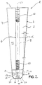
- the container 1 according to the invention is shown in a side view.
- the container 1 has a body 3 which tapers downward from a container opening 2.
- This has essentially the shape of an upside-down cone which has a flattened end region 17 at its tip, that is to say at the lower body end 8. In the illustration according to FIG. 1, this end region extends perpendicular to the plane of the figure.
- the body 3 has a smooth outer side 16, which is formed by its body wall 4.
- the body wall 4 corresponds to a lateral surface 9 of the conical body 3.
- the container opening 2 has a peripheral edge bead 22, which is formed by flanging an upper end region of the lateral surface 9.
- the container opening 2 can be closed by a removable container cover, not shown.
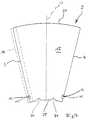
- FIG. 2 the container of Figure 1 is shown in a front view.
- the edge bead 22 is omitted from FIG. 1.
- the end region 17 at the lower body end 8 has an essentially trapezoidal cross section, two edges of the trapezoid being cut off symmetrically to the longitudinal central axis 23 by edge cutouts 20 and 21.
- an overlap area 5 is formed, which extends from the container opening 2 to the lower body end 8.
- the overlap area 5 is formed in that the lateral surface 9 is arranged to overlap in this area, a right lateral line 7 being arranged parallel to a left lateral line 6 and spaced apart therefrom on the outside 16 of the body wall 4.
- the lateral surface 9 is connected to itself.
- the overlap area 5 has on its outer side a transverse corrugation 18 which runs essentially perpendicular to the longitudinal central axis 23.
- the corrugation density of the corrugation 18 adjacent to the container opening 2 is lower than in the rest of the overlap area.
- the body 3 tapers towards the lower end 8 of the body, a taper angle ⁇ being included with a vertical parallel to the longitudinal central axis 23.
- the taper angle ⁇ is approximately 2 to 15 o .
- the overlap area 5 is interrupted in the end area 17 by a left-hand section 10 and a right-hand section 11.
- the left cutout 10 is formed in the left surface line 6 and the right cutout 11 in the right surface line 7.
- the two cutouts 10 and 11 are arranged relative to one another such that end edges 12 and 13 of the cutouts are arranged in abutment, that is to say that the end edge 13 of the right-hand cutout 11 runs parallel and directly adjacent to the right of the end edge 12 of the left-hand cutout 10.
- the overlap region 5 is continued, wherein it has a corrugation 19 which is directed parallel to the longitudinal central axis 22.
- the entire end region 17 can be provided with corrugations 18 or 19.
- the end section 27 of the right surface line 7 is arranged on the outside 16 and an end section 26 of the left surface line 6 on an inside of the body 3.
- This relative arrangement of the left and right surface lines 6 and 7 applies in the entire overlap region 5.
- the relative arrangement of the end sections 26 and 27 is reversed, that is to say the end section 26 is on the outside 16 and the end section 27 on the inside of the body.
- FIG. 3 shows a blank for the outer surface 9 of the container according to the invention.
- the lateral surface has essentially the shape of a circular ring sector.
- the lateral surface 9 is bent axially symmetrically with respect to the longitudinal central axis 23, so that the right lateral line 7 is curved over the left lateral line 6 and is placed on the outside 16 of the container according to FIG. In this way, the figure plane according to FIG. 3 becomes the inside 15 of the container 1 according to FIG. 2.
- the blank is delimited at its upper end by an upper edge 24 and at its lower end by a lower edge 25.
- the upper edge 24 surrounds the container opening 2 according to FIG. 1 or 2 and the lower edge 25 forms the lower body end 8 according to FIG. 2.
- Cutouts 10 and 11 are formed adjacent to the lower edge 25 in the left and right surface lines 6 and 7. Both cutouts are essentially rectangular, with a longer side of the rectangle forming an end edge 12 or 13. The shorter sides of the rectangle extend perpendicular to the rest of the surface line, the cutouts 10 and 11 being open opposite the end edges 12 and 13.
- the edge cutouts 20 and 21 are arranged symmetrically spaced from the longitudinal central axis 23.
- the two edge cutouts essentially have the shape of an isosceles triangle which is open towards the lower edge 25.
- the cut of the outer surface 9 is folded in the end region 17 in such a way that the legs of each edge section 20 or 21 come to lie on one another.
- a sealing and adhesive film 14 is arranged on the inside 15 of the lateral surface 9 along the left lateral line 6.
- the sealing and adhesive film 14 protrudes about half over the left surface line 6 to the outside. In the area of the left section 10, the film has a corresponding section.
- the protruding area of the sealing and adhesive film 14 is folded over onto the outside 16, see FIG. 2, and extends approximately to below the right-hand surface line 7.
- the film serves in particular for better connection of the outer surface 9 with itself in the Overlap area 5 and for better sealing of the container.
Landscapes
- Engineering & Computer Science (AREA)
- Mechanical Engineering (AREA)
- Life Sciences & Earth Sciences (AREA)
- Food Science & Technology (AREA)
- Packging For Living Organisms, Food Or Medicinal Products That Are Sensitive To Environmental Conditiond (AREA)
- Confectionery (AREA)
- Packages (AREA)
- Medicinal Preparation (AREA)
- Cosmetics (AREA)
Abstract
Description
Die Erfindung betrifft einen quetschbaren Behälter, insbesondere für Speiseeis, mit einem sich von einer Behälteröffnung nach unten verjüngenden Körper, dessen Körperwand durch eine in einem Überlappungsbereich entlang von linker und rechter Mantellinie zusammengehaltene Mantelfläche gebildet ist, welche am unteren Körperende einen flachgedrückten Endbereich aufweist.The invention relates to a squeezable container, in particular for ice cream, with a body tapering downward from a container opening, the body wall of which is formed by a lateral surface held together in an overlap region along the left and right surface lines, which has a flattened end region at the lower end of the body.
Ein solcher Behälter ist beispielsweise aus der EP 0487765 A1 bekannt. Ein in diesem Behälter enthaltenes Speiseeis, insbesondere Wassereis, wird von einem Konsumenten durch Erwärmen des Behälters mit den Händen kontinuierlich aus der Behälteröffnung herausgedrückt und verzehrt. Durch die Körperwärme bildet sich eine schmelzende Gleitschicht zwischen Körperwand und Speiseeis. Aufgrund der Behälterform ist das Speiseeis in einfacher Weise durch allmähliches Zusammenquetschen des Behälters herausdrückbar und kann bei Verringerung des Drucks auf die Körperwand in den Behälter zurückgleiten.Such a container is known for example from EP 0487765 A1. A ice cream contained in this container, in particular water ice, is continuously pressed out of the container opening and consumed by a consumer by heating the container with his hands. The body heat creates a melting sliding layer between the body wall and ice cream. Due to the shape of the container, the ice cream can be easily squeezed out by gradually squeezing the container together and can slide back into the container when the pressure on the body wall is reduced.
Während des Verzehrs des Speiseeises verflüssigt sich immer mehr mit der erwärmten Körperwand in Kontakt stehendes Speiseeis. Dieses sammelt sich am unteren Körperende oberhalb des flachgeddückten Endbereichs.During the consumption of the ice cream, more and more ice cream that is in contact with the heated body wall liquefies. This collects at the lower end of the body above the flattened end area.
Bei dem vorbekannten Behälter ist zu beachten, daß die Körperwand durch eine Mantelfläche gebildet ist, die in einem Überlappungsbereich entlang von linker und rechter Mantellinie zur Bildung des Körpers zusammengehalten ist. Das Zusammenhalten erfolgt bevorzugt durch Verkleben der sich überlappenden Abschnitte der Mantelfläche. Um in diesem Zusammenhang den Körper an einem unteren Körperende abzudichten, weist die Mantelfläche den flachgedrückten Endbereich auf, in dem der Körper vollständig zusammengedrückt ist. Der Überlappungsbereich erstreckt sich entlang des gesamten Körpers, das heißt auch im Endbereich.In the case of the known container, it should be noted that the body wall is formed by a lateral surface which is held together in an overlap region along the left and right surface lines to form the body. The holding together is preferably carried out by gluing the overlapping sections of the lateral surface. In this context, in order to seal the body at a lower end of the body, the lateral surface has the flattened end region in which the body is completely is compressed. The overlap area extends along the entire body, that is to say also in the end area.
Bei dem vorbekannten Behälter ist von Nachteil, daß bei der Herstellung des Endbereichs zum Verschließen des unteren Körperendes insbesondere im Überlappungsbereich und benachbart zu diesem ein Materialstau aufgrund der zusammengedrückten Mantelfläche auftritt. Dieser Materialstau kann dazu führen, daß der Endbereich nicht vollständig flachgedrückt und damit abgedichtet werden kann. Auf diese Weise ist der Behälter zwar bei Verzehr von Speiseeis zunächst am unteren Körperende dicht. Allerdings kann aufgrund des Zusammenquetschen des Behälters zur Entnahme des Speiseeises durch die damit verbundene Beanspruchung des Behälters das untere Körperende undicht werden. Bevorzugt dort wo bei Bildung des Endbereichs ein Materialstau aufgetreten ist. Je stärker der Behälter beim Verzehr des Speiseeises beansprucht wird, desto eher tritt eine solche Undichtigkeit auf.A disadvantage of the known container is that during the manufacture of the end region for closing the lower end of the body, in particular in the overlap region and adjacent to it, a material jam occurs due to the compressed surface area. This material jam can lead to the end area not being able to be completely flattened and thus sealed. In this way, the container is initially tight at the lower end of the body when eating ice cream. However, due to the squeezing of the container to remove the ice cream due to the associated stress on the container, the lower end of the body can leak. Preferably where a material jam occurred when the end area was formed. The more the container is used when eating the ice cream, the more likely such a leak will occur.
Der Erfindung liegt daher die Aufgabe zugrunde, ausgehend von dem vorbekannten Behälter diesen dahingehend zu verbessern, daß der Behälter auch bei fortgesetzter Beanspruchung dicht ist, wobei er gleichzeitig die Vorteile des bekannten Behälters beibehält und einfach herstellbar ist.The invention is therefore based on the object, starting from the previously known container, to improve it in such a way that the container is sealed even under continued use, while at the same time retaining the advantages of the known container and being simple to produce.
Zur Lösung dieser Aufgabe ist der Behälter mit den Merkmalen des Oberbegriffs des Anspruchs 1 im Endbereich wenigstens einer Mantellinie mit einem zur anderen Mantellinie offenen Ausschnitt ausgebildet, wobei dieser Ausschnitt zumindest teilweise im Überlappungsbereich angeordnet ist.To achieve this object, the container with the features of the preamble of
Durch die Anordnung eines solchen Ausschnittes ist die Materialstärke im Überlappungsbereich herabgesetzt, wobei gleichzeitig weggedrücktes Material zumindest teilweise vom Ausschnitt aufgenommen werden kann. Auf diese Weise ist ein Materialstau beim Flachdrücken des Endbereichs nahezu vollständig vermieden, so daß auch bei starker Beanspruchung des Behälters dessen Dichtigkeit am unteren Körperende gewährleistet ist. Gleichzeitig wird die sonstige Funktion des Behälters zum Ausdrücken des Speiseeises aus seiner Behälteröffnung in keiner Weise beeinflußt. Weiterhin wird durch die Anordnung eines Ausschnitts die Herstellung des Behälters aus einem einfachen Zuschnitt nur unwesentlich aufwendiger.The arrangement of such a cutout reduces the material thickness in the overlap area, material which has been pushed away at the same time being able to be at least partially absorbed by the cutout. In this way, a material jam when flattening the end area is almost completely avoided, so that its tightness at the lower end of the body is ensured even when the container is subjected to heavy use. At the same time, the other function of the container for squeezing the ice cream out of its container opening is in no way influenced. Furthermore, the arrangement of a cutout makes the production of the container from a simple cut only slightly more complex.
Um Materialstau darüberhinausgehend zu verhindern, erweist es sich als günstig, wenn die rechte und die linke Mantellinie wenigstens einen Rechts- beziehungsweise Linksausschnitt aufweisen. Die Ausschnitte können im Prinzip eine beliebige Form haben, wobei allerdings einfache geometrische Formen, wie Dreiecke, Vierecke, Halbkreise oder dergleichen, bevorzugt sind.In order to further prevent material jams, it proves to be advantageous if the right and left surface lines have at least one right and left cutout. In principle, the cutouts can have any shape, although simple geometric shapes such as triangles, quadrilaterals, semicircles or the like are preferred.
Bei einer anderen Ausführungsform der Erfindung kann beispielsweise nur eine Mantellinie einen Ausschnitt aufweisen, wobei die andere Mantellinie einen im wesentlichen komplementären Ansatz aufweist, der bei Herstellen des Endbereichs in den zugehörigen Ausschnitt eingepaßt wird. Auf diese Weise wird der Überlappungsbereich durch das Ineinanderpassen von Ausschnitt und Ansatz unterbrochen, wodurch bei Flachdrücken des Endbereichs entsprechend weggedrücktes Material sich im Bereich von Ausschnitt und Ansatz sammeln kann. Gleichzeitig wird durch das Flach- und Zusanmendrücken im unteren Endbereich eine sichere Abdichtung am unteren Körperende des Behälters gewährleistet.In another embodiment of the invention, for example, only one surface line can have a cutout, the other surface line having an essentially complementary approach, which is fitted into the associated cutout when the end region is produced. In this way, the overlap area is interrupted by the fit between the cutout and the neck, which means that when the end area is pressed flat, material that is pushed away can collect in the area of the neckline and neck. At the same time, the flat and compressing in the lower end area ensures a secure seal at the lower body end of the container.
Bei einer weiteren vorteilhaften Ausführungsform sind Rechts- und Linksausschnitt einander überlappend angeordnet. Der entsprechende Überlapp kann teilweise oder vollständig erfolgen.In a further advantageous embodiment, the right and left sections are arranged to overlap one another. The corresponding overlap can be partial or complete.
Um die Herstellung des erfindungsgemäßen Behälters weiterhin zu vereinfachen, sind Rechts- und Linksausschnitt bevorzugt im wesentlichen gleichförmig ausgebildet.In order to further simplify the manufacture of the container according to the invention, the right and left cutouts are preferably essentially uniform.
Um Materialstau sicher zu verhindern und gleichzeitig die Abdichtung weiter zu verbessern, ist es in diesem Zusammenhang günstig, wenn Rechts- und Linksausschnitt jeweils eine gegenüber der übrigen Mantellinie einwärts versetzte, parallele Endkante aufweisen, wobei diese Endkanten auf Stoß angeordnet sind.In order to reliably prevent material jams and at the same time further improve the seal, it is advantageous in this context if the right and left cutouts each have a parallel end edge offset inwards with respect to the rest of the surface line, these end edges being arranged in an abutting manner.
Um die Zuordnung der beiden Ausschnitte und deren Herstellung zu vereinfachen, sind Rechts- und Linksausschnitt rechteckförmig.To simplify the assignment of the two sections and their production, the right and left sections are rectangular.
Zur Herstellung des Überlappungsbereichs und des Endbereichs kann bei einem Ausführungsbeispiel die rechte Mantellinie im Überlappungsbereich außen angeordnet sein. Die linke Mantellinie ist entsprechend im Inneren des Behälters angeordnet, wobei sich die Breite des Überlappungsbereichs im wesentlichen aus dem Abstand von rechter und linker Mantellinie ergibt. Nur im Bereich der Ausschnitte sind die beiden Mantellinien beispielsweise auf Stoß entlang der Endkanten der Ausschnitte angeordnet.To produce the overlap area and the end area, the right surface line can be arranged on the outside in the overlap area in one embodiment. The left surface line is correspondingly arranged in the interior of the container, the width of the overlap region essentially resulting from the distance from the right and left surface lines. Only in the area of the cutouts are the two surface lines arranged, for example, in a butt joint along the end edges of the cutouts.
Um die Abdichtung im Endbereich weiterhin zu verbessern, ist bei einer anderen Ausführungsform der Erfindung die rechte Mantellinie im Überlappungsbereich bis zum Rechtsausschnitt außen und vom Rechtsausschnitt bis zum unteren Körperende innen angeordnet. In diesem Fall kreuzen sich die Mantellinien im Bereich der Ausschnitte, wodurch sich in diesem Bereich quasi eine Labyrinthdichtung ergibt.In order to further improve the seal in the end area, in another embodiment of the invention the right surface line is arranged in the overlap area up to the right cutout on the outside and from the right cutout to the lower body end on the inside. In this case, the surface lines intersect in the area of the cutouts, which results in a quasi-labyrinth seal in this area.
Bei beiden Ausführungsbeispielen kann unter Aufrechterhaltung der entsprechenden Vorteile die relative Anordnung der Mantellinien vertauscht werden.In both exemplary embodiments, the relative arrangement of the surface lines can be interchanged while maintaining the corresponding advantages.
Zur einfachen Herstellung des erfindungsgemäßen Behälters ist die Mantelfläche aus einem Zuschnitt in Form eines Kreisringsektors gebildet. Der Zuschnitt wird bevorzugt gleichzeitig mit den entsprechenden Ausschnitten und ansich bekannten Kantenausschnitten für den Endbereich hergestellt. Der Zuschnitt wird zur Bildung des Körpers mit seinen Mantellinien aufeinander zugebogen, wobei eine im wesentlichen kegelstumpfförmige Form entsteht. Zur Herstellung des Kegelstumpfes wird eine Mantellinie mit Abstand zur anderen Mantellinie überlappend angeordnet und die Mantelfläche im Überlappungsbereich mit sich selbst verbunden. Dabei werden die Ausschnitte im Endbereich der Mantelfläche und die bekannten Kantenausschnitte entsprechend einander zugeordnet. Schließlich wird der Kegelstumpf an seinem unteren Körperende unter Bildung des flachgedrückten Endbereichs zusammengepreßt. Dieses Zusammenpressen kann gleichzeitig mit der Verbindung der Mantelfläche im Überlappungsbereich zumindest im Endbereich oder nach bereits vollzogener Verbindung der Mantelfläche im Endbereich erfolgen. Beim Zusammenpressen wird gleichzeitig in ansich bekannter Weise die bleibende Abdichtung des Endbereichs erzeugt.For the simple manufacture of the container according to the invention, the lateral surface is formed from a blank in the form of a circular ring sector. The cut is preferably made at the same time as the corresponding cutouts and known edge cutouts made for the end area. The blank is bent towards one another with its surface lines to form the body, an essentially frustoconical shape being produced. To produce the truncated cone, a surface line is arranged to overlap at a distance from the other surface line and the surface area is connected to itself in the overlap area. The cutouts in the end region of the lateral surface and the known edge cutouts are correspondingly assigned to one another. Finally, the truncated cone is pressed together at its lower body end to form the flattened end region. This pressing together can take place simultaneously with the connection of the outer surface in the overlap region at least in the end region or after the outer surface has already been connected in the end region. When pressed together, the permanent sealing of the end region is simultaneously produced in a manner known per se.
Um in diesem Zusammenhang die Abdichtung sowohl im Überlappungsbereich als auch im Endbereich zu verbessern, ist es von Vorteil, wenn im Überlappungsbereich und/oder im Endbereich eine Dicht- und Klebefolie angeordnet ist.In this context, in order to improve the seal both in the overlap area and in the end area, it is advantageous if a sealing and adhesive film is arranged in the overlap area and / or in the end area.
Um die Klebefolie nur dort anzuwenden, wo sie gebraucht wird, ist es günstig, wenn die Dicht- und Klebefolie auf einer Innenseite entlang einer Mantellinie der Mantelfläche befestigt ist, um diese eine Mantenlinie auf die Außenseite der Mantelfläche herumgelegt ist und sich im wesentlichen bis zur anderen Mantellinie erstreckt. Wird nun der Überlappungsbereich und/oder der Endbereich gegebenenfalls unter Zufuhr von Wärme zusammengepreßt, so ergibt sich eine innige Verbindung der sich überlappenden Bereiche der Mantelfläche.In order to apply the adhesive film only where it is needed, it is advantageous if the sealing and adhesive film is fastened on an inside along a surface line of the outer surface, around which a mantle line is laid on the outer side of the outer surface and essentially up to extends another surface line. If the overlap area and / or the end area is pressed together, possibly with the addition of heat, there is an intimate connection of the overlapping areas of the lateral surface.
Zur besseren und sicheren Handhabung des Behälters ist es weiterhin von Vorteil, wenn Überlappungsbereich und/oder Endbereich auf der Außenseite eine Riffelung aufweisen. Diese kann beispielsweise beim Zusammenpressen von Überlappungsbereich und/oder Endbereich gleichzeitig hergestellt werden. Selbstverständlich kann eine entsprechende Riffelung auch an anderer Stelle auf der Außenseite des Behälters vorgesehen werden. Weiterhin ist es möglich, auf der Innenseite des Behälters Vorsprünge auszubilden, die beispielsweise einem zu schnellen Herausgleiten des Speiseeises aus dem Körper einen Gleitwiderstand entgegensetzen.For better and safer handling of the container, it is also advantageous if the overlap area and / or the end area have corrugations on the outside. This can, for example when the overlap area and / or end area are pressed together. Corresponding corrugation can of course also be provided elsewhere on the outside of the container. Furthermore, it is possible to form protrusions on the inside of the container which, for example, oppose sliding resistance of the ice cream sliding too quickly out of the body.
Zur optischen Auflockerung und um die Oberfläche des Körpers interessanter zu gestalten, kann die Riffelung abschnittsweise eine andere Ausrichtung und/oder eine andere Riffeldichte aufweisen.For optical loosening and to make the surface of the body more interesting, the corrugation can have a different orientation and / or a different corrugation density in sections.
Bevorzugt verlaufen rechte und linke Mantellinie geradlinig, wodurch die Herstellung des entsprechenden Zuschnitts vereinfacht ist. Allerdings können die Mantellinien auch zick-zack-förmig, wellenförmig oder in anderer Weise verlaufen.The right and left surface lines preferably run in a straight line, which simplifies the production of the corresponding blank. However, the surface lines can also be zigzag, wavy or in some other way.
Als Material für den Behälter wird bevorzugt ein relativ steifes aber elastisches Material verwendet, wie beispielsweise Papier oder Karton mit einer Polyäthylenbeschichtung, Papier oder Karton mit einer Aluminiumbeschichtung oder dergleichen.A relatively rigid but elastic material is preferably used as the material for the container, such as paper or cardboard with a polyethylene coating, paper or cardboard with an aluminum coating or the like.
Im folgenden werden vorteilhafte Ausführungsbeispiele der Erfindung anhand der in der Zeichnung dargestellten Figuren näher erläutert und beschrieben:Advantageous exemplary embodiments of the invention are explained and described in more detail below with reference to the figures shown in the drawing:
Es zeigen:
- Fig.1
- eine Seitenansicht eines erfindungsgemäßen Behälters;
- Fig.2
- eine Vorderansicht des erfindungsgemäßen Behälters; und
- Fig.3
- eine Draufsicht auf einen Zuschnitt für den erfindungsgemäßen Behälter.
- Fig. 1
- a side view of a container according to the invention;
- Fig. 2
- a front view of the container according to the invention; and
- Fig. 3
- a plan view of a blank for the container according to the invention.
In Figur 1 ist der erfindungsgemäße Behälter 1 in einer Seitenansicht dargestellt. Der Behälter 1 weist einen sich von einer Behälteröffnung 2 nach unten verjüngenden Körper 3 auf. Dieser hat im wesentlichen die Form eines auf dem Kopf stehenden Kegels, der an seiner Spitze, das heißt am unteren Körperende 8, einen flachgedrückten Endbereich 17 aufweist. Dieser Endbereich erstreckt sich in der Darstellung nach Figur 1 senkrecht zur Figurenebene.In Figure 1, the
Der Körper 3 weist im Prinzip eine glatte Außenseite 16 auf, die durch seine Körperwand 4 gebildet ist. Die Körperwand 4 entspricht dabei einer Mantelfläche 9 des kegelförmigen Körpers 3.In principle, the
Die Behälteröffnung 2 weist einen umlaufenden Randwulst 22 auf, der durch Umbördelung eines oberen Endbereichs der Mantelfläche 9 gebildet ist. Die Behälteröffnung 2 kann durch einen nicht dargestellten, abziehbaren Behälterdeckel verschlossen sein.The
In Figur 2 ist der Behälter aus Figur 1 in einer Vorderansicht dargestellt. Zur Vereinfachung ist der Randwulst 22 aus Figur 1 weggenlassen.In Figure 2, the container of Figure 1 is shown in a front view. For simplification, the
Gleiche Bezugszeichen kennzeichnen gleiche Bauteile und werden nur noch teilweise erwähnt.The same reference numerals designate the same components and are only mentioned in part.
In der Draufsicht nach Figur 2 weist der Endbereich 17 am unteren Körperende 8 einen im wesentlichen trapezförmigen Querschnitt auf, wobei zwei Kanten des Trapezes durch Kantenausschnitte 20 und 21 symmetrisch zur Längsmittelachse 23 abgeschnitten sind.In the plan view according to FIG. 2, the
In Richtung der Längsmittelachse 23 ist ein Überlappungsbereich 5 ausgebildet, der sich von der Behälteröffnung 2 bis zum unteren Körperende 8 erstreckt. Der Überlappungsbereich 5 ist dadurch gebildet, daß die Mantelfläche 9 in diesem Bereich überlappend angeordnet ist, wobei eine rechte Mantellinie 7 parallel zu einer linken Mantellinie 6 und beabstandet zu dieser auf der Außenseite 16 der Körperwand 4 angeordnet ist. Im Überlappungsbereich ist die Mantelfläche 9 mit sich selbst verbunden.In the direction of the longitudinal
Der Überlappungsbereich 5 weist auf seiner Außenseite eine Querriffelung 18 auf, die im wesentlichen senkrecht zur Längsmittelachse 23 verläuft. Die Riffeldichte der Riffelung 18 ist benachbart zur Behälteröffnung 2 geringer als im übrigen Überlappungsbereich.The
In der Vorderansicht nach Figur 2 verjüngt sich der Körper 3 in Richtung zum unteren Körperende 8, wobei ein Verjüngungswinkel α mit einer Vertikalen parallel zur Längsmittelachse 23 eingeschlossen wird. Der Verjüngungswinkel α beträgt in etwa 2 bis 15o.In the front view according to FIG. 2, the
Der Überlappungsbereich 5 ist im Endbereich 17 durch einen Linksausschnitt 10 und einen Rechtsausschnitt 11 unterbrochen. Der Linksausschnitt 10 ist in der linken Mantellinie 6 und der Rechtsausschnitt 11 in der rechten Mantellinie 7 ausgebildet. Die beiden Ausschnitte 10 und 11 sind relativ zueinander so angeordnet, daß Endkanten 12 und 13 der Ausschnitte auf Stoß angeordnet sind, das heißt, daß die Endkante 13 des Rechtsaussohnitts 11 parallel und direkt benachbart rechts von der Endkante 12 des Linksausschnitts 10 verläuft. Anschließend an die Ausschnitte 10 und 11 wird der Überlappungsbereich 5 fortgesetzt, wobei er eine Riffelung 19 aufweist, die parallel zur Längsmittelachse 22 gerichtet ist. In entsprechender Weise kann der gesamte Endbereich 17 mit einer Riffelung 18 beziehungsweise 19 versehen sein.The
Bei dem dargestellten Ausführungsbeispiel nach Figur 2 ist der Endabschnitt 27 der rechten Mantellinie 7 auf der Außenseite 16 und ein Endabschnitt 26 der linken Mantellinie 6 auf einer Innenseite des Körpers 3 angeordnet. Diese relative Anordnung von linker und rechter Mantellinie 6 beziehungsweise 7 gilt im gesamten Überlappungsbereich 5. Bei einem anderen Ausführungsbeispiel ist die relative Anordnung der Endabschnitte 26 und 27 umgekehrt, das heißt, der Endabschnitt 26 ist auf der Außenseite 16 und der Endabschnitt 27 auf der Innenseite des Körpers angeordnet.In the illustrated embodiment according to FIG. 2, the
In Figur 3 ist ein Zuschnitt für die Mantelfläche 9 des erfindungsgemäßen Behälters dargestellt. Die Mantelfläche weist im wesentlichen die Form eines Kreisringsektors auf. Zur Bildung des Behälters nach Figuren 1 und 2 wird die Mantelfläche 9 achsensymmetrisch zur Längsmittelachse 23 umgebogen, so daß die rechte Mantellinie 7 über die linke Mantellinie 6 gewölbt und auf der Außenseite 16 des Behälters nach Figur 2 angelegt wird. Auf diese Weise wird die Figurenebene nach Figur 3 zur Innenseite 15 des Behälters 1 nach Figur 2.FIG. 3 shows a blank for the outer surface 9 of the container according to the invention. The lateral surface has essentially the shape of a circular ring sector. To form the container according to FIGS. 1 and 2, the lateral surface 9 is bent axially symmetrically with respect to the longitudinal
Der Zuschnitt ist an seinem oberen Ende durch einen oberen Rand 24 und an seinem unteren Ende durch einen unteren Rand 25 begrenzt. Der obere Rand 24 umrandet die Behälteröffnung 2 nach Figur 1 oder 2 und der untere Rand 25 bildet das untere Körperende 8 nach Figur 2.The blank is delimited at its upper end by an
Benachbart zum unteren Rand 25 sind in der linken und der rechten Mantellinie 6 und 7 Ausschnitte 10 und 11 ausgebildet. Beide Ausschnitte sind im wesentlichen rechteckförmig, wobei eine längere Rechteckseite eine Endkante 12 beziehungsweise 13 bildet. Die kürzeren Rechteckseiten erstrecken sich senkrecht zur übrigen Mantellinie, wobei die Ausschnitte 10 und 11 gegenüberliegend zu den Endkanten 12 und 13 offen sind.
Im unteren Rand 25 sind symmetrisch beabstandet zur Längsmittelachse 23 die Kantenausschnitte 20 und 21 angeordnet. Die beiden Kantenausschnitte weisen im wesentlichen die Form eines gleichschenkligen, in Richtung zum unteren Rand 25 offenen Dreiecks auf. Entsprechend zu Figur 2 wird der Zuschnitt der Mantelfläche 9 im Endbereich 17 so zusammengefaltet, daß die Schenkel eines jeden Kantenausschnitts 20 beziehungsweise 21 aufeinander zu liegen kommen.In the
Entlang der linken Mantellinie 6 ist eine Dicht- und Klebefolie 14 auf der Innenseite 15 der Mantelfläche 9 angeordnet. Die Dicht- und Klebefolie 14 steht in etwa zur Hälfte über die linke Mantellinie 6 nach außen über. Im Bereich des Linksausschnitts 10 weist die Folie einen entsprechenden Ausschnitt auf. Beim Zusammensetzen des Behälters wird der überstehende Bereich der Dicht- und Klebefolie 14 auf die Außenseite 16, siehe Figur 2, umgelegt und erstreckt sich in etwa bis unterhalb der rechten Mantellinie 7. Die Folie dient insbesondere zur besseren Verbindung der Mantelfläche 9 mit sich selbst im Überlappungsbereich 5 und zur besseren Abdichtung des Behälters.A sealing and
Claims (14)
dadurch gekennzeichnet,
daß im Endbereich (17) in wenigstens einer Mantellinie (6, 7) ein zur anderen Mantellinie (6, 7) offener Ausschnitt (10, 11) ausgebildet ist, der zumindest teilweise im Überlappungsbereich (5) angeordnet ist.Squeezable container (1), in particular for ice cream, with a body (3) tapering downwards from a container opening (2), the body wall (4) of which through an overlap area (5) along the left and right surface lines (6, 7 ) held together lateral surface (9) is formed, which has a flattened end region (17) at the lower body end (8),
characterized,
that in the end region (17) in at least one surface line (6, 7) a cut line (6, 7) open to the other surface line (10, 11) is formed, which is at least partially arranged in the overlap region (5).
dadurch gekennzeichnet,
daß rechte und linke Mantellinie (6, 7) wenigstens einen Rechtsbeziehungsweise Linksausschnitt (10, 11) aufweisen.Crushable container according to claim 1,
characterized,
that the right and left surface lines (6, 7) have at least one right or left section (10, 11).
dadurch gekennzeichnet,
daß Rechts- und Linksausschnitt (10, 11) einander überlappend angeordnet sind.Crushable container according to claim 2,
characterized,
that the right and left sections (10, 11) are arranged to overlap each other.
dadurch gekennzeichnet,
daß Rechts- und Linksausschnitt (10, 11) im wesentlichen gleichförmig ausgebildet sind.Crushable container according to one of the preceding claims,
characterized,
that right and left cutout (10, 11) are substantially uniform.
dadurch gekennzeichnet,
daß Rechts- und Linksausschnitt (10, 11) jeweils eine gegenüber der übrigen Mantellinie (6, 7) parallel einwärts versetzte Endkante (12, 13) aufweisen, wobei diese Endkanten (12, 13) auf Stoß angeordnet sind.Crushable container according to one of the preceding claims,
characterized,
that right and left cutout (10, 11) each one opposite of the remaining surface line (6, 7) have parallel inwardly offset end edges (12, 13), these end edges (12, 13) being arranged in abutting relationship.
dadurch gekennzeichnet,
daß Rechts- und Linksausschnitt (10, 11) rechteckförmig sind.Crushable container according to one of the preceding claims,
characterized,
that right and left cutout (10, 11) are rectangular.
dadurch gekennzeichnet,
daß die rechte Mantellinie (7) im Überlappungsbereich (5) außen angeordnet ist.Crushable container according to one of the preceding claims,
characterized,
that the right surface line (7) in the overlap area (5) is arranged outside.
dadurch gekennzeichnet,
daß die rechte Mantellinie (7) im Überlappungsbereich (5) bis zum Rechtsausschnitt (11) außen und vom Rechtsausschnitt (11) bis zum unteren Körperende (8) innen angeordnet ist.Crushable container according to one of the preceding claims,
characterized,
that the right surface line (7) is arranged in the overlap area (5) to the right cutout (11) outside and from the right cutout (11) to the lower body end (8) inside.
dadurch gekennzeichnet,
daß die Mantelfläche (9) aus einem Zuschnitt in Form eines Kreisringsektors gebildet ist.Crushable container according to one of the preceding claims,
characterized,
that the outer surface (9) is formed from a blank in the form of a circular sector.
dadurch gekennzeichnet,
daß zumindestim Überlappungsbereich (5) und/oder in Endbereich (17) eine Dicht- und Klebefolie (14) angeordnet ist.Crushable container according to one of the preceding claims,
characterized,
that a sealing and adhesive film (14) is arranged at least in the overlap region (5) and / or in the end region (17).
dadurch gekennzeichnet,
daß die Dicht- und Klebefolie (14) auf einer Innenseite (15) entlang einer Mantellinie (6, 7) auf der Mantelfläche (9) befestigt ist, um die eine Mantellinie (6, 7) auf die Außenseite (16) der Mantelfläche (9) herum gelegt ist und sich bis im wesentlichen zur anderen Mantellinie (6, 7) erstreckt.Crushable container according to claim 10,
characterized,
that the sealing and adhesive film (14) is fastened on an inner side (15) along a surface line (6, 7) on the outer surface (9), around which a surface line (6, 7) on the outside (16) the lateral surface (9) is laid around and extends essentially to the other lateral line (6, 7).
dadurch gekennzeichnet,
daß der Überlappungsbereich (5) und/oder der Endbereich (17) auf der Außenseite (16) eine Riffelung (18, 19) aufweisen.Crushable container according to one of the preceding claims,
characterized,
that the overlap area (5) and / or the end area (17) on the outside (16) have a corrugation (18, 19).
dadurch gekennzeichnet,
daß die Riffelung (18, 19) abschnittsweise eine andere Ausrichtung und/oder eine andere Riffeldichte aufweist.Crushable container according to claim 12,
characterized,
that the corrugation (18, 19) has a different orientation and / or a different corrugation density in sections.
dadurch gekennzeichnet,
daß rechte und linke Mantellinie (6, 7,) geradlinig verlaufen.Crushable container according to one of the preceding claims,
characterized,
that the right and left surface lines (6, 7,) run in a straight line.
Priority Applications (7)
| Application Number | Priority Date | Filing Date | Title |
|---|---|---|---|
| DE59405257T DE59405257D1 (en) | 1994-04-12 | 1994-04-12 | Crushable container for ice cream |
| AT94105630T ATE163168T1 (en) | 1994-04-12 | 1994-04-12 | SQUEEZABLE ICE CREAM CONTAINER |
| DK94105630T DK0677457T3 (en) | 1994-04-12 | 1994-04-12 | Compressible container for ice cream |
| EP94105630A EP0677457B1 (en) | 1994-04-12 | 1994-04-12 | Sqeezable container for ice cream |
| CA002146523A CA2146523A1 (en) | 1994-04-12 | 1995-04-06 | Squeezable receptacle |
| US08/418,427 US5586689A (en) | 1994-04-12 | 1995-04-07 | Squeezable receptacle having a cut-out portion in an end section thereof |
| GR980400852T GR3026649T3 (en) | 1994-04-12 | 1998-04-15 | Sqeezable container for ice cream. |
Applications Claiming Priority (1)
| Application Number | Priority Date | Filing Date | Title |
|---|---|---|---|
| EP94105630A EP0677457B1 (en) | 1994-04-12 | 1994-04-12 | Sqeezable container for ice cream |
Publications (2)
| Publication Number | Publication Date |
|---|---|
| EP0677457A1 true EP0677457A1 (en) | 1995-10-18 |
| EP0677457B1 EP0677457B1 (en) | 1998-02-11 |
Family
ID=8215854
Family Applications (1)
| Application Number | Title | Priority Date | Filing Date |
|---|---|---|---|
| EP94105630A Expired - Lifetime EP0677457B1 (en) | 1994-04-12 | 1994-04-12 | Sqeezable container for ice cream |
Country Status (7)
| Country | Link |
|---|---|
| US (1) | US5586689A (en) |
| EP (1) | EP0677457B1 (en) |
| AT (1) | ATE163168T1 (en) |
| CA (1) | CA2146523A1 (en) |
| DE (1) | DE59405257D1 (en) |
| DK (1) | DK0677457T3 (en) |
| GR (1) | GR3026649T3 (en) |
Cited By (1)
| Publication number | Priority date | Publication date | Assignee | Title |
|---|---|---|---|---|
| DE202004007969U1 (en) * | 2004-05-18 | 2005-09-29 | Seda S.P.A., Arzano | container |
Families Citing this family (11)
| Publication number | Priority date | Publication date | Assignee | Title |
|---|---|---|---|---|
| USD418747S (en) * | 1999-04-08 | 2000-01-11 | Recot, Inc. | Flexible package for snack foods or the like |
| US6179165B1 (en) * | 1999-06-23 | 2001-01-30 | David Knight | Pastry bag construction |
| ES2218361T3 (en) | 2001-01-30 | 2004-11-16 | Seda S.P.A. | CARTON PACK FOR DRINKS AND ITS PROCEDURE. |
| US20070110871A1 (en) * | 2003-10-02 | 2007-05-17 | Campina B.V. | Ice cream having improved stability |
| DE20319691U1 (en) * | 2003-12-18 | 2005-05-04 | Seda S.P.A., Arzano | Blank for a container and container made from the blank |
| US20060157544A1 (en) * | 2005-01-18 | 2006-07-20 | Norse Dairy Systems, Llc | Cone sleeve |
| BRPI0601188B1 (en) | 2005-04-15 | 2018-06-26 | Seda S.P.A. | ISOLATED CONTAINER; METHOD OF MANUFACTURING THE SAME AND APPARATUS FOR MANUFACTURING |
| DE202005014177U1 (en) | 2005-09-08 | 2005-11-17 | Seda S.P.A., Arzano | Double-walled beaker comprises an inner wall formed by an inner beaker which is made of a fluid-tight plastic material, and is releasably inserted into an outer beaker forming the outer wall |
| SI1785370T2 (en) | 2005-11-11 | 2014-05-30 | Seda S.P.A. | Insulated cup |
| EP1785265A1 (en) * | 2005-11-14 | 2007-05-16 | SEDA S.p.A. | Device for producing a stacking projection on a container wall and container with same |
| DE202006018406U1 (en) | 2006-12-05 | 2008-04-10 | Seda S.P.A. | packaging |
Citations (3)
| Publication number | Priority date | Publication date | Assignee | Title |
|---|---|---|---|---|
| FR570370A (en) * | 1924-04-29 | |||
| US1741490A (en) * | 1927-11-02 | 1929-12-31 | Edward C Angell | Paper container |
| EP0487765A1 (en) * | 1990-11-27 | 1992-06-03 | SEDA S.p.A. | Squeezable container for ice-cream |
Family Cites Families (4)
| Publication number | Priority date | Publication date | Assignee | Title |
|---|---|---|---|---|
| US1294011A (en) * | 1917-10-16 | 1919-02-11 | Arthur F Williams | Container. |
| US2147349A (en) * | 1934-11-14 | 1939-02-14 | Piquerez Emile | Packing or wrapping for viscous liquids and pasty materials |
| IT1209654B (en) * | 1985-08-01 | 1989-08-30 | Conti Spa | CONTAINER PARTICULARLY FOR DENSE, SEMI-DENSE AND SIMILAR FOOD PRODUCTS. |
| US4813862A (en) * | 1986-09-09 | 1989-03-21 | Bowers Paul K | Dispenser package for extrudable comestibles |
-
1994
- 1994-04-12 DE DE59405257T patent/DE59405257D1/en not_active Expired - Fee Related
- 1994-04-12 DK DK94105630T patent/DK0677457T3/en active
- 1994-04-12 EP EP94105630A patent/EP0677457B1/en not_active Expired - Lifetime
- 1994-04-12 AT AT94105630T patent/ATE163168T1/en not_active IP Right Cessation
-
1995
- 1995-04-06 CA CA002146523A patent/CA2146523A1/en not_active Abandoned
- 1995-04-07 US US08/418,427 patent/US5586689A/en not_active Expired - Fee Related
-
1998
- 1998-04-15 GR GR980400852T patent/GR3026649T3/en unknown
Patent Citations (3)
| Publication number | Priority date | Publication date | Assignee | Title |
|---|---|---|---|---|
| FR570370A (en) * | 1924-04-29 | |||
| US1741490A (en) * | 1927-11-02 | 1929-12-31 | Edward C Angell | Paper container |
| EP0487765A1 (en) * | 1990-11-27 | 1992-06-03 | SEDA S.p.A. | Squeezable container for ice-cream |
Cited By (1)
| Publication number | Priority date | Publication date | Assignee | Title |
|---|---|---|---|---|
| DE202004007969U1 (en) * | 2004-05-18 | 2005-09-29 | Seda S.P.A., Arzano | container |
Also Published As
| Publication number | Publication date |
|---|---|
| DE59405257D1 (en) | 1998-03-19 |
| ATE163168T1 (en) | 1998-02-15 |
| EP0677457B1 (en) | 1998-02-11 |
| US5586689A (en) | 1996-12-24 |
| CA2146523A1 (en) | 1995-10-13 |
| DK0677457T3 (en) | 1998-09-23 |
| GR3026649T3 (en) | 1998-07-31 |
Similar Documents
| Publication | Publication Date | Title |
|---|---|---|
| DE69508986T2 (en) | Process for the production of a hose pack and pack produced by this process | |
| DE3422546C2 (en) | Container cap | |
| DE2359531C2 (en) | Safety cap for an aerosol container | |
| DE4011071A1 (en) | PACK | |
| EP0677457B1 (en) | Sqeezable container for ice cream | |
| WO1999065791A1 (en) | Dimensionally stable plastic welding part | |
| WO2009015634A1 (en) | Device for opening and closing a beverage container | |
| DE69000976T2 (en) | PACKAGING. | |
| WO1999039984A1 (en) | Reclosable pouring element and a flat gable composite packaging provided therewith | |
| WO2019174809A1 (en) | Valve arrangement and discharge device | |
| DE2649721B2 (en) | Container and method and apparatus for the manufacture thereof | |
| EP0144736B1 (en) | Package for liquids | |
| DE69901521T2 (en) | Heater for heat sealing container bottom parts | |
| DE2428355B2 (en) | Process for filling and closing packaging containers and containers manufactured by the process | |
| CH635792A5 (en) | Squeezable delivery container | |
| DE2659521A1 (en) | CONTAINER AND METHOD FOR ITS MANUFACTURING | |
| CH680358A5 (en) | Pourer for thermoplastic material packaging with pouring throat - has two arms extending at angle from throat and formed by through central web from which seal ribs extend on both sides | |
| DE4429057A1 (en) | Stackable lid for container | |
| DE2825837B2 (en) | Container molded from plastic film | |
| DE4009397A1 (en) | CAN-LIKE PACKAGING FOR FLOWABLE PRODUCTS | |
| EP0731036B1 (en) | Lid | |
| DE4432718A1 (en) | Plastic package with tear-off strap and mfg. tool | |
| EP2091829A1 (en) | Fluid container | |
| DE2900625A1 (en) | METHOD OF MANUFACTURING A CARTON PACK AND CARTON PACK PRODUCED THEREFORE | |
| CH453117A (en) | Can closure |
Legal Events
| Date | Code | Title | Description |
|---|---|---|---|
| PUAI | Public reference made under article 153(3) epc to a published international application that has entered the european phase |
Free format text: ORIGINAL CODE: 0009012 |
|
| AK | Designated contracting states |
Kind code of ref document: A1 Designated state(s): AT BE CH DE DK ES FR GB GR IE IT LI LU MC NL PT SE |
|
| 17P | Request for examination filed |
Effective date: 19960226 |
|
| GRAG | Despatch of communication of intention to grant |
Free format text: ORIGINAL CODE: EPIDOS AGRA |
|
| 17Q | First examination report despatched |
Effective date: 19970122 |
|
| GRAG | Despatch of communication of intention to grant |
Free format text: ORIGINAL CODE: EPIDOS AGRA |
|
| GRAH | Despatch of communication of intention to grant a patent |
Free format text: ORIGINAL CODE: EPIDOS IGRA |
|
| GRAH | Despatch of communication of intention to grant a patent |
Free format text: ORIGINAL CODE: EPIDOS IGRA |
|
| GRAA | (expected) grant |
Free format text: ORIGINAL CODE: 0009210 |
|
| AK | Designated contracting states |
Kind code of ref document: B1 Designated state(s): AT BE CH DE DK ES FR GB GR IE IT LI LU MC NL PT SE |
|
| PG25 | Lapsed in a contracting state [announced via postgrant information from national office to epo] |
Ref country code: NL Free format text: LAPSE BECAUSE OF FAILURE TO SUBMIT A TRANSLATION OF THE DESCRIPTION OR TO PAY THE FEE WITHIN THE PRESCRIBED TIME-LIMIT Effective date: 19980211 Ref country code: GR Free format text: LAPSE BECAUSE OF FAILURE TO SUBMIT A TRANSLATION OF THE DESCRIPTION OR TO PAY THE FEE WITHIN THE PRESCRIBED TIME-LIMIT Effective date: 19980211 Ref country code: FR Free format text: THE PATENT HAS BEEN ANNULLED BY A DECISION OF A NATIONAL AUTHORITY Effective date: 19980211 Ref country code: ES Free format text: THE PATENT HAS BEEN ANNULLED BY A DECISION OF A NATIONAL AUTHORITY Effective date: 19980211 |
|
| REF | Corresponds to: |
Ref document number: 163168 Country of ref document: AT Date of ref document: 19980215 Kind code of ref document: T |
|
| REG | Reference to a national code |
Ref country code: CH Ref legal event code: EP |
|
| REF | Corresponds to: |
Ref document number: 59405257 Country of ref document: DE Date of ref document: 19980319 |
|
| PG25 | Lapsed in a contracting state [announced via postgrant information from national office to epo] |
Ref country code: LU Free format text: LAPSE BECAUSE OF NON-PAYMENT OF DUE FEES Effective date: 19980412 Ref country code: IE Free format text: LAPSE BECAUSE OF NON-PAYMENT OF DUE FEES Effective date: 19980412 Ref country code: AT Free format text: LAPSE BECAUSE OF NON-PAYMENT OF DUE FEES Effective date: 19980412 |
|
| PG25 | Lapsed in a contracting state [announced via postgrant information from national office to epo] |
Ref country code: SE Free format text: LAPSE BECAUSE OF NON-PAYMENT OF DUE FEES Effective date: 19980413 |
|
| ITF | It: translation for a ep patent filed | ||
| ET | Fr: translation filed | ||
| PG25 | Lapsed in a contracting state [announced via postgrant information from national office to epo] |
Ref country code: LI Free format text: LAPSE BECAUSE OF NON-PAYMENT OF DUE FEES Effective date: 19980430 Ref country code: DK Free format text: LAPSE BECAUSE OF NON-PAYMENT OF DUE FEES Effective date: 19980430 Ref country code: CH Free format text: LAPSE BECAUSE OF NON-PAYMENT OF DUE FEES Effective date: 19980430 Ref country code: BE Free format text: LAPSE BECAUSE OF NON-PAYMENT OF DUE FEES Effective date: 19980430 |
|
| PG25 | Lapsed in a contracting state [announced via postgrant information from national office to epo] |
Ref country code: GB Free format text: LAPSE BECAUSE OF NON-PAYMENT OF DUE FEES Effective date: 19980511 |
|
| GBT | Gb: translation of ep patent filed (gb section 77(6)(a)/1977) |
Effective date: 19980417 |
|
| NLV1 | Nl: lapsed or annulled due to failure to fulfill the requirements of art. 29p and 29m of the patents act | ||
| REG | Reference to a national code |
Ref country code: IE Ref legal event code: FG4D Free format text: 78882 |
|
| REG | Reference to a national code |
Ref country code: PT Ref legal event code: SC4A Free format text: AVAILABILITY OF NATIONAL TRANSLATION Effective date: 19980417 |
|
| REG | Reference to a national code |
Ref country code: DK Ref legal event code: T3 |
|
| BERE | Be: lapsed |
Owner name: SEDA S.P.A. Effective date: 19980430 |
|
| PG25 | Lapsed in a contracting state [announced via postgrant information from national office to epo] |
Ref country code: MC Free format text: LAPSE BECAUSE OF NON-PAYMENT OF DUE FEES Effective date: 19981031 |
|
| REG | Reference to a national code |
Ref country code: CH Ref legal event code: PL |
|
| PLBE | No opposition filed within time limit |
Free format text: ORIGINAL CODE: 0009261 |
|
| STAA | Information on the status of an ep patent application or granted ep patent |
Free format text: STATUS: NO OPPOSITION FILED WITHIN TIME LIMIT |
|
| GBPC | Gb: european patent ceased through non-payment of renewal fee |
Effective date: 19980511 |
|
| EUG | Se: european patent has lapsed |
Ref document number: 94105630.1 |
|
| PG25 | Lapsed in a contracting state [announced via postgrant information from national office to epo] |
Ref country code: DE Free format text: LAPSE BECAUSE OF NON-PAYMENT OF DUE FEES Effective date: 19990202 |
|
| 26N | No opposition filed | ||
| REG | Reference to a national code |
Ref country code: FR Ref legal event code: ST |
|
| PG25 | Lapsed in a contracting state [announced via postgrant information from national office to epo] |
Ref country code: PT Free format text: LAPSE BECAUSE OF NON-PAYMENT OF DUE FEES Effective date: 19991031 |
|
| REG | Reference to a national code |
Ref country code: PT Ref legal event code: MM4A Free format text: LAPSE DUE TO NON-PAYMENT OF FEES Effective date: 19991031 |
|
| REG | Reference to a national code |
Ref country code: DK Ref legal event code: EBP |
|
| PG25 | Lapsed in a contracting state [announced via postgrant information from national office to epo] |
Ref country code: IT Free format text: LAPSE BECAUSE OF NON-PAYMENT OF DUE FEES;WARNING: LAPSES OF ITALIAN PATENTS WITH EFFECTIVE DATE BEFORE 2007 MAY HAVE OCCURRED AT ANY TIME BEFORE 2007. THE CORRECT EFFECTIVE DATE MAY BE DIFFERENT FROM THE ONE RECORDED. Effective date: 20050412 |
|
| PG25 | Lapsed in a contracting state [announced via postgrant information from national office to epo] |
Ref country code: PT Free format text: LAPSE BECAUSE OF NON-PAYMENT OF DUE FEES Effective date: 19980412 |