EP0676629A2 - Refractive index measurement of spectacle lenses - Google Patents
Refractive index measurement of spectacle lenses Download PDFInfo
- Publication number
- EP0676629A2 EP0676629A2 EP95104527A EP95104527A EP0676629A2 EP 0676629 A2 EP0676629 A2 EP 0676629A2 EP 95104527 A EP95104527 A EP 95104527A EP 95104527 A EP95104527 A EP 95104527A EP 0676629 A2 EP0676629 A2 EP 0676629A2
- Authority
- EP
- European Patent Office
- Prior art keywords
- response
- reflecting
- sample
- translatable
- reference beam
- Prior art date
- Legal status (The legal status is an assumption and is not a legal conclusion. Google has not performed a legal analysis and makes no representation as to the accuracy of the status listed.)
- Granted
Links
Images
Classifications
-
- G—PHYSICS
- G01—MEASURING; TESTING
- G01M—TESTING STATIC OR DYNAMIC BALANCE OF MACHINES OR STRUCTURES; TESTING OF STRUCTURES OR APPARATUS, NOT OTHERWISE PROVIDED FOR
- G01M11/00—Testing of optical apparatus; Testing structures by optical methods not otherwise provided for
- G01M11/02—Testing optical properties
- G01M11/0228—Testing optical properties by measuring refractive power
-
- G—PHYSICS
- G01—MEASURING; TESTING
- G01B—MEASURING LENGTH, THICKNESS OR SIMILAR LINEAR DIMENSIONS; MEASURING ANGLES; MEASURING AREAS; MEASURING IRREGULARITIES OF SURFACES OR CONTOURS
- G01B9/00—Measuring instruments characterised by the use of optical techniques
- G01B9/02—Interferometers
- G01B9/02001—Interferometers characterised by controlling or generating intrinsic radiation properties
- G01B9/02002—Interferometers characterised by controlling or generating intrinsic radiation properties using two or more frequencies
-
- G—PHYSICS
- G01—MEASURING; TESTING
- G01B—MEASURING LENGTH, THICKNESS OR SIMILAR LINEAR DIMENSIONS; MEASURING ANGLES; MEASURING AREAS; MEASURING IRREGULARITIES OF SURFACES OR CONTOURS
- G01B9/00—Measuring instruments characterised by the use of optical techniques
- G01B9/02—Interferometers
- G01B9/02015—Interferometers characterised by the beam path configuration
- G01B9/02024—Measuring in transmission, i.e. light traverses the object
-
- G—PHYSICS
- G01—MEASURING; TESTING
- G01B—MEASURING LENGTH, THICKNESS OR SIMILAR LINEAR DIMENSIONS; MEASURING ANGLES; MEASURING AREAS; MEASURING IRREGULARITIES OF SURFACES OR CONTOURS
- G01B9/00—Measuring instruments characterised by the use of optical techniques
- G01B9/02—Interferometers
- G01B9/0209—Low-coherence interferometers
-
- G—PHYSICS
- G01—MEASURING; TESTING
- G01B—MEASURING LENGTH, THICKNESS OR SIMILAR LINEAR DIMENSIONS; MEASURING ANGLES; MEASURING AREAS; MEASURING IRREGULARITIES OF SURFACES OR CONTOURS
- G01B2290/00—Aspects of interferometers not specifically covered by any group under G01B9/02
- G01B2290/15—Cat eye, i.e. reflection always parallel to incoming beam
Definitions
- the present invention pertains to method and apparatus for measuring a refractive index of spectacle lenses.
- Another method utilized to measure the index of refraction of glass entails measuring the reflectivity of glass, which reflectivity depends on the index of refraction.
- the relation between index of refraction and reflectivity is described, for example, by the Fresnel formula shown on p. 75 of the above-identified reference.
- Yet another method utilized to measure the index of refraction of glass entails measuring the deflection angle of a light beam passing through a sample block of glass. This method is illustrated on pp. 62-63 of the above-identified reference.
- All of the above methods suffer from drawbacks.
- all of the above methods require the surface geometry of the glass whose index of refraction is to be measured to be known.
- the radii of curvature of the surfaces must be measured to an accuracy of about 0.1% to obtain a measurement of index of refraction of comparable accuracy.
- the first two methods are measurements of reflection. This is a drawback when measuring the index of refraction of spectacles since spectacles are often antireflection coated.
- Embodiments of the present invention advantageously satisfy the above-identified need in the art and provide a method and apparatus for measuring the index of refraction of glass such as the glass of spectacle lenses without measuring the surface geometry of the glass.
- a first embodiment of the present invention is apparatus for measuring the index of refraction of a material which comprises: (a) a source of a substantially spatially coherent beam of radiation; (b) means, in response to the beam, for providing a sample beam and a reference beam; (c) translatable reflecting means, disposed to reflect the reference beam; (d) holding means for holding the material in the path of the sample beam, said holding means comprising reflecting means for reflecting the sample beam back through the material and means for determining the thickness of the material where the sample beam passes through; (d) detector means, disposed to detect the reflected reference beam and the reflected sample beam, for producing a detector output signal in response thereto; and (f) analysis means, in response to the detector output signal, for determining a position of the translatable reflecting means and, in response to the position of the translatable reflecting means and the thickness of the material, for determining the index of refraction of the material.
- the source is an light emitting diode whose output is collimated and focused through a pinhole;
- the means for providing a sample and a reference beam is a beamsplitter;
- the translatable reflecting means is a retroreflector mounted on a stepper motor;
- the holder for the material is a caliper which holds the material at a predetermined distance from the beamsplitter and a retroreflector;
- the detector means comprises a detector whose output is bandpass filtered, root means square filtered, and applied to a trigger.
- a second embodiment of the present invention is apparatus for measuring the index of refraction of a material which comprises: (a) a source of a substantially spatially coherent beam of radiation; (b) means, in response to the beam, for providing a sample beam and a first and a second reference beam; (c) translatable reflecting means, disposed to reflect the first reference beam; (d) holding means for holding the material in the path of the sample beam, said holding means comprising reflecting means for reflecting the sample beam back through the material and means for reflecting the second reference beam; (e) detector means, disposed to detect the reflected first reference beam, the reflected second reference beam, and the reflected sample beam, for producing a detector output signal in response thereto; and (f) analysis means, in response to the detector output signal, for determining a first and a second position of the translatable reflecting means and means, in response to the first and second positions of the translatable reflecting means, for determining the index of refraction of the material.
- the source is an light emitting diode whose output is collimated and focused through a pinhole;
- the means for providing a sample and a first and second reference beam is a first and a second beamsplitter;
- the translatable reflecting means is a retroreflector mounted on a stepper motor;
- the holder for the material is a caliper which holds the material and a first and a second retroreflector;
- the detector means comprises a detector whose output is bandpass filtered, root means square filtered, and applied to a trigger.
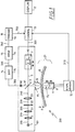
- FIG. 1 shows, in pictorial form, embodiment 200 of the present invention which is apparatus for measuring the index of refraction of glass such as the glass of spectacle lens 8 without measuring the curvature of the surface of the glass.
- a beam of light 205 output by light source 1 is collimated as beam 210 by collimator lens 2.
- output 205 from light source 1 has a short coherence length, which coherence length is preferably on the order of a few microns.
- a suitable light source may be, for example, a light emitting diode ("LED").
- beam 230 output from pinhole 22 is spatially coherent.
- beam 230 may be provided as the output from a superluminescent light source such as a superluminescent diode.
- a superluminescent diode is a diffraction limited source, it requires more critical alignment than does the extended LED source arrangement shown in FIG. 1.
- Beam 230 is again collimated, this time by collimator lens 23, into beam 240.
- Beam 240 impinges upon beamsplitter 3 to form sample beam 4 and reference beam 5.
- reference beam 5 is directed to impinge upon reference mirror 6 which is mounted on movable stage 7.
- Reference mirror 6 can be, for example, a retroreflector such as a retroreflecting prism.
- sample beam 4 is directed to impinge upon spectacle lens 8 at its vertex point.
- Sample beam 4 passes through spectacle lens 8 and impinges upon retroreflecting prism 9 which is mounted on a movable arm of caliper 27.
- Retroreflected sample beam 4 and retroreflected reference beam 5 are superimposed in detector path 91 and the combined signal is detected by light detector 92.
- reference mirror 6 is moved back and forth by movable stage 7 at a constant linear speed v.
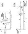
- FIG. 2 shows, in graphical form, detector signal 300 produced by detector 92.
- vertical axis 400 represents the amplitude of detector signal 300 and horizontal axis 410 represents the displacement of reference mirror 7.
- the signal length is about equal to the coherence length of light source 1 and, in an embodiment where light source 1 is an LED, the signal length is on the order of microns.
- n the index of refraction of spectacle lens 8 is determined by solving eqn. 3 for n; this is done in accordance with the embodiment as described below.
- Part of the setup steps in carrying out the inventive method entails measuring thickness d of spectacle lens 8.
- Caliper 27 having pins 10 and 11 is utilized for this purpose.
- retroreflector 9 is fixed to movable pin 11 of caliper 27 and pin 10 of caliper 27 is fixed to interferometer platform 101.
- the use of a fixed distance between pin 11 and retroreflector 9 and a fixed distance between pin 10 and interferometer platform 101 provides d1 and d2 of eqn. 3 as known, predetermined values.
- the thickness d of spectacle lens 8 is measured by displacement sensor 12.
- Displacement sensor 12 measures the displacement of pin 11 of caliper 27 which holds retroreflector 9.
- Electrical readout signal 310 from displacement sensor 12 is transmitted to control unit 13 which outputs signal 320 to drive stepper motor 7.
- signal 300 from detector 92 is bandpass filtered by bandpass filter 14.
- Output signal 330 from bandpass filter 14 is an oscillating signal pulse with a frequency given by eqn. (2) and a pulse length which corresponds to the coherence length of light source 1.
- Output 330 from bandpass filter 14 is further filtered by root mean square filter 15 to obtain the envelope of the signal pulse produced by detector 92, i.e., signal 340.
- output signal 340 from root mean filter 15 is applied as input to trigger unit 16, for example, a Schmitt trigger, to derive timing signal 350 from signal pulse 340.
- Timing pulse 350 is applied as input to control unit 13.
- control unit 13 in response to timing signal 350 from trigger 16, stores the position of stepper motor 7 at the moment of trigger pulse 350.
- the position of stepper motor 7 corresponds to the reference arm length which is equal to the optical path length of sample beam 4. This optical length is equal to L of eqn. 2 above.
- control unit 13 has the values needed to solve eqn. 3 for the index of refraction n: (a) d1 and d2 (as discussed above, d1 and d2 are obtained as predetermined values); (b) d (as discussed-above, d is obtained from signal 310 output by displacement sensor 12); and (c) L (as discussed above, L is obtained from the position of stepper motor 7).
- Control unit 13 solves eqn. 3 for n, the index of refraction of the material of spectacle lens 8, and displays the value, for example, on display 17.
- Many methods and apparatus should be well known to those of ordinary skill in the art for providing control unit 13.
- control unit 13 may be fabricated utilizing readily available microprocessor apparatus.
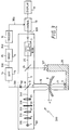
- FIG. 3 shows, in pictorial form, alternate embodiment 500 of the present invention which is apparatus for measuring the index of refraction of glass such as the glass of spectacle lens 8 without measuring the curvature of the surface of the glass.
- beam 240 is a spatially coherent, collimated beam which is divided by beamsplitter 3 into sample beam 4 and reference beam 5.
- reference beam 5 is further split by beamsplitter 24 into a first reference beam 25 and a second reference beam 26.
- First reference beam 25 is reflected by reference retroreflector 6 which is mounted on stepper motor driven, movable stage 7.
- Second reference beam 26 is reflected by retroreflector 127 which is mounted on platform 28. As shown in FIG. 3, retroreflector 9 and caliper pin 11 are also mounted on platform 28. Backreflected, second reference beam 26 is reflected by beamsplitter 24 and beamsplitter 3 and, finally, is superposed with backreflected, first reference beam 25 and backreflected, sample beam 4 in detector beam path 91.
- the inventive measurement process takes place as follows. Spectacle lens 8 is brought between caliper pins 10 and 11 so that they are in close contact with spectacle lens 8.
- the geometrical path between beamsplitter 3, beamsplitter 24 and retroreflector 127 is chosen to be the same as the geometrical path between beamsplitter 3 and retroreflector 9.
- retroreflector 6 is moved back and forth by movable stage 7 at a constant liner speed v and detector 92 produces detector signal 600 shown in FIG. 4.
- vertical axis 610 represents the amplitude of detector signal 600 and horizontal axis 620 represents the displacement of reference mirror 7.
- the position of signal peak 1001 in FIG. 4 marks the position of retroreflector 127 relative to a zero point of caliper 27, i.e., the zero point of caliper 27 corresponds to a point where caliper pins 10 and 11 in FIG. 3 are in contact (no spectacle 8).
- the position of peak 1001 in FIG. 4 measures the thickness d of spectacle lens 8.
- the position of signal peak 2001 in FIG. 4 depends on the optical thickness nd of spectacle lens 8. Peaks 1001 and 2001 are determined by control 13 from signal 350 output from trigger 16 as described above in connection with FIG. 1.
- control 13 uses peaks 1001 and 2001 to obtain the position of retroreflector 6 and, thereby, d and nd. Using these two numbers, d and nd, control 13 solves for n and displays the result on display 17.
- Alternative embodiment 500 shown in FIG. 3 is advantageous in that there is no need for displacement sensor 12 shown in FIG. 1 and there is no need to know d1 (the distance from the upper surface of spectacle lens 8 to beamsplitter 3) or d2 (the distance from the lower surface of spectacle lens 8 to retroreflector 9).
- signal 300 from detector 92 is bandpass filtered by bandpass filter 14.
- Output signal 330 from bandpass filter 14 is two oscillating signal pulses, each with a frequency given by eqn. (2) and a pulse length which corresponds to the coherence length of light source 1.
- Output 330 from bandpass filter 14 is further filtered by root mean square filter 15 to obtain the envelope of the signal pulse produced by detector 92, i.e., signal 340.
- output signal 340 from root mean filter 15 is applied as input to trigger unit 16, for example, a Schmitt trigger, to derive timing signal 350 from signal pulse 340.
- Timing pulse 350 is applied as input to control unit 13.
- control unit 13 in response to timing signal 350 from trigger 16, stores the position of stepper motor 7 at the moment of each of the pulses in timing pulse 350. As set forth above, the position of stepper motor 7 corresponding to peak 1001 produces d and the position of stepper motor 7 corresponding to peak 2001 produces nd.
Landscapes
- Physics & Mathematics (AREA)
- General Physics & Mathematics (AREA)
- Chemical & Material Sciences (AREA)
- Analytical Chemistry (AREA)
- Investigating Or Analysing Materials By Optical Means (AREA)
- Length Measuring Devices By Optical Means (AREA)
- Testing Of Optical Devices Or Fibers (AREA)
Abstract
Description
- The present invention pertains to method and apparatus for measuring a refractive index of spectacle lenses.
- There are various methods in the prior art which are used to measure the index of refraction of glass. One method entails utilizing an Abbe refractometer to measure the critical angle of total reflection. In accordance with this method, the index of refraction is derived from the measured value of the critical angle. This method is illustrated in a book entitled "Optics" by Eugene Hecht and Alfred Zajac, published by Addison-Wesley Publishing Company, Inc. February, 1979 (Copyright 1974), pp. 81-84.
- Another method utilized to measure the index of refraction of glass entails measuring the reflectivity of glass, which reflectivity depends on the index of refraction. The relation between index of refraction and reflectivity is described, for example, by the Fresnel formula shown on p. 75 of the above-identified reference.
- Yet another method utilized to measure the index of refraction of glass entails measuring the deflection angle of a light beam passing through a sample block of glass. This method is illustrated on pp. 62-63 of the above-identified reference.
- All of the above methods suffer from drawbacks. For example, all of the above methods require the surface geometry of the glass whose index of refraction is to be measured to be known. For example, the radii of curvature of the surfaces must be measured to an accuracy of about 0.1% to obtain a measurement of index of refraction of comparable accuracy. In addition, the first two methods are measurements of reflection. This is a drawback when measuring the index of refraction of spectacles since spectacles are often antireflection coated.
- In light of the above, there is a need for a method and apparatus for measuring the index of refraction of glass such as the glass of spectacle lenses without measuring the surface geometry of the glass.
- Embodiments of the present invention advantageously satisfy the above-identified need in the art and provide a method and apparatus for measuring the index of refraction of glass such as the glass of spectacle lenses without measuring the surface geometry of the glass.
- In particular, a first embodiment of the present invention is apparatus for measuring the index of refraction of a material which comprises: (a) a source of a substantially spatially coherent beam of radiation; (b) means, in response to the beam, for providing a sample beam and a reference beam; (c) translatable reflecting means, disposed to reflect the reference beam; (d) holding means for holding the material in the path of the sample beam, said holding means comprising reflecting means for reflecting the sample beam back through the material and means for determining the thickness of the material where the sample beam passes through; (d) detector means, disposed to detect the reflected reference beam and the reflected sample beam, for producing a detector output signal in response thereto; and (f) analysis means, in response to the detector output signal, for determining a position of the translatable reflecting means and, in response to the position of the translatable reflecting means and the thickness of the material, for determining the index of refraction of the material.
- In a specific instance of the first embodiment of the present invention, the source is an light emitting diode whose output is collimated and focused through a pinhole; the means for providing a sample and a reference beam is a beamsplitter; the translatable reflecting means is a retroreflector mounted on a stepper motor; the holder for the material is a caliper which holds the material at a predetermined distance from the beamsplitter and a retroreflector; and the detector means comprises a detector whose output is bandpass filtered, root means square filtered, and applied to a trigger.
- In particular, a second embodiment of the present invention is apparatus for measuring the index of refraction of a material which comprises: (a) a source of a substantially spatially coherent beam of radiation; (b) means, in response to the beam, for providing a sample beam and a first and a second reference beam; (c) translatable reflecting means, disposed to reflect the first reference beam; (d) holding means for holding the material in the path of the sample beam, said holding means comprising reflecting means for reflecting the sample beam back through the material and means for reflecting the second reference beam; (e) detector means, disposed to detect the reflected first reference beam, the reflected second reference beam, and the reflected sample beam, for producing a detector output signal in response thereto; and (f) analysis means, in response to the detector output signal, for determining a first and a second position of the translatable reflecting means and means, in response to the first and second positions of the translatable reflecting means, for determining the index of refraction of the material.
- In a specific instance of the second embodiment of the present invention, the source is an light emitting diode whose output is collimated and focused through a pinhole; the means for providing a sample and a first and second reference beam is a first and a second beamsplitter; the translatable reflecting means is a retroreflector mounted on a stepper motor; the holder for the material is a caliper which holds the material and a first and a second retroreflector; and the detector means comprises a detector whose output is bandpass filtered, root means square filtered, and applied to a trigger.
- A complete understanding of the present invention may be gained by considering the following detailed description together with the accompanying drawings, in which:
- FIG. 1 shows, in pictorial form, a preferred embodiment of the present invention which is apparatus for measuring the index of refraction of glass such as the glass of spectacle lenses without measuring the curvature of the surface of the glass;
- FIG. 2 shows, in graphical form, a signal produced by a detector in accordance with the present invention;
- FIG. 3 shows, in pictorial form, an alternate embodiment of the present invention; and
- FIG. 4, shows, in graphical form, a signal produced by a detector in accordance with the alternative embodiment of the present invention.
- Corresponding elements in each of the drawings have the same reference numbers.
- FIG. 1 shows, in pictorial form,
embodiment 200 of the present invention which is apparatus for measuring the index of refraction of glass such as the glass ofspectacle lens 8 without measuring the curvature of the surface of the glass. - In the embodiment of the present invention shown in FIG. 1, a beam of
light 205 output bylight source 1 is collimated asbeam 210 by collimator lens 2. In accordance with the present invention,output 205 fromlight source 1 has a short coherence length, which coherence length is preferably on the order of a few microns. A suitable light source may be, for example, a light emitting diode ("LED"). - Collimated
output 210 from lens 2 is focused bylens 21 having focal length f asbeam 220 ontosmall pinhole 22 having a diameter substantially given by the following formula:
LED 1 and a is the radius of collimatedbeam 210 formed by lens 2. The result is thatbeam 230 output frompinhole 22 is spatially coherent. In other embodiments,beam 230 may be provided as the output from a superluminescent light source such as a superluminescent diode. Although a superluminescent diode is a diffraction limited source, it requires more critical alignment than does the extended LED source arrangement shown in FIG. 1. - Beam 230 is again collimated, this time by
collimator lens 23, intobeam 240. Beam 240 impinges uponbeamsplitter 3 to formsample beam 4 andreference beam 5. - As shown in FIG. 1,
reference beam 5 is directed to impinge uponreference mirror 6 which is mounted on movable stage 7.Reference mirror 6 can be, for example, a retroreflector such as a retroreflecting prism. - As further shown in FIG. 1,
sample beam 4 is directed to impinge uponspectacle lens 8 at its vertex point.Sample beam 4 passes throughspectacle lens 8 and impinges upon retroreflectingprism 9 which is mounted on a movable arm ofcaliper 27. Retroreflectedsample beam 4 and retroreflectedreference beam 5 are superimposed indetector path 91 and the combined signal is detected bylight detector 92. - In accordance with the present invention,
reference mirror 6 is moved back and forth by movable stage 7 at a constant linear speed v. In accordance with the present invention, as soon as the optical length ofreference beam 5 is equal to the optical length L ofsample beam 4, the signal atdetector 92 is modulated with a frequency f which is given by the following:
source 1. - FIG. 2 shows, in graphical form,
detector signal 300 produced bydetector 92. In FIG. 2,vertical axis 400 represents the amplitude ofdetector signal 300 andhorizontal axis 410 represents the displacement of reference mirror 7. As shown in FIG. 2, the signal length is about equal to the coherence length oflight source 1 and, in an embodiment wherelight source 1 is an LED, the signal length is on the order of microns. - The optical length L of
sample beam 4 is given by:
spectacle lens 8 tobeamsplitter 3, n is the index of refraction of the glass material ofspectacle 8, d is the thickness ofspectacle lens 8, and d₂ is the distance from the lower surface ofspectacle lens 8 toretroreflector 9. In accordance with the present invention, n, the index of refraction ofspectacle lens 8, is determined by solving eqn. 3 for n; this is done in accordance with the embodiment as described below. - Part of the setup steps in carrying out the inventive method entails measuring thickness d of
spectacle lens 8.Caliper 27 havingpins retroreflector 9 is fixed tomovable pin 11 ofcaliper 27 andpin 10 ofcaliper 27 is fixed tointerferometer platform 101. The use of a fixed distance betweenpin 11 andretroreflector 9 and a fixed distance betweenpin 10 andinterferometer platform 101 provides d₁ and d₂ of eqn. 3 as known, predetermined values. Then, in accordance with the present invention, the thickness d ofspectacle lens 8 is measured bydisplacement sensor 12.Displacement sensor 12 measures the displacement ofpin 11 ofcaliper 27 which holdsretroreflector 9. -
Electrical readout signal 310 fromdisplacement sensor 12 is transmitted tocontrol unit 13 which outputssignal 320 to drive stepper motor 7. In accordance with the present invention,signal 300 fromdetector 92 is bandpass filtered bybandpass filter 14.Output signal 330 frombandpass filter 14 is an oscillating signal pulse with a frequency given by eqn. (2) and a pulse length which corresponds to the coherence length oflight source 1.Output 330 frombandpass filter 14 is further filtered by rootmean square filter 15 to obtain the envelope of the signal pulse produced bydetector 92, i.e.,signal 340. - Next,
output signal 340 fromroot mean filter 15 is applied as input totrigger unit 16, for example, a Schmitt trigger, to derivetiming signal 350 fromsignal pulse 340.Timing pulse 350 is applied as input tocontrol unit 13. - In accordance with the present invention, in response to timing signal 350 from
trigger 16,control unit 13 stores the position of stepper motor 7 at the moment oftrigger pulse 350. The position of stepper motor 7 corresponds to the reference arm length which is equal to the optical path length ofsample beam 4. This optical length is equal to L of eqn. 2 above. - At this point,
control unit 13 has the values needed to solve eqn. 3 for the index of refraction n: (a) d₁ and d₂ (as discussed above, d₁ and d₂ are obtained as predetermined values); (b) d (as discussed-above, d is obtained fromsignal 310 output by displacement sensor 12); and (c) L (as discussed above, L is obtained from the position of stepper motor 7).Control unit 13 solves eqn. 3 for n, the index of refraction of the material ofspectacle lens 8, and displays the value, for example, ondisplay 17. Many methods and apparatus should be well known to those of ordinary skill in the art for providingcontrol unit 13. For example,control unit 13 may be fabricated utilizing readily available microprocessor apparatus. - FIG. 3 shows, in pictorial form,
alternate embodiment 500 of the present invention which is apparatus for measuring the index of refraction of glass such as the glass ofspectacle lens 8 without measuring the curvature of the surface of the glass. - The following will concentrate on the matters which are different from
embodiment 200 shown in FIG. 1 and described above. As shown in FIG. 3,beam 240 is a spatially coherent, collimated beam which is divided bybeamsplitter 3 intosample beam 4 andreference beam 5. As further shown in FIG. 3,reference beam 5 is further split bybeamsplitter 24 into afirst reference beam 25 and a second reference beam 26.First reference beam 25 is reflected byreference retroreflector 6 which is mounted on stepper motor driven, movable stage 7. - Second reference beam 26 is reflected by
retroreflector 127 which is mounted onplatform 28. As shown in FIG. 3,retroreflector 9 andcaliper pin 11 are also mounted onplatform 28. Backreflected, second reference beam 26 is reflected bybeamsplitter 24 andbeamsplitter 3 and, finally, is superposed with backreflected,first reference beam 25 and backreflected,sample beam 4 indetector beam path 91. - The inventive measurement process takes place as follows.
Spectacle lens 8 is brought between caliper pins 10 and 11 so that they are in close contact withspectacle lens 8. The geometrical path betweenbeamsplitter 3,beamsplitter 24 andretroreflector 127 is chosen to be the same as the geometrical path betweenbeamsplitter 3 andretroreflector 9. As described above,retroreflector 6 is moved back and forth by movable stage 7 at a constant liner speed v anddetector 92 producesdetector signal 600 shown in FIG. 4. - In FIG. 4,
vertical axis 610 represents the amplitude ofdetector signal 600 andhorizontal axis 620 represents the displacement of reference mirror 7. The position ofsignal peak 1001 in FIG. 4 marks the position ofretroreflector 127 relative to a zero point ofcaliper 27, i.e., the zero point ofcaliper 27 corresponds to a point where caliper pins 10 and 11 in FIG. 3 are in contact (no spectacle 8). As a result, the position of peak 1001 in FIG. 4 measures the thickness d ofspectacle lens 8. The position ofsignal peak 2001 in FIG. 4 depends on the optical thickness nd ofspectacle lens 8.Peaks control 13 fromsignal 350 output fromtrigger 16 as described above in connection with FIG. 1. Then, control 13 usespeaks retroreflector 6 and, thereby, d and nd. Using these two numbers, d and nd,control 13 solves for n and displays the result ondisplay 17.Alternative embodiment 500 shown in FIG. 3 is advantageous in that there is no need fordisplacement sensor 12 shown in FIG. 1 and there is no need to know d₁ (the distance from the upper surface ofspectacle lens 8 to beamsplitter 3) or d₂ (the distance from the lower surface ofspectacle lens 8 to retroreflector 9). - In
alternative embodiment 500 of FIG. 3, signal 300 fromdetector 92 is bandpass filtered bybandpass filter 14.Output signal 330 frombandpass filter 14 is two oscillating signal pulses, each with a frequency given by eqn. (2) and a pulse length which corresponds to the coherence length oflight source 1.Output 330 frombandpass filter 14 is further filtered by root meansquare filter 15 to obtain the envelope of the signal pulse produced bydetector 92, i.e., signal 340. - Next,
output signal 340 from root meanfilter 15 is applied as input to triggerunit 16, for example, a Schmitt trigger, to derive timing signal 350 fromsignal pulse 340. Timingpulse 350 is applied as input to controlunit 13. - In accordance with the present invention, in response to timing signal 350 from
trigger 16,control unit 13 stores the position of stepper motor 7 at the moment of each of the pulses intiming pulse 350. As set forth above, the position of stepper motor 7 corresponding to peak 1001 produces d and the position of stepper motor 7 corresponding to peak 2001 produces nd. - It is to be appreciated and understood that the specific embodiments of the invention described hereinbefore are merely illustrative of the general principles of the invention. Various modifications may be made by those skilled in the art consistent with the principles set forth hereinbefore.
Claims (17)
- Apparatus for measuring the index of refraction of a material which comprises:
a source of a substantially spatially coherent beam of radiation;
means, in response to the beam, for providing a sample beam and a reference beam;
translatable reflecting means, disposed to reflect the reference beam;
holding means for holding the material in the path of the sample beam, said holding means comprising reflecting means for reflecting the sample beam back through the material and means for determining the thickness of the material where the sample beam passes through;
detector means, disposed to detect the reflected reference beam and the reflected sample beam, for producing a detector output signal in response thereto;
analysis means, in response to the detector output signal, for determining a position of the translatable reflecting means and, in response to the position of the translatable reflecting means and the thickness of the material, for determining the index of refraction of the material. - The measurement apparatus of claim 1 wherein the source has a coherence length which is less than or equal to several microns.
- The measurement apparatus of claim 2 wherein the source is an light emitting diode.
- The measurement apparatus of claim 3 wherein the source further comprises means for collimating output from the LED and means for focusing the collimated output through a pinhole.
- The measurement apparatus of claim 2 wherein the means for providing a sample and a reference beam is a beamsplitter.
- The measurement apparatus of claim 2 wherein the translatable reflecting means is a retroreflector mounted on a stepper motor.
- The measurement apparatus of claim 2 wherein the holder for the material is a caliper means which holds a first surface of the material at a predetermined distance from the beamsplitter and a second surface of the material at a predetermined distance from the reflecting means.
- The measurement apparatus of claim 7 wherein the reflecting means is a retroreflector and the means for determining the thickness of the material comprises means for determining displacement of the caliper.
- The measurement means of claim 8 wherein the detector means comprises a detector whose output is bandpass filtered, root means square filtered, and applied to a trigger.
- The measurement apparatus of claim 6 wherein the retroreflector is moved at a substantially constant speed.
- Method for measuring the index of refraction of a material comprises the steps of:
forming a substantially spatially coherent beam of radiation;
splitting the beam into a sample beam and a reference beam;
reflecting the reference beam from a translatable reflector;
holding the material in the path of the sample beam and reflecting the sample beam back through the material;
determining the thickness of the material where the sample beam passes through;
detecting the reflected reference beam and the reflected sample beam and producing a detector output signal in response thereto;
determining a position of the translatable reflector in response to the detector output signal; and
determining the index of refraction of the material in response to the position of the translatable reflector and the thickness of the material. - Apparatus for measuring the index of refraction of a material which comprises:
a source of a substantially spatially coherent beam of radiation;
means, in response to the beam, for providing a sample beam and a first and a second reference beam;
translatable reflecting means, disposed to reflect the first reference beam;
holding means for holding the material in the path of the sample beam, said holding means comprising reflecting means for reflecting the sample beam back through the material and means for reflecting the second reference beam;
detector means, disposed to detect the reflected first reference beam, the reflected second reference beam, and the reflected sample beam, for producing a detector output signal in response thereto; and
analysis means, in response to the detector output signal, for determining a first and a second position of the translatable reflecting means and means, in response to the first and second positions, for determining the index of refraction of the material. - Method for measuring the index of refraction of a material which comprises the steps of:
forming a substantially spatially coherent beam of radiation;
splitting the beam into a sample beam and a first and a second reference beam;
reflecting the first reference beam from a translatable reflector;
holding the material in the path of the sample beam and reflecting the sample beam back through the material;
reflecting the second reference beam from a position which is fixed with respect to the position of reflection of the sample beam;
detecting the reflected first reference beam, the reflected second reference beam, and the reflected sample beam and producing a detector output signal in response thereto;
determining a first and a second position of the translatable reflector in response to the detector output signal; and
determining the index of refraction of the material in response to the first and second positions. - The measurement apparatus of claim 12 wherein the source has a coherence length which is less than or equal to several microns.
- The measurement apparatus of claim 6 wherein the translatable reflecting means is moved at a substantially constant speed.
- The measurement apparatus of claim 2 wherein the source is a superluminescent diode.
- The measurement apparatus of claim 12 wherein the source is a superluminescent diode.
Applications Claiming Priority (2)
| Application Number | Priority Date | Filing Date | Title |
|---|---|---|---|
| US22343494A | 1994-04-05 | 1994-04-05 | |
| US223434 | 1994-04-05 |
Publications (3)
| Publication Number | Publication Date |
|---|---|
| EP0676629A2 true EP0676629A2 (en) | 1995-10-11 |
| EP0676629A3 EP0676629A3 (en) | 1997-10-29 |
| EP0676629B1 EP0676629B1 (en) | 2002-02-20 |
Family
ID=22836480
Family Applications (1)
| Application Number | Title | Priority Date | Filing Date |
|---|---|---|---|
| EP95104527A Expired - Lifetime EP0676629B1 (en) | 1994-04-05 | 1995-03-28 | Refractive index measurement of spectacle lenses |
Country Status (6)
| Country | Link |
|---|---|
| US (1) | US5469261A (en) |
| EP (1) | EP0676629B1 (en) |
| JP (1) | JP3645933B2 (en) |
| CA (1) | CA2146300C (en) |
| DE (1) | DE69525481D1 (en) |
| ES (1) | ES2171474T3 (en) |
Cited By (5)
| Publication number | Priority date | Publication date | Assignee | Title |
|---|---|---|---|---|
| EP0814318A2 (en) * | 1996-06-17 | 1997-12-29 | THE INSTITUTE OF PHYSICAL & CHEMICAL RESEARCH | Method of measuring thickness and refractive indices of component layers of laminated structure and measuring apparatus for carrying out the same |
| US5855074A (en) * | 1997-12-07 | 1999-01-05 | Visionix Ltd. | Methods and apparatus for measuring and mapping opthalmic elements |
| EP1329703A2 (en) * | 2002-01-16 | 2003-07-23 | Sumitomo Electric Industries, Ltd. | Apparatus and method of measuring optical properties of diffractive optical element |
| EP1864078A2 (en) * | 2005-03-03 | 2007-12-12 | Ilko Ilev | Confocal fiber-optic laser device and method for intraocular lens power measurement |
| EP2551634A1 (en) * | 2011-07-26 | 2013-01-30 | Alicona Imaging GmbH | Retroflective sample holder |
Families Citing this family (24)
| Publication number | Priority date | Publication date | Assignee | Title |
|---|---|---|---|---|
| US5640270A (en) * | 1996-03-11 | 1997-06-17 | Wyko Corporation | Orthogonal-scanning microscope objective for vertical-scanning and phase-shifting interferometry |
| JPH11170275A (en) * | 1997-12-17 | 1999-06-29 | Topcon Corp | Lens molding apparatus and tool |
| US5975697A (en) * | 1998-11-25 | 1999-11-02 | Oti Ophthalmic Technologies, Inc. | Optical mapping apparatus with adjustable depth resolution |
| US6546272B1 (en) | 1999-06-24 | 2003-04-08 | Mackinnon Nicholas B. | Apparatus for in vivo imaging of the respiratory tract and other internal organs |
| EP1154224A1 (en) * | 2000-05-09 | 2001-11-14 | Fuji Photo Film Co., Ltd. | Optical coherence tomography apparatus using optical-waveguide structure which reduces pulse width of low-coherence light |
| US7747315B2 (en) * | 2002-01-15 | 2010-06-29 | Board Of Regents, The University Of Texas System | Methods and compositions to reduce scattering of light during therapeutic and diagnostic imaging procedures |
| GB2385417B (en) * | 2002-03-14 | 2004-01-21 | Taylor Hobson Ltd | Surface profiling apparatus |
| CN1320334C (en) * | 2002-03-14 | 2007-06-06 | 泰勒·霍布森有限公司 | Surface profiling apparatus |
| US7113818B2 (en) * | 2002-04-08 | 2006-09-26 | Oti Ophthalmic Technologies Inc. | Apparatus for high resolution imaging of moving organs |
| CA2390072C (en) | 2002-06-28 | 2018-02-27 | Adrian Gh Podoleanu | Optical mapping apparatus with adjustable depth resolution and multiple functionality |
| DE10333426B4 (en) * | 2003-07-17 | 2006-02-09 | Carl Zeiss | Method and device for visualizing a sign on a spectacle lens |
| WO2005048174A1 (en) * | 2003-11-10 | 2005-05-26 | Technology Innovations, Llc | Digital imaging assembly and methods thereof |
| FR2878979B1 (en) * | 2004-12-03 | 2007-04-20 | Essilor Int | METHOD AND DEVICE FOR MEASURING THE POWER OF AN OPHTHALMIC LENS BY GLOBAL CONTACT-FREE GLOBAL MEASUREMENT AND COMBINED PALPAGE |
| US7384146B2 (en) * | 2005-06-28 | 2008-06-10 | Carestream Health, Inc. | Health care kiosk having automated diagnostic eye examination and a fulfillment remedy based thereon |
| GB2429522A (en) * | 2005-08-26 | 2007-02-28 | Univ Kent Canterbury | Optical mapping apparatus |
| JP5168168B2 (en) * | 2009-01-22 | 2013-03-21 | パナソニック株式会社 | Refractive index measuring device |
| DE102011119806B4 (en) | 2011-11-25 | 2020-10-15 | Carl Zeiss Vision International Gmbh | Method and device for making a marking on a spectacle lens visible |
| CN103512730B (en) * | 2013-10-08 | 2017-02-01 | 中国计量科学研究院 | Device for measuring back vertex power of lens |
| CN103487239B (en) * | 2013-10-11 | 2015-11-25 | 杭州奥普特光学有限公司 | Hand-held eyeglass surface focal power measurement device |
| US10670494B2 (en) | 2015-05-10 | 2020-06-02 | 6 Over 6 Vision Ltd. | Apparatus, system and method of determining one or more optical parameters of a lens |
| CA2985318C (en) | 2015-05-10 | 2023-10-03 | 6 Over 6 Vision Ltd. | Apparatus, system and method of determining one or more optical parameters of a lens |
| AU2017210251B2 (en) * | 2016-01-23 | 2022-05-26 | 6 Over 6 Vision Ltd. | Apparatus, system and method of determining one or more optical parameters of a lens |
| CN110514411B (en) * | 2019-09-10 | 2024-02-02 | 宁波法里奥光学科技发展有限公司 | Lens refractive index detection device and method |
| KR20230140199A (en) * | 2022-03-29 | 2023-10-06 | 서울대학교산학협력단 | Apparatus for measuring thin film thickness and thereof method |
Citations (3)
| Publication number | Priority date | Publication date | Assignee | Title |
|---|---|---|---|---|
| US4872755A (en) * | 1987-03-07 | 1989-10-10 | Carl-Zeiss-Stiftung | Interferometer for measuring optical phase differences |
| US5034617A (en) * | 1987-09-18 | 1991-07-23 | Ricoh Company, Ltd. | Method and apparatus for measuring refractive index and thickness of film |
| EP0277496B1 (en) * | 1987-02-03 | 1992-04-01 | Spindler & Hoyer GmbH & Co.KG. | Laser interferometer-refractometer |
Family Cites Families (10)
| Publication number | Priority date | Publication date | Assignee | Title |
|---|---|---|---|---|
| US3539262A (en) * | 1968-06-11 | 1970-11-10 | Us Army | Optical interferometer for high speed plasma diagnostics |
| US4072422A (en) * | 1975-10-27 | 1978-02-07 | Canon Kabushiki Kaisha | Apparatus for interferometrically measuring the physical properties of test object |
| US4180325A (en) * | 1977-07-05 | 1979-12-25 | Humphrey Instruments, Inc. | Lens meter with automated readout |
| SU1173177A1 (en) * | 1983-06-03 | 1985-08-15 | Новосибирский Институт Инженеров Геодезии,Аэрофотосъемки И Картографии | Device for measuring object displacement and index of transparent media refraction |
| JPS61178635A (en) * | 1985-02-04 | 1986-08-11 | Canon Inc | Interference apparatus for measuring wave front aberration |
| US4685803A (en) * | 1986-01-23 | 1987-08-11 | Zygo Corporation | Method and apparatus for the measurement of the refractive index of a gas |
| US4733967A (en) * | 1987-03-19 | 1988-03-29 | Zygo Corporation | Apparatus for the measurement of the refractive index of a gas |
| US5151752A (en) * | 1988-06-16 | 1992-09-29 | Asahi Kogaku Kogyo K.K. | Method of measuring refractive indices of lens and sample liquid |
| JP2892075B2 (en) * | 1990-01-31 | 1999-05-17 | 末三 中楯 | Measuring method of refractive index distribution and transmitted wavefront and measuring device used for this method |
| JP2672738B2 (en) * | 1991-10-22 | 1997-11-05 | ホーヤ株式会社 | Refractive index measuring method and apparatus |
-
1994
- 1994-09-06 US US08/301,260 patent/US5469261A/en not_active Expired - Lifetime
-
1995
- 1995-03-28 EP EP95104527A patent/EP0676629B1/en not_active Expired - Lifetime
- 1995-03-28 ES ES95104527T patent/ES2171474T3/en not_active Expired - Lifetime
- 1995-03-28 DE DE69525481T patent/DE69525481D1/en not_active Expired - Lifetime
- 1995-04-04 CA CA002146300A patent/CA2146300C/en not_active Expired - Fee Related
- 1995-04-05 JP JP08057295A patent/JP3645933B2/en not_active Expired - Fee Related
Patent Citations (3)
| Publication number | Priority date | Publication date | Assignee | Title |
|---|---|---|---|---|
| EP0277496B1 (en) * | 1987-02-03 | 1992-04-01 | Spindler & Hoyer GmbH & Co.KG. | Laser interferometer-refractometer |
| US4872755A (en) * | 1987-03-07 | 1989-10-10 | Carl-Zeiss-Stiftung | Interferometer for measuring optical phase differences |
| US5034617A (en) * | 1987-09-18 | 1991-07-23 | Ricoh Company, Ltd. | Method and apparatus for measuring refractive index and thickness of film |
Cited By (9)
| Publication number | Priority date | Publication date | Assignee | Title |
|---|---|---|---|---|
| EP0814318A2 (en) * | 1996-06-17 | 1997-12-29 | THE INSTITUTE OF PHYSICAL & CHEMICAL RESEARCH | Method of measuring thickness and refractive indices of component layers of laminated structure and measuring apparatus for carrying out the same |
| EP0814318A3 (en) * | 1996-06-17 | 1999-11-10 | THE INSTITUTE OF PHYSICAL & CHEMICAL RESEARCH | Method of measuring thickness and refractive indices of component layers of laminated structure and measuring apparatus for carrying out the same |
| US5855074A (en) * | 1997-12-07 | 1999-01-05 | Visionix Ltd. | Methods and apparatus for measuring and mapping opthalmic elements |
| EP1329703A2 (en) * | 2002-01-16 | 2003-07-23 | Sumitomo Electric Industries, Ltd. | Apparatus and method of measuring optical properties of diffractive optical element |
| EP1329703A3 (en) * | 2002-01-16 | 2004-04-14 | Sumitomo Electric Industries, Ltd. | Apparatus and method of measuring optical properties of diffractive optical element |
| US6937327B2 (en) | 2002-01-16 | 2005-08-30 | Sumitomo Electric Industries, Ltd. | Apparatus and method of measuring optical properties of diffractive optical element |
| EP1864078A2 (en) * | 2005-03-03 | 2007-12-12 | Ilko Ilev | Confocal fiber-optic laser device and method for intraocular lens power measurement |
| EP1864078A4 (en) * | 2005-03-03 | 2012-06-20 | Ilko Ilev | Confocal fiber-optic laser device and method for intraocular lens power measurement |
| EP2551634A1 (en) * | 2011-07-26 | 2013-01-30 | Alicona Imaging GmbH | Retroflective sample holder |
Also Published As
| Publication number | Publication date |
|---|---|
| JPH07286939A (en) | 1995-10-31 |
| ES2171474T3 (en) | 2002-09-16 |
| CA2146300C (en) | 1999-06-15 |
| EP0676629A3 (en) | 1997-10-29 |
| JP3645933B2 (en) | 2005-05-11 |
| CA2146300A1 (en) | 1995-10-06 |
| US5469261A (en) | 1995-11-21 |
| DE69525481D1 (en) | 2002-03-28 |
| EP0676629B1 (en) | 2002-02-20 |
Similar Documents
| Publication | Publication Date | Title |
|---|---|---|
| EP0676629B1 (en) | Refractive index measurement of spectacle lenses | |
| US5118956A (en) | Touch probe including a waveguide | |
| US4160598A (en) | Apparatus for the determination of focused spot size and structure | |
| US4743117A (en) | Device for optically measuring aspheric surface | |
| US8797543B2 (en) | Coherent and non-coherent interferometry with cold mirror for contact lens thickness measurement | |
| US4818108A (en) | Phase modulated ronchi testing of aspheric surfaces | |
| JPS6379004A (en) | Light probe for measuring shape | |
| CN104698468A (en) | Fiber optic coherent ranging device and method | |
| US4072422A (en) | Apparatus for interferometrically measuring the physical properties of test object | |
| EP0561178B1 (en) | Improvements in or relating to surface curvature measurement | |
| US5220397A (en) | Method and apparatus for angle measurement based on the internal reflection effect | |
| JPH06288735A (en) | Phase conjugate interferometer for parabolic mirror shape inspection measurement | |
| US3832063A (en) | Lens axis detection using an interferometer | |
| Murty et al. | Method for measurement of parallelism of optically parallel plates | |
| EP0480027A1 (en) | Method and device for determining the thickness of a glass tube | |
| US3820902A (en) | Measuring method and apparatus which compensate for abbe s error | |
| JPH02156106A (en) | Spherometer | |
| JPH08193805A (en) | Interferometer and method for using it | |
| JPS61155902A (en) | Interference measuring apparatus | |
| Brown et al. | Industrial applications of an optical profilometer | |
| CN2599568Y (en) | Transparent material reflective index interference measurer | |
| US3873208A (en) | Measuring the index of refraction | |
| SU1693371A1 (en) | Interference method of thickness determination of transparent flat-parallel object | |
| JP3540054B2 (en) | Straightness interferometer | |
| CN111692970A (en) | Long-distance angle focusing device suitable for optical and similar measurement systems |
Legal Events
| Date | Code | Title | Description |
|---|---|---|---|
| PUAI | Public reference made under article 153(3) epc to a published international application that has entered the european phase |
Free format text: ORIGINAL CODE: 0009012 |
|
| AK | Designated contracting states |
Kind code of ref document: A2 Designated state(s): DE ES FR GB IT |
|
| PUAL | Search report despatched |
Free format text: ORIGINAL CODE: 0009013 |
|
| AK | Designated contracting states |
Kind code of ref document: A3 Designated state(s): DE ES FR GB IT |
|
| 17P | Request for examination filed |
Effective date: 19980401 |
|
| 17Q | First examination report despatched |
Effective date: 19991005 |
|
| GRAG | Despatch of communication of intention to grant |
Free format text: ORIGINAL CODE: EPIDOS AGRA |
|
| GRAG | Despatch of communication of intention to grant |
Free format text: ORIGINAL CODE: EPIDOS AGRA |
|
| GRAH | Despatch of communication of intention to grant a patent |
Free format text: ORIGINAL CODE: EPIDOS IGRA |
|
| RAP1 | Party data changed (applicant data changed or rights of an application transferred) |
Owner name: CARL-ZEISS-STIFTUNG TRADING AS CARL ZEISS Owner name: CARL ZEISS |
|
| GRAH | Despatch of communication of intention to grant a patent |
Free format text: ORIGINAL CODE: EPIDOS IGRA |
|
| REG | Reference to a national code |
Ref country code: GB Ref legal event code: IF02 |
|
| GRAA | (expected) grant |
Free format text: ORIGINAL CODE: 0009210 |
|
| AK | Designated contracting states |
Kind code of ref document: B1 Designated state(s): DE ES FR GB IT |
|
| PGFP | Annual fee paid to national office [announced via postgrant information from national office to epo] |
Ref country code: DE Payment date: 20020309 Year of fee payment: 8 |
|
| REF | Corresponds to: |
Ref document number: 69525481 Country of ref document: DE Date of ref document: 20020328 |
|
| PG25 | Lapsed in a contracting state [announced via postgrant information from national office to epo] |
Ref country code: DE Free format text: LAPSE BECAUSE OF FAILURE TO SUBMIT A TRANSLATION OF THE DESCRIPTION OR TO PAY THE FEE WITHIN THE PRESCRIBED TIME-LIMIT Effective date: 20020522 |
|
| ET | Fr: translation filed | ||
| REG | Reference to a national code |
Ref country code: ES Ref legal event code: FG2A Ref document number: 2171474 Country of ref document: ES Kind code of ref document: T3 |
|
| PLBE | No opposition filed within time limit |
Free format text: ORIGINAL CODE: 0009261 |
|
| STAA | Information on the status of an ep patent application or granted ep patent |
Free format text: STATUS: NO OPPOSITION FILED WITHIN TIME LIMIT |
|
| 26N | No opposition filed |
Effective date: 20021121 |
|
| PGFP | Annual fee paid to national office [announced via postgrant information from national office to epo] |
Ref country code: FR Payment date: 20120403 Year of fee payment: 18 |
|
| PGFP | Annual fee paid to national office [announced via postgrant information from national office to epo] |
Ref country code: GB Payment date: 20120322 Year of fee payment: 18 |
|
| PGFP | Annual fee paid to national office [announced via postgrant information from national office to epo] |
Ref country code: IT Payment date: 20120329 Year of fee payment: 18 |
|
| PGFP | Annual fee paid to national office [announced via postgrant information from national office to epo] |
Ref country code: ES Payment date: 20120327 Year of fee payment: 18 |
|
| GBPC | Gb: european patent ceased through non-payment of renewal fee |
Effective date: 20130328 |
|
| REG | Reference to a national code |
Ref country code: FR Ref legal event code: ST Effective date: 20131129 |
|
| PG25 | Lapsed in a contracting state [announced via postgrant information from national office to epo] |
Ref country code: FR Free format text: LAPSE BECAUSE OF NON-PAYMENT OF DUE FEES Effective date: 20130402 Ref country code: GB Free format text: LAPSE BECAUSE OF NON-PAYMENT OF DUE FEES Effective date: 20130328 |
|
| PG25 | Lapsed in a contracting state [announced via postgrant information from national office to epo] |
Ref country code: IT Free format text: LAPSE BECAUSE OF NON-PAYMENT OF DUE FEES Effective date: 20130328 |
|
| REG | Reference to a national code |
Ref country code: ES Ref legal event code: FD2A Effective date: 20140609 |
|
| PG25 | Lapsed in a contracting state [announced via postgrant information from national office to epo] |
Ref country code: ES Free format text: LAPSE BECAUSE OF NON-PAYMENT OF DUE FEES Effective date: 20130329 |