US4872755A - Interferometer for measuring optical phase differences - Google Patents
Interferometer for measuring optical phase differences Download PDFInfo
- Publication number
- US4872755A US4872755A US07/164,790 US16479088A US4872755A US 4872755 A US4872755 A US 4872755A US 16479088 A US16479088 A US 16479088A US 4872755 A US4872755 A US 4872755A
- Authority
- US
- United States
- Prior art keywords
- interferometer
- optical
- spatially
- light source
- resolving
- Prior art date
- Legal status (The legal status is an assumption and is not a legal conclusion. Google has not performed a legal analysis and makes no representation as to the accuracy of the status listed.)
- Expired - Lifetime
Links
- 230000003287 optical effect Effects 0.000 title claims abstract description 110
- 230000010287 polarization Effects 0.000 claims description 28
- 238000005259 measurement Methods 0.000 claims description 16
- 230000001427 coherent effect Effects 0.000 claims description 11
- 230000003595 spectral effect Effects 0.000 claims description 3
- 238000001228 spectrum Methods 0.000 claims 3
- 229910052736 halogen Inorganic materials 0.000 claims 1
- 150000002367 halogens Chemical class 0.000 claims 1
- 238000000926 separation method Methods 0.000 claims 1
- 230000002452 interceptive effect Effects 0.000 abstract description 5
- 238000012360 testing method Methods 0.000 description 51
- 230000008859 change Effects 0.000 description 12
- 230000005855 radiation Effects 0.000 description 11
- 230000008901 benefit Effects 0.000 description 10
- 230000003111 delayed effect Effects 0.000 description 8
- 238000000034 method Methods 0.000 description 8
- 230000000694 effects Effects 0.000 description 7
- 230000010355 oscillation Effects 0.000 description 7
- 238000010008 shearing Methods 0.000 description 5
- 230000005540 biological transmission Effects 0.000 description 3
- 230000001934 delay Effects 0.000 description 3
- 238000011156 evaluation Methods 0.000 description 3
- 238000006073 displacement reaction Methods 0.000 description 2
- 230000004907 flux Effects 0.000 description 2
- 239000011521 glass Substances 0.000 description 2
- 238000005286 illumination Methods 0.000 description 2
- 239000000463 material Substances 0.000 description 2
- 230000035939 shock Effects 0.000 description 2
- 230000001360 synchronised effect Effects 0.000 description 2
- BQCADISMDOOEFD-UHFFFAOYSA-N Silver Chemical compound [Ag] BQCADISMDOOEFD-UHFFFAOYSA-N 0.000 description 1
- 230000006978 adaptation Effects 0.000 description 1
- 230000004075 alteration Effects 0.000 description 1
- 238000012937 correction Methods 0.000 description 1
- 230000001419 dependent effect Effects 0.000 description 1
- 238000001514 detection method Methods 0.000 description 1
- 238000009826 distribution Methods 0.000 description 1
- 238000005516 engineering process Methods 0.000 description 1
- 210000000887 face Anatomy 0.000 description 1
- 239000007789 gas Substances 0.000 description 1
- 239000003292 glue Substances 0.000 description 1
- 230000009931 harmful effect Effects 0.000 description 1
- 238000003780 insertion Methods 0.000 description 1
- 230000037431 insertion Effects 0.000 description 1
- 238000005305 interferometry Methods 0.000 description 1
- 239000007788 liquid Substances 0.000 description 1
- 238000004519 manufacturing process Methods 0.000 description 1
- 238000012986 modification Methods 0.000 description 1
- 230000004048 modification Effects 0.000 description 1
- 238000005192 partition Methods 0.000 description 1
- 230000008569 process Effects 0.000 description 1
- 210000001747 pupil Anatomy 0.000 description 1
- 230000006798 recombination Effects 0.000 description 1
- 238000005215 recombination Methods 0.000 description 1
- 230000009467 reduction Effects 0.000 description 1
- 238000002310 reflectometry Methods 0.000 description 1
- 239000004065 semiconductor Substances 0.000 description 1
- 230000035945 sensitivity Effects 0.000 description 1
- 229910052709 silver Inorganic materials 0.000 description 1
- 239000004332 silver Substances 0.000 description 1
- 230000002123 temporal effect Effects 0.000 description 1
Images


Classifications
-
- G—PHYSICS
- G01—MEASURING; TESTING
- G01J—MEASUREMENT OF INTENSITY, VELOCITY, SPECTRAL CONTENT, POLARISATION, PHASE OR PULSE CHARACTERISTICS OF INFRARED, VISIBLE OR ULTRAVIOLET LIGHT; COLORIMETRY; RADIATION PYROMETRY
- G01J9/00—Measuring optical phase difference; Determining degree of coherence; Measuring optical wavelength
- G01J9/02—Measuring optical phase difference; Determining degree of coherence; Measuring optical wavelength by interferometric methods
-
- G—PHYSICS
- G01—MEASURING; TESTING
- G01B—MEASURING LENGTH, THICKNESS OR SIMILAR LINEAR DIMENSIONS; MEASURING ANGLES; MEASURING AREAS; MEASURING IRREGULARITIES OF SURFACES OR CONTOURS
- G01B9/00—Measuring instruments characterised by the use of optical techniques
- G01B9/02—Interferometers
- G01B9/02034—Interferometers characterised by particularly shaped beams or wavefronts
- G01B9/02038—Shaping the wavefront, e.g. generating a spherical wavefront
-
- G—PHYSICS
- G01—MEASURING; TESTING
- G01B—MEASURING LENGTH, THICKNESS OR SIMILAR LINEAR DIMENSIONS; MEASURING ANGLES; MEASURING AREAS; MEASURING IRREGULARITIES OF SURFACES OR CONTOURS
- G01B9/00—Measuring instruments characterised by the use of optical techniques
- G01B9/02—Interferometers
- G01B9/02055—Reduction or prevention of errors; Testing; Calibration
- G01B9/02062—Active error reduction, i.e. varying with time
- G01B9/02064—Active error reduction, i.e. varying with time by particular adjustment of coherence gate, i.e. adjusting position of zero path difference in low coherence interferometry
- G01B9/02065—Active error reduction, i.e. varying with time by particular adjustment of coherence gate, i.e. adjusting position of zero path difference in low coherence interferometry using a second interferometer before or after measuring interferometer
-
- G—PHYSICS
- G01—MEASURING; TESTING
- G01B—MEASURING LENGTH, THICKNESS OR SIMILAR LINEAR DIMENSIONS; MEASURING ANGLES; MEASURING AREAS; MEASURING IRREGULARITIES OF SURFACES OR CONTOURS
- G01B9/00—Measuring instruments characterised by the use of optical techniques
- G01B9/02—Interferometers
- G01B9/02097—Self-interferometers
- G01B9/02098—Shearing interferometers
-
- G—PHYSICS
- G01—MEASURING; TESTING
- G01J—MEASUREMENT OF INTENSITY, VELOCITY, SPECTRAL CONTENT, POLARISATION, PHASE OR PULSE CHARACTERISTICS OF INFRARED, VISIBLE OR ULTRAVIOLET LIGHT; COLORIMETRY; RADIATION PYROMETRY
- G01J9/00—Measuring optical phase difference; Determining degree of coherence; Measuring optical wavelength
- G01J9/02—Measuring optical phase difference; Determining degree of coherence; Measuring optical wavelength by interferometric methods
- G01J2009/0249—Measuring optical phase difference; Determining degree of coherence; Measuring optical wavelength by interferometric methods with modulation
-
- G—PHYSICS
- G01—MEASURING; TESTING
- G01J—MEASUREMENT OF INTENSITY, VELOCITY, SPECTRAL CONTENT, POLARISATION, PHASE OR PULSE CHARACTERISTICS OF INFRARED, VISIBLE OR ULTRAVIOLET LIGHT; COLORIMETRY; RADIATION PYROMETRY
- G01J9/00—Measuring optical phase difference; Determining degree of coherence; Measuring optical wavelength
- G01J9/02—Measuring optical phase difference; Determining degree of coherence; Measuring optical wavelength by interferometric methods
- G01J9/0215—Measuring optical phase difference; Determining degree of coherence; Measuring optical wavelength by interferometric methods by shearing interferometric methods
-
- G—PHYSICS
- G02—OPTICS
- G02B—OPTICAL ELEMENTS, SYSTEMS OR APPARATUS
- G02B6/00—Light guides; Structural details of arrangements comprising light guides and other optical elements, e.g. couplings
- G02B6/24—Coupling light guides
- G02B6/26—Optical coupling means
- G02B6/28—Optical coupling means having data bus means, i.e. plural waveguides interconnected and providing an inherently bidirectional system by mixing and splitting signals
- G02B6/2804—Optical coupling means having data bus means, i.e. plural waveguides interconnected and providing an inherently bidirectional system by mixing and splitting signals forming multipart couplers without wavelength selective elements, e.g. "T" couplers, star couplers
- G02B6/2861—Optical coupling means having data bus means, i.e. plural waveguides interconnected and providing an inherently bidirectional system by mixing and splitting signals forming multipart couplers without wavelength selective elements, e.g. "T" couplers, star couplers using fibre optic delay lines and optical elements associated with them, e.g. for use in signal processing, e.g. filtering
Definitions
- the invention relates to an interferometer for measuring optical phase differences which occur between two partial beams in a measuring part.
- the interferometer includes a light source for providing coherent beams and at least one spatially-resolving receiver.
- two partial beams in a measuring part refers to the beam path actually utilized. Further beams can occur because of the multiple reflections. These further beams are, however, not essential and produce at most disturbance effects.
- coherent radiation is here utilized in the conventional sense for radiation having a coherence length which is suitable for generating interferences.
- Interferometers for measuring optical phase differences are utilized, for example, for the quantitative testing of optical surfaces in that the test surface and the reference surface are imaged onto a spatially-resolving receiver with an interference pattern occurring. For each point of the interference pattern, a sinusoidal intensity variation occurs when the reference surface is moved in the direction of the impinging beam by a half wavelength.
- intensity curves can, for example, be stored in a computer as a function of the movement of the reference surface and the best possible adaptation of a sinusoidal curve is determined for every point of the interference pattern or of the test surface.
- the phase position of each individual sine curve then directly provides the form deviation (with respect to the reference surface) of the corresponding point of the test surface when the wavelength of the light source used is considered.
- the reference surface must, for example, be moved by half or a few wavelengths with high position resolution and precisely along a straight line in order to change the phase differences between the reference and test surfaces.
- piezoelectric transducers are conventional. This method is very complex for large test surfaces which require correspondingly large reference surfaces and, from a certain size on, is no longer realizable.
- the generated phase difference is dependent upon the aperture angle of the corresponding beam, that is, the phase difference is not the same for all points of the interferogram.
- the "signal decoder” utilizes this "marking" of test wave and reference wave in order to generate several interferograms (usually three or four) by means of further polarization-active components. These interferograms are distinguished one from another in a defined manner in the relative phase position between the test wave and the reference wave.
- this method is not applicable to a Fizeau Interferometer because no method is known for the latter by means of which the reference beam and the test beam can be polarized differently.
- the interferograms differ one from the other in a defined manner in the relative phase position between the interfering component beams.
- the interferometer according to the invention measures the optical phase differences which occur between two partial beams in a measuring part.
- the interferometer includes a light source for providing a beam of coherent radiation and at least one spatially-resolving receiver.
- the coherence length of the light source is less than the optical path difference between the two partial beams in the measuring part.
- at least one optical delay device is provided which splits up the beam into two component beams and generates an optical path difference between these component beams which is approximately equal to the optical path difference of the partial beams in the measuring part of the interferometer. An optical delay device brings the component beams returning from the measuring part together again in a congruent manner.
- the optical path difference of the delay device is changeable in a reproducible manner by a fraction of a wavelength of the light source.
- the optical components of the delay device can be held small independently of the size of the reference and test surfaces so that even for very large reference and test surfaces, the known adjusting arrangements for a reproducible change of the optical path difference can be applied by means of the invention.
- polarizing optical means are provided by means of which the component beams having experienced different delays in the delay device, are polarized differently.
- the invention therefore makes it possible to exploit the advantages of a simultaneous measurement of several interferograms with fixed phase relationships to each other without polarizing optical means being required in the measuring part of the interferometer. In this way, the advantages of the high insensitivity with respect to shock and vibrations, or the measurement of fast-changing events can be applied to numerous interferometer types.
- At least two optical delay devices are provided with several spatially-resolving receivers.
- the delay devices are adjusted or are adjustable to fixed phase differences with respect to each other.
- optical means for generating beam paths with further phase differences are present. Therefore, the invention makes it possible to exploit the advantages of a simultaneous measurement of several interferograms with fixed phase relationships to each other without requiring polarizing optical means in the entire interferometer. In this way, the advantages of high insensitivity with respect to shock and vibrations or the measurement of fast-changing events can also be applied to interferometers wherein polarization would be a disturbance.
- FIG. 1 is a schematic showing a Fizeau arrangement
- FIG. 2 is an arrangement which is similar to the Fizeau arrangement and is equipped with a plane plate;
- FIG. 3 is an arrangement for testing aspherical surfaces
- FIG. 4 is a further arrangement for testing aspherical surfaces
- FIG. 5 is an arrangement for testing a wedge-shaped plate
- FIG. 6 is a Fizeau arrangement with differently polarized component beams and four spatially-resolving receivers
- FIG. 7 is a further Fizeau arrangement having four spatially-resolving receivers
- FIGS. 8 and 8a is a lateral-shear interferometer having four spatially-resolving receivers.
- FIG. 9 is a Mach-Zehnder arrangement.
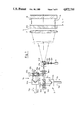
- the schematic of FIG. 1 shows an interferometer which corresponds to the known Fizeau arrangement except for the delay device 10.
- the light source 11 can, for example, be a semiconductor laser.
- the beam emanating from light source 11 is provided with an appropriate aperture angle by means of the lenses (12a, 12b) and the diaphragm 12c and is reflected at the beam splitter cube 12d and is again made parallel by lens 13.
- the parallel beam then passes through the planar plate 14 having the reference surface 14a from which a part (partial beam) of the beam is reflected.
- the other part of the beam passes through the air gap 15 having the optical path length nL 1 and a further part (partial beam) is reflected at the test surface 16.
- the two reflected partial beams then pass through the lens 13, the beam splitter cube 12d, a diaphragm 17a and a lens 17b up to the spatially-resolving receiver 18.
- the test surface 16 and the reference surface 14a are imaged on the receiver 18 by means of the lenses (13 and 17b) with an interference pattern occurring at the receiver.
- the interference pattern can, for example, be evaluated in a known manner as described in the introduction.
- the delay device 10 is important for the invention and includes a beam splitter cube 10a as well as a 90°-angle mirror 10b which can be coarsely adjusted in the directions 10r on a mechanical guide 10m and can be finely adjusted with a piezo element 10p. Those rays which pass over the angle mirror 10b have an optical path difference of 2nV l relative to the remaining rays wherein:
- n is the index of refraction of air
- 2V 1 is the additional path length through the delay path.
- the rays emanating from the light source 11 can reach the receiver 18 along four different optical paths OP:
- the 90°-angle mirror is so positioned on the mechanical guide 10m that for the difference of the optical path OP 2 and OP 3 , the following applies:
- KL is the coherence length of the radiation of the light source 11.
- the interference pattern on the receiver 18 can only arise by means of an interference between the component beams with optical paths OP 2 and OP 3 by suitably selecting the following: the coherence length of the light source 11, the length L 1 of the air gap 15 and the length V 1 of the delay device 10.
- the other component beams do not contribute to the interference pattern; instead, they simply effect a reduction in contrast which, however, can be accepted because of the photoelectric measurement of the irradiated intensity and the way in which the subsequent evaluation is made.
- a recording of at least three interferograms is achieved with the known method described in the introduction with the piezo element 10p being utilized for changing the phase differences.
- FIG. 2 shows an arrangement which is similar to a Fizeau arrangement.
- An advantage of the invention is that the distance between the test surface and the reference surface does not change. Therefore, planar plates can be tested with respect to their planar parallelism.
- the optical phase differences are measured between the surfaces 25a and 25b of the planar plate 25 which for this purpose is mounted downstream of the positive lens 13.
- the optical delay device 20 in this case is an especially advantageous embodiment which includes a beam splitter cube 20a and two retroreflecting devices (20b, 20c).
- the retroreflective devices (20b, 20c) are each made up of a converging lens 20q and a mirror 20s disposed in the focal plane of the converging lens and have the characteristic that they reflect into themselves the parallel rays impinging thereupon independently of the angle of incidence.
- the retroreflective arrangement 20b is coarsely adjustable on the mechanical guide 10m and the reflecting arrangement 20c is finely adjustable with a piezo electric transducer 10p.
- a planar plate 29 is mounted in the beam path ahead of the retroreflecting device 20b, effecting a delay of 2nV 2 wherein n is the index of refraction of the planar plate 29.
- the planar plate 29 should be made from the same type of glass and be of the same thickness as the planar plate 25 to be tested so that the interference pattern on the receiver 18 can be as rich in contrast as possible.
- the radiation emanating from the light source can reach the receiver via four different optical paths.
- the requirements listed above with respect to FIG. 1 apply correspondingly.
- FIG. 3 shows a further embodiment wherein an aspherical surface 34a is tested against a spherical reference surface 36 and for which the delay device 30 is not arranged in the illumination portion.
- the radiation coming from the light source 11 is collimated at lens 12a and is linearly polarized by means of the polarizer 31a in the event that the light source does not already provide polarized light. Thereafter, the direction of oscillation of the light is so adjusted by means of the halfwave plate 31b that it lies at an angle of 45° to the plane of the drawing.
- the lens 12b images the light source on the small diaphragm 12c. The light is deflected by the splitter cube 12d to lens 33 which again collimates the beam.
- the beam is split by the polarization beam splitter 30a into a first component beam polarized perpendicularly to the plane of the drawing and which is reflected to the mirror 30b, and into a second component beam which is polarized parallel to the plane of the drawing and which goes to the mirror 30c.
- These component beams pass through separate lenses (39b and 39a) and are subsequently brought together in a polarization beam splitter 30d.
- the further configuration corresponds completely to a Fizeau Interferometer with an air gap 35 having the optical path length nL 3 between the test surface 34a and the reference surface 36.
- the polarization beam splitter 30d effects a splitting into the correct component beams within the delay device 30.
- An analyzer 38 between the lens 17b and the receiver 18 provides that the two temporally coherent waves, which can cause the desired interference to occur, obtain the same polarization state and therefore can interfere.
- the optical path difference of the delay device 30 is given by the difference of the light paths via the mirrors (30b and 30c). This optical path difference can therefore not be shown as a distance in FIG. 3.
- the polarization beam splitter 30a and the mirror 30b are adjusted such that the optical path difference between, on the one hand, the sum of the optical light paths from the polarization beam splitter 30a via mirror 30b and through the lens 39b up to the splitter surface of the polarization beam splitter 30d, and, on the other hand, the sum of the optical light paths from the polarization beam splitter 30a via mirror 30c and through the lens 39a up to the splitter surface of the polarization beam splitter 30d, correspond to the optical path length nL 3 in the air gap 35 between the surfaces (34a and 36).
- the additional light path after the reflection of the wave on the surface 36 is then compensated on the return of the light in the delay device 30 before the radiation is again united through the polarization optical beam splitter 30a.
- the defined change of the optical path difference by fractions of a wavelength is again obtained with the piezo element 10p which moves the mirror 30c.
- the radiation emanating from the light source can again reach the receiver via four different optical paths which however differ in their polarization planes in the delay device 30.
- the arrangement of the lenses (39a and 39b) within the delay device 30 has the great advantage that the lens 39b acts only together with the test surface 34a, and the lens 39a acts only with the reference surface 36 to create the interference pattern. In this way, it is possible to test the aspherical test surface 34a with the spherical reference surface 36.
- the lens 39b is so designed that it transforms the entering planar wave into a wave which, after passing through the beam splitter 30d and the entrance surface 34b of the aspherical lens 34, takes on the form of this aspherical surface at the location of the surface 34a.
- the lens 39a is so designed that it transforms the entering planar wave into a wave, which after passing through the beam splitter 30d and after passing through the entire aspherical lens 34 and the air gap 35, takes on the form of the spherical reference surface 36.
- the delay device 30 satisfies both functions in the arrangement according to FIG. 3, namely the delay of the optical path for compensating for air gap 35 with the possibility of a defined change of the optical path difference by a fraction of a wavelength on the one hand, and "marking" the waves by means of their polarization on the other hand.
- FIG. 4 it will be shown that these functions can also be separated.
- FIG. 4 shows two interferometers arranged one behind the other, namely, the Mach-Zehnder Interferometer made up of components (40a, 40b, 40c, 39a, 39b, 30d) and the Fizeau-Interferometer comprising components (34 and 36).
- the triple prism 40g can be displaced on a guide 10m in the direction 10r by a distance V 4 .
- the defined change of the optical path difference by fractions of a wavelength again is provided with the piezo element 10p which moves the triple prism 40g.
- the beam emanating from the light source 11 and the lens 12a is first linearly polarized by the polarizer 31a in the event that the light source does not already provide polarized light. Thereafter, the oscillation direction of the light is adjusted by means of the halfwave plate 31b so that it lies at 45 ° to the plane of the drawing.
- the polarization optical beam splitter 40e then reflects the component which oscillates perpendicularly to the plane of incidence (plane of the drawing) to the triple prism 40g, and transmits the component which oscillates parallel to the plane of incidence to the triple prism 40f.
- the recombination after the delay of the component beam having the perpendicular oscillation direction with the other component beam is without loss if the triple prisms do not change the corresponding polarization condition. It is therefore preferable to utilize triple mirrors or to coat the reflecting surfaces of the triple prism with silver layers.
- the arrangement and function of the components (12a, 12b, 12c, 12d, 33, 17a, 17b and 18) correspond to that already described in FIGS. 1 and 2.
- the beam splitter cube 12d is not polarization-active.
- the component group comprising components (40a, 40b, 40c, 39a, 39b, 30d) which represent a special embodiment of a "polarization-active" Mach-Zehnder Interferometer can be considered a special attachment which permits convex aspherical surfaces to be compared to concave spherical surfaces in a Fizeau arrangement downstream. It is evident that also concave aspherical surfaces can be compared to convex spherical surfaces. A large variety of applications are possible due to this modular configuration.
- the splitting and recombining of orthogonally polarized (and simultaneously differently delayed) waves in the Mach-Zehnder Interferometer occurs without loss with the components (40a and 30d) before as well as after the reflection of the waves on these surfaces (34a and 36).
- the transmission axis of the analyzer 38 is adjusted at 45° with respect to the plane of the drawing or can also be adjusted to another angle for different reflectivities of the surfaces (34a and 36).
- the analyzer 38 is mounted in front of the spatially-resolving receiver 18 and provides that the time-coherent waves receive the same polarization condition and can interfere.
- the delay device 40 shown in FIG. 4 can be replaced by means of the delay device 10 shown in FIG. 1 of the polarizer 31a and the halfwave plate 31b are inserted between the lens 12a and the beam splitter 10a and if the splitter layers in the prism 10a are polarizing.
- the delay device 20 shown in FIG. 2 can be modified to a polarization-optically effective delay device.
- two further quarterwave plates are needed which are inserted between the splitter cube 20a and the retroreflecting units (20b, 20c).
- the splitter cube 20a must then be a polarizing splitter cube.
- the first example has as its object to compare the front and back surfaces of a massive plate with respect to each other; however, in this instance, under the assumption that the surfaces enclose a wedge angle.
- FIG. 5 should be seen as a further "accessory" which can be placed ahead of the lens 33 of the arrangement of FIG. 4 in lieu of the components (40a), etc.
- This accessory includes both halfwave plates (50a, 50c), the two Wollaston prisms (50b, 50d), the afocal Kepler telescope having the ocular 51a and the objective 51b as well as the test object 25 having the two surfaces (25a, 25b).
- the component corresponding to this component after the Kepler telescope has an oscillation direction which in the general case is no longer perpendicular to the plane of the drawing and impinges perpendicularly on the front surface 25a of the wedge plate 25.
- the bundle polarized orthogonally hereto must pass through the additional optical path nL 5 before it impinges perpendicularly on the back surface 25b of the wedge plate 25 and, after reflection, again passes through the optical path nL 5 .
- the telescope made from the components (51a, 51b) must have a good field correction which however presents no problem.
- both halfwave plates 50a, 50c
- the edges of the prisms of which both Wollaston prisms are built, are perpendicular to the plane of the drawing of FIG. 5.
- the angle introduced by the first Wollaston prism is immediately cancelled again by the second Wollaston prism.
- Only a small parallel offset of the beam results which is unimportant for the operation of the interferometer.
- the components (50b, 50c and 50d) are moved together as close as possible in order to hold this parallel offset as small as possible.
- the two Wollaston prisms (50b and 50d) are rotated by the same angle in mutually opposite directions about the optical axis for adjusting the finite angle (a').
- the halfwave plate 50a is rotated through an angle by an amount corresponding to half the angle of rotation of the Wollaston prism 50b and in the same rotational direction.
- the halfwave plate 50c remains unchanged.
- the first halfwave plate rotates the polarization directions of the incident beams parallel to the axes of the Wollaston prism 50b so that no mixing of delayed and non-delayed waves occurs.
- the second halfwave plate is stationary.
- the polarization directions are adapted to the Wollaston prism 50d (oscillation direction parallel and perpendicular to the prism edge). In this way, a mixing of delayed and non-delayed waves is again prevented.
- FIG. 6 an embodiment is shown wherein no time change of the relative phase position between comparison wave and test wave occurs; instead, and in lieu thereof, several interferograms are measured simultaneously with several spatially-resolving receivers. These interferograms differ from one another in a defined manner in the relative phase position between comparison wave and test wave. For that purpose, the light in both component arms of the delay device 60 are polarized differently for "marking" the phase. The receiver device 68 utilizes this marking of the test wave and the comparison wave to generate several interferograms (four for example) by means of further polarization-active components. These interferograms differ from one another in a defined manner in the relative phase position between test wave and comparison wave. The function and arrangement of the polarization-optical components is disclosed in U.S.
- Pat. No. 4,360,271 which is incorporated herein by reference.
- This patent shows a Michelson Interferometer without spatially-resolving receivers for the purpose of making length measurements.
- the application for the purpose of interferometric testing with spatially-resolving receivers changes nothing with respect to the modulation and decoding principle.
- the parallel measurement affords the great advantage that the relative phase positions in all measuring channels are changed in the same amount, for example, as a consequence of vibrations and that therefore the phase relationships of the measuring channels are not changed with respect to each other. For this reason, even events which change rapidly with time can be measured.
- the method of parallel measurement can be applied with interferometers for which a modulation of the phase by means of polarization optical methods in the measuring components of the interferometer is not possible or at least is not advantageous.
- a typical example is here again presented by the Fizeau Interferometer of FIG. 1 or of FIG. 2.
- a quarterwave plate must, for example, be inserted in the air gap 15 between the surfaces (14a, 16) in order to polarize the test wave and the reference wave differently. This would be wholly unsuitable because such a large quarter waveplate cannot be produced or at least not with the required quality.
- the insertion of such a plate between the surfaces (25a, 25b) is not at all possible.
- the marking of the test wave and the comparison wave is achieved via different polarization conditions in the delay device 60.
- the operation of the delay device 60 corresponds substantially to that of the delay device 40 shown in FIG. 4.
- the polarizer 31a and the halfwave plate 31b have been added.
- the splitter layers of the beam splitter 60a act here to polarize.
- the roof-edge mirror 10b is now no longer mounted on the piezo element.
- the halfwave plate 31b is adjusted so that the linear polarized light oscillates at 45° to the plane of the drawing.
- the s-component is delayed in the delay device 60 with respect to the p-component by 2nV 1 .
- the decoding device comprises the halfway plate 67a by means of which the oscillation directions of the s-component and of the p-component are both conjointly rotated by 45° to the plane of the drawing.
- the decoding device further includes the non-polarizing beam splitter cube 68a which splits both components and directs the same to the polarizing beam splitter cubes (68b, 68c).
- a quaterwave plate 67b is inserted between the beam splitter 68a and the polarizing beam splitter 68b and effects a phase delay between the s-component and the p-component by pi/2.
- the polarizing beam splitters effect the production of four interferograms for which the phase position between the equally polarized, interfering components of the test wave and the reference wave each differ by pi/2.
- These interferograms are simultaneously measured with the synchronized spatially-resolving receivers (18a, 18b, 18c, 18d).
- the test surface 16 is sharply imaged on the spatially-resolving receivers (18a, 18b, 18c, 18d) by the lenses (13, 17b).
- the focal lengths of the lenses as well as the object distance and image width must be correspondingly selected. In FIG. 6, the proportions are not tightly maintained so that an overview can be provided.
- the optical delay device is disposed in the "illumination part" of the interferometer.
- the cross sections of the beam can be held especially small.
- An arrangement of the delay device in the "observing part" of the interferometer however opens up an entirely new possibility for the simultaneous generation of several phase displaced interferograms without having to apply polarization-optical methods for this purpose. The principle is described with reference to FIG. 7. In FIG. 8, an especially advantageous embodiment is illustrated.
- FIG. 7 a Fizeau Interferometer is again illustrated.
- the beam splitter 68a splits the partial beams reflected from the surfaces (14a, 16) with different delays. These partial beams are first split into two components which are directed to the prisms (70a, 71a). The component reflected to the prism 70a is first observed. The two partial beams contained in this component, which originate from the reflection at the test surface 16 and the reference surface 14a are temporally incoherent and therefore are at first not capable of interference.
- the first splitter surface of the prism 70a splits both partial beams contained in the component in a relationship of 1:1.
- the half reflected at the splitter surface is directed via angle mirror 70b to the second splitter surface of prism 70a and is there united with the other half which in transmission had passed through the first splitter surface of prism 70a.
- the two united halves now contain a portion which is temporally coherent and therefore capable of interference since the one half of the component beam, which was directed via the angle mirror 70b, passed over an additional optical path 2nV 11 which corresponds approximately to the additional optical path 2nL 1 in the air gap between the surfaces (14a, 16).
- the difference of the optical paths between 2nV 11 and 2nL 1 must be less than the coherent length of the light source.
- the angle mirror 70b is displaceable along the direction 70r on the guide path 70m for adjusting the delay V 11 corresponding to the particular distance L 1 .
- the two spatially-resolving detectors (18a, 18b) by means of which two interferograms can be simultaneously measured are located behind the second splitter surface of the prism 70a. In these interferograms, the phase differences between test wave and reference wave differ from each other at each point by pi. The phase difference between the interfering coherent portions of the test wave and the reference wave can be continuously and uniformly changed for the entire interferogram by means of a fine adjustment of the distance V 11 between the prism 70a and the angle mirror 70b.
- a delay 2nV 12 is here adjusted which corresponds approximately to the delay 2nV 11 .
- the phase positions of the interferograms between the detectors (18c, 18d) again differ from each other by an amount pi.
- the angle mirror 70b is finely displaced on its guide path 70m in order to realize the desired relative phase position of pi/2 between the detectors (18a, 18c).
- the test surface 16 should be sharply imaged on the detectors in order to prevent diffraction fringes at the edge of the test object.
- the focal lengths of the lenses (13, 17b) have to be appropriately selected and the optical paths which result from the object distance and the image distance must be appropriately adjusted.
- the object distance and image distance are not presented to scale.
- the transmission paths through the prisms (70a, 71a) are taken as the optical paths specifying the image distance.
- the coherent portion of the partial beam reflected at the reference surface 14a passes via the angle mirrors (70b, 71b). The image distance of this partial beam is then too large.
- two different delays of the partial beam reflected at the reference surface 14a are provided by means of the additional optical paths 2nV 11 and 2nV 12 which are so matched that the desired relative phase positions of the four generated interferograms of 0, pi/2, pi, 3pi/2 result.
- every desired even number of interferograms can be generated pursuant to this principle.
- the arrangement of two spatially-resolving detectors on both outputs of the second splitter surface of the prisms (70a or 71a) affords two advantages: the available light flux is fully utilized; and, the phase difference of pi between the two interferograms applies exactly and must not first be produced by means of an adjustment.
- the available light flux is fully utilized; and, the phase difference of pi between the two interferograms applies exactly and must not first be produced by means of an adjustment.
- the interferograms on the spatially-resolving detectors (18a, 18d) appear as mirror images compared to the interferograms on the spatially-resolving detectors (18b, 18c).
- This situation is disadvantageous if self-scanning synchronized detectors are used for the measurement and the differences of the signals of the detectors (18a, 18b as well as 18c, 18d) are formed immediately by means of an analog differential amplifier.
- a like orientation (not reflected) of the interferograms can be obtained when, for example, a mirror is inserted between the prism 70a and the detector 18a as well as between the prism 71a and the detector 18d.
- a lateral-shear interferometer with the planar parallel shearing plate 81 is illustrated in FIG. 8.
- This shearing interferometer affords the advantage of providing a relatively simple assembly as well as a simple adjustment and low sensitivity to vibration.
- the shear distance is known with a high precision and cannot inadvertently be changed if a massive parallel plate is used as a component which effects a splitting of the wave front to be tested into two component wave fronts sheared with respect to each other.
- the shear distance is a very essential characteristic quantity for the computed evaluation of the interferograms which is performed later.
- Shearing interferometers require no reference wave front which remains uninfluenced by the optical system to be tested. Instead, they derive the reference wave front from the test wave front itself.
- the test wave front is reflected on the front surface 81a and on the back surface 81b of the shearing plate 81 and in this way the test wave front is offset as well as being delayed in time. This time delay is essential for the function of the invention and the lateral offset is essential for the function of the shear interferometer.
- the invention is applicable to all shear interferometers wherein the optical paths of both sheared component waves are either already different or can be made different. This is the case for the vast majority of known arrangements.
- the invention can also be utilized in combination with radiation sources of unusually short coherent length such as obtained from sunlight with a simple color filter reducing the spectral bandwidth to 100 nm.
- the coherence length (KL) is then 2500 nm, that is, there is more than an interference fringe period available for phase measurement.
- the interference fringe period corresponds to an optical path difference of 500 nm.
- the entrance pupil of the telescope is imaged on the spatially-resolving receivers (18a, 18b, 18c, 18d) and the bright reference star is imaged in the diaphragm 17a.
- the measurement of the fast-changing wave front is, for example, necessary to compensate for the "seeing" caused by the atmosphere utilizing an active optical component. Because of the small necessary time constant for the control it is especially important to generate several phase shifted interferograms which can be read out simultaneously.
- the principle described with respect to FIG. 7 is applied for the simultaneous detection of four phase-displaced interferograms here, however, in another embodiment.
- the beam collimated by the lens 17b is now split into two parallel beams with a Kosters prism 80a. This makes it possible to unite the two beam splitters (70a, 71a) of the delay device of FIG. 7 into a single component 80b.
- the roof-edge mirrors (70b, 71b) of FIG. 7 are now replaced by a single roof-edge prism 80c (see FIG. 8a).
- One of the waves passes additionally through the sum of the optical paths (81c, 81d) for realizing the lateral shear in the shear plate 81 and the sum of these optical paths (81c, 81d) corresponds to approximately the optical path in the roof-edge prism 80c. It is then preferable to select the optical path in the roof-edge prism 80c to be somewhat smaller than the additional optical path in the shearing plate so that the delay of the delay device can be adjusted by displacing the roof-edge prism 80c on the guide 10m along the direction 10r.
- the shear plate and the roof-edge prism are advantageously made of the same glass material. A total of four phase shifted interferograms are generated with the delay device 80 described here.
- this delay device 80 it is essential that the interferograms on the detectors (18a, 18c) are phase-shifted with respect to each other by a fixed phase angle which is preferably pi/2. The same applies then for the interferograms on the detectors (18b, 18d).
- a thin layer is vapor-deposited on the one half of the base side of the roof edge prism (the partition line extends perpendicularly to the 90°-edge of the prism). This thin layer then defines an additional optical path of quarter wave for the beam which passes through. The quarter wave corresponds to an eighth wave when the beam enters and another eighth wave when it exits the prism.
- the index of refraction being (n) for the layer
- the index of refraction (n) is then so selected that it is possible to subsequently vapor-deposit reflection-reducing layers onto the entire base side of the roof-edge prism.
- the simplest circumstances are obtained when the index of refraction of the layer and of the prism material differ from each other as little as possible.
- the prism 80c it is possible to start with a fixed predetermined delay of the waves in the measuring part of the interferometer. For reasons of the stability of the adjustment, it is then preferable to tightly glue the prism 80c to the beam splitter 80b.
- the optical path difference of ⁇ /4 can be obtained for both halves of the prism in that, for example, an appropriate layer is vapor-deposit onto half of one of the short faces.
- FIG. 9 A still further embodiment of the invention is shown in FIG. 9 wherein the invention is applied to a Mach-Zehnder Interferometer.
- This type of interferometer is often used for investigating boundary layers, flow and convection processes, temperature distributions and the like in transparent gases or liquids.
- large beam cross sections or a large "test volume” 95 is needed.
- the optical path length (and therefore the phase) for example of the reference arm of the interferometer is changed in a defined manner in that, for example, the large mirror 91b is displaced mechanically or piezo-electrically by a fraction of a wavelength.
- this application fails here because of the size of the mirror.
- the delay device 90 is mounted between the light source 11 and the pinhole diaphragm 12c.
- the coherence length of the light source is again less than the optical light path 2nL 9 which is additionally passed through by the second component wave in the reference arm of the Mach-Zehnder Interferometer.
- the interference capability between the component waves is again established by means of the optical delay device 90.
- the optical delay device 90 here comprises the Kosters prism 90a, the two triple prisms (90f, 90g) as well as the surface mirrors (90c, 90d) which are vapor deposited onto the exit surface of the Kosters prism. In this delay device, tilting as well as lateral displacement of the triple prisms have no harmful effect.
- the triple prism 90g is adjustable on a guide path 10m in the direction 10r for adjusting the coherence.
- the triple prism 90f is mounted on a piezo element 10p for providing defined changes of the phase position of the component waves.
- the triple prism 90g is displaced on the guide path 10m in the direction 10r by an amount V 9 ⁇ L 9 /2 for compensating for the additional optical path 2nL 9 of the second component wave in the Mach-Zehnder Interferometer.
- compensation can be achieved by inserting a corresponding "reference volume" into the reference arm of the Mach-Zehnder Interferometer between the mirrors (91b and 91d).
- the reference volume is then filled with a medium having the same index of refraction.
- the beams which are time delayed differently are again united by the Kosters prism 90a and expanded with the lenses (12b, 93a).
- the small diaphragm 12c lying between the lenses (12b, 93a) serves to clean the beams.
- the beam now enters the Mach-Zehnder Interferometer consisting of the two beam splitters (91a, 91c) and the two mirrors (91b, 91d).
- the test volume 95 is imaged on the spatially-resolving detector 18 on which the interferences arise, by means of the lenses (93b, 17b).
- the diaphragm 17a eliminates possible disturbing interferences which can originate on the rearward side of the beam splitter plates which are slightly wedge-shaped.
Abstract
Description
|OP.sub.2 -OP.sub.3 |<<KL
|OP.sub.1 -OP.sub.2 |>>KL
|OP.sub.1 -OP.sub.3 |>>KL
|OP.sub.1 -OP.sub.4 |>>KL
|OP.sub.2 -OP.sub.4 |>>KL
|OP.sub.3 -OP.sub.4 |>>KL
Claims (16)
Applications Claiming Priority (2)
| Application Number | Priority Date | Filing Date | Title |
|---|---|---|---|
| DE19873707331 DE3707331A1 (en) | 1987-03-07 | 1987-03-07 | INTERFEROMETER FOR MEASURING OPTICAL PHASE DIFFERENCES |
| DE3707331 | 1987-03-07 |
Publications (1)
| Publication Number | Publication Date |
|---|---|
| US4872755A true US4872755A (en) | 1989-10-10 |
Family
ID=6322483
Family Applications (1)
| Application Number | Title | Priority Date | Filing Date |
|---|---|---|---|
| US07/164,790 Expired - Lifetime US4872755A (en) | 1987-03-07 | 1988-03-07 | Interferometer for measuring optical phase differences |
Country Status (4)
| Country | Link |
|---|---|
| US (1) | US4872755A (en) |
| EP (1) | EP0281906B1 (en) |
| CA (1) | CA1316367C (en) |
| DE (2) | DE3707331A1 (en) |
Cited By (74)
| Publication number | Priority date | Publication date | Assignee | Title |
|---|---|---|---|---|
| US5017986A (en) * | 1989-08-28 | 1991-05-21 | At&T Bell Laboratories | Optical device mounting apparatus |
| GB2253493A (en) * | 1991-01-29 | 1992-09-09 | Clark Instrumentation Inc | Method and apparatus relating to an optical delay line |
| US5305074A (en) * | 1992-07-17 | 1994-04-19 | The United States Of America As Represented By The United States Department Of Energy | Achromatic self-referencing interferometer |
| US5361312A (en) * | 1990-05-02 | 1994-11-01 | Carl-Zeiss-Stiftung | Method and apparatus for phase evaluation of pattern images used in optical measurement |
| US5416586A (en) * | 1993-10-15 | 1995-05-16 | Tropel Corporation | Method of testing aspherical optical surfaces with an interferometer |
| US5452088A (en) * | 1994-03-18 | 1995-09-19 | Wyko Corporation | Multimode-laser interferometric apparatus for eliminating background interference fringes from thin-plate measurements |
| EP0676629A2 (en) * | 1994-04-05 | 1995-10-11 | Carl Zeiss | Refractive index measurement of spectacle lenses |
| US5488477A (en) * | 1993-11-15 | 1996-01-30 | Zygo Corporation | Methods and apparatus for profiling surfaces of transparent objects |
| US5502302A (en) * | 1993-09-17 | 1996-03-26 | Agfa-Gevaert, N.V. | Scratch-suppressing scanning apparatus with aspherical lens |
| WO1996017221A1 (en) * | 1994-11-28 | 1996-06-06 | The Regents Of The University Of California | Phase shifting diffraction interferometer |
| US5561525A (en) * | 1993-06-21 | 1996-10-01 | Nikon Corporation | Interferometer for observing the interference pattern of a surface under test utilizing an adjustable aperture stop |
| US5822066A (en) * | 1997-02-26 | 1998-10-13 | Ultratech Stepper, Inc. | Point diffraction interferometer and pin mirror for use therewith |
| EP1178347A2 (en) * | 2000-08-01 | 2002-02-06 | JDS Uniphase Inc. | Virtual waveplate and optical channel interleaver formed therewith |
| US20020126292A1 (en) * | 2000-05-03 | 2002-09-12 | The Regents Of The University Of California | Wollaston prism phase-stepping point diffraction interferometer and method |
| NL1018344C2 (en) * | 2001-06-20 | 2002-12-30 | Tno | Interferometer. |
| US20030011784A1 (en) * | 2001-07-12 | 2003-01-16 | De Groot Peter J. | Measurement of complex surface shapes using a spherical wavefront |
| US20030090677A1 (en) * | 2001-11-14 | 2003-05-15 | Evans Christopher James | Methods and apparatus for interferometric dimensional metrology |
| WO2003102655A1 (en) * | 2002-05-30 | 2003-12-11 | The University Court Of The University Of Glasgow | Photonic switch working in momentum-divison-multiple-access (mdma) mode for microwave and optical wavelengths based upon the measurement of the spin, the orbital angular momentum and the total angular momentum of the involved photo |
| US6674533B2 (en) | 2000-12-21 | 2004-01-06 | Joseph K. Price | Anodizing system with a coating thickness monitor and an anodized product |
| US20040012791A1 (en) * | 2002-06-17 | 2004-01-22 | Lega Xavier Colonna De | Interferometer having a coupled cavity geometry for use with an extended source |
| US20040027576A1 (en) * | 2002-06-17 | 2004-02-12 | De Groot Peter J. | Interferometric optical systems having simultaneously scanned optical path length and focus |
| US6717680B1 (en) | 2001-05-25 | 2004-04-06 | Zygo Corp | Apparatus and method for phase-shifting interferometry |
| US6771375B2 (en) * | 2001-06-20 | 2004-08-03 | Zygo Corporation | Apparatus and method for measuring aspherical optical surfaces and wavefronts |
| US20040196469A1 (en) * | 2003-04-01 | 2004-10-07 | Seagate Technology Llc | Optical profiler for ultra-smooth surface with normal incident beam deflection method |
| US6806963B1 (en) * | 1999-11-24 | 2004-10-19 | Haag-Streit Ag | Method and device for measuring the optical properties of at least two regions located at a distance from one another in a transparent and/or diffuse object |
| US20040252311A1 (en) * | 2001-09-27 | 2004-12-16 | Nikon Corporation | Method and apparatus for point diffraction interferometry |
| US20050046865A1 (en) * | 2003-08-28 | 2005-03-03 | Brock Neal J. | Pixelated phase-mask interferometer |
| US20050046864A1 (en) * | 2003-08-28 | 2005-03-03 | Millerd James E. | Simultaneous phase-shifting fizeau interferometer |
| US20050134863A1 (en) * | 2003-12-18 | 2005-06-23 | De Lega Xavier Colonna | Interferometric microscopy using reflective optics for complex surface shapes |
| US20050139159A1 (en) * | 2003-12-30 | 2005-06-30 | Price Joseph K. | Anodizing system with a coating thickness monitor and an anodized product |
| US20050196522A1 (en) * | 2000-12-21 | 2005-09-08 | Price Joseph K. | System capable of determining applied and anodized coating thickness of a coated-anodized product |
| US20060098210A1 (en) * | 2004-10-13 | 2006-05-11 | Carl Zeiss Smt Ag | Projection exposure system and method of manufacturing a miniaturized device |
| US7061613B1 (en) | 2004-01-13 | 2006-06-13 | Nanometrics Incorporated | Polarizing beam splitter and dual detector calibration of metrology device having a spatial phase modulation |
| US7064828B1 (en) | 2001-12-19 | 2006-06-20 | Nanometrics Incorporated | Pulsed spectroscopy with spatially variable polarization modulation element |
| US20060146334A1 (en) * | 2002-09-18 | 2006-07-06 | Cluff Julian A | Apparatus for varying the path length of a beam of radiation |
| US20060146341A1 (en) * | 2002-11-27 | 2006-07-06 | Piotr Szwaykowski | Interferometric system with reduced vibration sensitivity and realated method |
| US7289222B1 (en) * | 2003-10-31 | 2007-10-30 | Carl Zeiss Smt Ag | Interferometer apparatus and method of processing a substrate having an optical surface |
| EP1890105A1 (en) * | 2006-08-14 | 2008-02-20 | Carl Zeiss SMT AG | Interferometer apparatus and interferometric method |
| US20080062428A1 (en) * | 2006-09-07 | 2008-03-13 | 4D Technology Corporation | Synchronous frequency-shift mechanism in Fizeau interferometer |
| US20080117436A1 (en) * | 2005-03-30 | 2008-05-22 | Carl Zeiss Smt Ag | Method of manufacturing an optical element |
| US20090002663A1 (en) * | 2005-11-29 | 2009-01-01 | Carl Zeiss Smt Ag | Projection illumination system |
| US7483145B2 (en) | 2002-11-27 | 2009-01-27 | Trology, Llc | Simultaneous phase shifting module for use in interferometry |
| CN100492179C (en) * | 2007-07-10 | 2009-05-27 | 上海微电子装备有限公司 | Interferometer |
| CN100492180C (en) * | 2007-07-10 | 2009-05-27 | 上海微电子装备有限公司 | Projection objective detecting method |
| CN100535760C (en) * | 2007-07-10 | 2009-09-02 | 上海微电子装备有限公司 | On-line testing apparatus of projection objective |
| US20090231593A1 (en) * | 2005-05-24 | 2009-09-17 | Carl Zeiss Smt Ag | Method of aligning an optical system |
| DE102008030664A1 (en) | 2008-07-01 | 2010-01-21 | Carl Zeiss Smt Ag | Optical imaging device with determination of aberrations |
| US20100134801A1 (en) * | 2006-09-07 | 2010-06-03 | 4D Technology Corporation | Synchronous frequency-shift mechanism in fizeau interferometer |
| US20100145648A1 (en) * | 2008-08-08 | 2010-06-10 | The Regents Of The University Of Colorado, A Body Corporate | System and method for correcting sampling errors associated with radiation source tuning rate fluctuations in swept-wavelength interferometry |
| US7751064B2 (en) | 2008-01-22 | 2010-07-06 | Zygo Corporation | Interference objective for annular test surfaces |
| US20110235058A1 (en) * | 2006-03-07 | 2011-09-29 | Price Joseph K | Mobile Apparatus Capable of Surface Measurements |
| US20110292402A1 (en) * | 2009-02-13 | 2011-12-01 | National University Corporation Kyoto Institute Of Technology | Interference measurement apparatus and method for measuring interference |
| US20110299090A1 (en) * | 2010-06-07 | 2011-12-08 | Fujifilm Corporation | Real-time interferometer |
| US8269980B1 (en) | 2009-05-11 | 2012-09-18 | Engineering Synthesis Design, Inc. | White light scanning interferometer with simultaneous phase-shifting module |
| US20140104619A1 (en) * | 2007-02-21 | 2014-04-17 | Agfa Healthcare Nv | System and Method for Optical Coherence Tomography |
| US9103649B2 (en) | 2011-09-08 | 2015-08-11 | Zygo Corporation | In situ calibration of interferometers |
| JP2016114362A (en) * | 2014-12-10 | 2016-06-23 | 株式会社オキサイド | Double image inspection system |
| US9534883B1 (en) | 2011-11-22 | 2017-01-03 | Engineering Synthesis Design, Inc. | Methods for determining error in an interferometry system |
| US9857169B1 (en) | 2015-12-21 | 2018-01-02 | 4D Technology Corporation | Single-step interferometric radius-of-curvature measurements utilizing short-coherence sources |
| US20180149463A1 (en) * | 2016-11-30 | 2018-05-31 | Apre Instruments, Llc | Extending the range of spectrally controlled interferometry by superposition of multiple spectral modulations |
| US10101667B2 (en) | 2014-04-04 | 2018-10-16 | Carl Zeiss Smt Gmbh | Method for aligning a mirror of a microlithographic projection exposure apparatus |
| US20190128774A1 (en) * | 2017-10-27 | 2019-05-02 | Harris Corporation | Qtip - quantitative test interferometric plate |
| US20190186904A1 (en) * | 2016-10-18 | 2019-06-20 | Huaiyin Normal University | Asymmetric optical interference measurement method and apparatus |
| US20190277760A1 (en) * | 2018-03-09 | 2019-09-12 | The Boeing Company | Specular variable angle absolute reflectance method and reflectometer |
| CN110319939A (en) * | 2019-06-28 | 2019-10-11 | 南京理工大学 | Polarize the short-coherence light source system and experimental method of phase shift combination PZT phase shift |
| CN111578832A (en) * | 2020-04-30 | 2020-08-25 | 南京理工大学 | Short coherent light source interferometer-based long-stroke optical path matching device and experimental method |
| US10809055B2 (en) * | 2018-07-24 | 2020-10-20 | Kla Corporation | Apparatus and method for measuring topography and gradient of the surfaces, shape, and thickness of patterned and unpatterned wafers |
| US20210042909A1 (en) * | 2019-08-07 | 2021-02-11 | Kimball Electronics Indiana, Inc. | Imaging system for surface inspection |
| US11262191B1 (en) * | 2018-07-12 | 2022-03-01 | Onto Innovation Inc. | On-axis dynamic interferometer and optical imaging systems employing the same |
| CN114111999A (en) * | 2020-08-27 | 2022-03-01 | 精工爱普生株式会社 | Laser interferometer |
| US20220065617A1 (en) * | 2019-05-10 | 2022-03-03 | Nikon Corporation | Determination of a change of object's shape |
| US11327013B2 (en) | 2020-05-15 | 2022-05-10 | The Boeing Company | Specular variable angle absolute reflectance method and reflectometer |
| WO2023096832A1 (en) * | 2021-11-24 | 2023-06-01 | Corning Incorporated | Low-coherence interferometer with surface power compensation |
| US11867507B1 (en) * | 2023-05-05 | 2024-01-09 | Mloptic Corp. | Extended reality virtual distance measurement system |
Families Citing this family (6)
| Publication number | Priority date | Publication date | Assignee | Title |
|---|---|---|---|---|
| FR2645981B1 (en) * | 1989-04-17 | 1991-07-26 | Aerospatiale | DEVICE FOR CONTROLLING THE MOVEMENT WITHOUT VIBRATION OF AN OPTICAL ELEMENT IN A STELLAR INTERFEROMETER AND STELLAR INTERFEROMETER COMPRISING SAME |
| DE4016731C3 (en) * | 1990-05-24 | 2001-04-26 | Bruker Analytik Gmbh | Fourier spectrometer |
| JPH07239272A (en) * | 1994-02-28 | 1995-09-12 | Ando Electric Co Ltd | Optical wavelength meter |
| DE19730572C2 (en) * | 1996-08-05 | 2001-06-21 | Deutsche Telekom Ag | Interferometer and method for compensating the dispersion or for increasing the spectral resolution of such an interferometer |
| DE10360078A1 (en) * | 2003-12-20 | 2005-07-21 | Robert Bosch Gmbh | Optical measuring device |
| US10222615B2 (en) * | 2017-05-26 | 2019-03-05 | Microsoft Technology Licensing, Llc | Optical waveguide with coherent light source |
Citations (2)
| Publication number | Priority date | Publication date | Assignee | Title |
|---|---|---|---|---|
| US4360271A (en) * | 1978-01-13 | 1982-11-23 | National Research Development Corporation | Interferometer systems |
| US4596466A (en) * | 1980-11-24 | 1986-06-24 | Reinhard Ulrich | Method for the measurement of lengths and displacements |
Family Cites Families (4)
| Publication number | Priority date | Publication date | Assignee | Title |
|---|---|---|---|---|
| DE1085350B (en) * | 1957-07-02 | 1960-07-14 | Leitz Ernst Gmbh | Interferometer |
| NL8005258A (en) * | 1980-09-22 | 1982-04-16 | Philips Nv | INTERFEROMETER. |
| US4468122A (en) * | 1981-09-01 | 1984-08-28 | Vysshee Voennoe Tekhnicheskoe Uchilische Imeni N.E. Baumana | Interferometer for checking the shape of convex surfaces of optical components |
| US4688940A (en) * | 1985-03-12 | 1987-08-25 | Zygo Corporation | Heterodyne interferometer system |
-
1987
- 1987-03-07 DE DE19873707331 patent/DE3707331A1/en not_active Withdrawn
-
1988
- 1988-03-02 EP EP88103114A patent/EP0281906B1/en not_active Expired - Lifetime
- 1988-03-02 DE DE88103114T patent/DE3885773D1/en not_active Expired - Lifetime
- 1988-03-07 CA CA000560751A patent/CA1316367C/en not_active Expired - Lifetime
- 1988-03-07 US US07/164,790 patent/US4872755A/en not_active Expired - Lifetime
Patent Citations (2)
| Publication number | Priority date | Publication date | Assignee | Title |
|---|---|---|---|---|
| US4360271A (en) * | 1978-01-13 | 1982-11-23 | National Research Development Corporation | Interferometer systems |
| US4596466A (en) * | 1980-11-24 | 1986-06-24 | Reinhard Ulrich | Method for the measurement of lengths and displacements |
Non-Patent Citations (4)
| Title |
|---|
| "Direct Measurement of Phase in a Spherical-Wave Fizeau Interferomenter" by R. C. Moore and F. H. Slaymaker, (Applied Optics, vol. 19, No. 13, 7-1-1980, pp. 2196 to 2200. |
| "Instantaneous Phase Measuring Interferometry" by R. Smythe and R. Moore, (Optical Engineering, Jul.-Aug. 1984, vol. 23, No. 4, pp. 361 to 364). |
| Direct Measurement of Phase in a Spherical Wave Fizeau Interferomenter by R. C. Moore and F. H. Slaymaker, (Applied Optics, vol. 19, No. 13, 7 1 1980, pp. 2196 to 2200. * |
| Instantaneous Phase Measuring Interferometry by R. Smythe and R. Moore, (Optical Engineering, Jul. Aug. 1984, vol. 23, No. 4, pp. 361 to 364). * |
Cited By (122)
| Publication number | Priority date | Publication date | Assignee | Title |
|---|---|---|---|---|
| US5017986A (en) * | 1989-08-28 | 1991-05-21 | At&T Bell Laboratories | Optical device mounting apparatus |
| US5361312A (en) * | 1990-05-02 | 1994-11-01 | Carl-Zeiss-Stiftung | Method and apparatus for phase evaluation of pattern images used in optical measurement |
| GB2253493A (en) * | 1991-01-29 | 1992-09-09 | Clark Instrumentation Inc | Method and apparatus relating to an optical delay line |
| US5305074A (en) * | 1992-07-17 | 1994-04-19 | The United States Of America As Represented By The United States Department Of Energy | Achromatic self-referencing interferometer |
| US5561525A (en) * | 1993-06-21 | 1996-10-01 | Nikon Corporation | Interferometer for observing the interference pattern of a surface under test utilizing an adjustable aperture stop |
| US5502302A (en) * | 1993-09-17 | 1996-03-26 | Agfa-Gevaert, N.V. | Scratch-suppressing scanning apparatus with aspherical lens |
| US5416586A (en) * | 1993-10-15 | 1995-05-16 | Tropel Corporation | Method of testing aspherical optical surfaces with an interferometer |
| US5488477A (en) * | 1993-11-15 | 1996-01-30 | Zygo Corporation | Methods and apparatus for profiling surfaces of transparent objects |
| US5452088A (en) * | 1994-03-18 | 1995-09-19 | Wyko Corporation | Multimode-laser interferometric apparatus for eliminating background interference fringes from thin-plate measurements |
| EP0676629A2 (en) * | 1994-04-05 | 1995-10-11 | Carl Zeiss | Refractive index measurement of spectacle lenses |
| US5469261A (en) * | 1994-04-05 | 1995-11-21 | Carl Zeiss, Inc. | Measurement of lens characteristics |
| EP0676629B1 (en) * | 1994-04-05 | 2002-02-20 | Carl Zeiss | Refractive index measurement of spectacle lenses |
| WO1996017221A1 (en) * | 1994-11-28 | 1996-06-06 | The Regents Of The University Of California | Phase shifting diffraction interferometer |
| US5933236A (en) * | 1994-11-28 | 1999-08-03 | The Regents Of The University Of California | Phase shifting interferometer |
| US5548403A (en) * | 1994-11-28 | 1996-08-20 | The Regents Of The University Of California | Phase shifting diffraction interferometer |
| US5822066A (en) * | 1997-02-26 | 1998-10-13 | Ultratech Stepper, Inc. | Point diffraction interferometer and pin mirror for use therewith |
| US6806963B1 (en) * | 1999-11-24 | 2004-10-19 | Haag-Streit Ag | Method and device for measuring the optical properties of at least two regions located at a distance from one another in a transparent and/or diffuse object |
| US20020126292A1 (en) * | 2000-05-03 | 2002-09-12 | The Regents Of The University Of California | Wollaston prism phase-stepping point diffraction interferometer and method |
| US6804009B2 (en) | 2000-05-03 | 2004-10-12 | The Regents Of The University Of California | Wollaston prism phase-stepping point diffraction interferometer and method |
| EP1178347A2 (en) * | 2000-08-01 | 2002-02-06 | JDS Uniphase Inc. | Virtual waveplate and optical channel interleaver formed therewith |
| EP1178347A3 (en) * | 2000-08-01 | 2002-02-27 | JDS Uniphase Inc. | Virtual waveplate and optical channel interleaver formed therewith |
| US6570711B2 (en) | 2000-08-01 | 2003-05-27 | Jds Uniphase Inc. | Virtual waveplate and optical channel interleaver formed therewith |
| US20050139476A1 (en) * | 2000-12-21 | 2005-06-30 | Price Joseph K. | Anodizing system with a coating thickness monitor and an anodized product |
| US20040231993A1 (en) * | 2000-12-21 | 2004-11-25 | Price Joseph K. | Anodizing system with a coating thickness monitor and an anodized product |
| US7128985B2 (en) | 2000-12-21 | 2006-10-31 | Sensory Analytics, Llc | Anodizing system with a coating thickness monitor and an anodized product |
| US6674533B2 (en) | 2000-12-21 | 2004-01-06 | Joseph K. Price | Anodizing system with a coating thickness monitor and an anodized product |
| US20050196522A1 (en) * | 2000-12-21 | 2005-09-08 | Price Joseph K. | System capable of determining applied and anodized coating thickness of a coated-anodized product |
| US7365860B2 (en) | 2000-12-21 | 2008-04-29 | Sensory Analytics | System capable of determining applied and anodized coating thickness of a coated-anodized product |
| US7537681B2 (en) | 2000-12-21 | 2009-05-26 | Sensory Analytics | Method for forming and measuring the thickness of an anodized coating |
| US6717680B1 (en) | 2001-05-25 | 2004-04-06 | Zygo Corp | Apparatus and method for phase-shifting interferometry |
| US6771375B2 (en) * | 2001-06-20 | 2004-08-03 | Zygo Corporation | Apparatus and method for measuring aspherical optical surfaces and wavefronts |
| WO2003001166A1 (en) * | 2001-06-20 | 2003-01-03 | Nederlandse Organisatie Voor Toegepast-Natuurwetenschappelijk Onderzoek Tno | Interferometer |
| NL1018344C2 (en) * | 2001-06-20 | 2002-12-30 | Tno | Interferometer. |
| US20030011784A1 (en) * | 2001-07-12 | 2003-01-16 | De Groot Peter J. | Measurement of complex surface shapes using a spherical wavefront |
| US20040252311A1 (en) * | 2001-09-27 | 2004-12-16 | Nikon Corporation | Method and apparatus for point diffraction interferometry |
| US6963408B2 (en) | 2001-09-27 | 2005-11-08 | Nikon Corporation | Method and apparatus for point diffraction interferometry |
| US20060114475A1 (en) * | 2001-10-16 | 2006-06-01 | De Groot Peter J | Measurement of complex surface shapes using a spherical wavefront |
| US7030996B2 (en) | 2001-10-16 | 2006-04-18 | Zygo Corporation | Measurement of complex surface shapes using a spherical wavefront |
| US6714307B2 (en) | 2001-10-16 | 2004-03-30 | Zygo Corporation | Measurement of complex surface shapes using a spherical wavefront |
| US20040239947A1 (en) * | 2001-10-16 | 2004-12-02 | Zygo Corporation, A Delaware Corporation | Measurement of complex surface shapes using a spherical wavefront |
| US7126698B2 (en) | 2001-10-16 | 2006-10-24 | Zygo Corporation | Measurement of complex surface shapes using a spherical wavefront |
| US6801323B2 (en) * | 2001-11-14 | 2004-10-05 | Zygo Corporation | Methods and apparatus for interferometric dimensional metrology |
| US20030090677A1 (en) * | 2001-11-14 | 2003-05-15 | Evans Christopher James | Methods and apparatus for interferometric dimensional metrology |
| US7064828B1 (en) | 2001-12-19 | 2006-06-20 | Nanometrics Incorporated | Pulsed spectroscopy with spatially variable polarization modulation element |
| WO2003102655A1 (en) * | 2002-05-30 | 2003-12-11 | The University Court Of The University Of Glasgow | Photonic switch working in momentum-divison-multiple-access (mdma) mode for microwave and optical wavelengths based upon the measurement of the spin, the orbital angular momentum and the total angular momentum of the involved photo |
| US20050259914A1 (en) * | 2002-05-30 | 2005-11-24 | The University Court Of The University Of Glasgow | Photonic switch working in momentum-division-multiple-access (mdma) mode for microwave and optical wavelengths based upon the measurement of the spin, the orbital angular momentum and the total angular momentum of the involved photo |
| US20040027576A1 (en) * | 2002-06-17 | 2004-02-12 | De Groot Peter J. | Interferometric optical systems having simultaneously scanned optical path length and focus |
| US7046371B2 (en) | 2002-06-17 | 2006-05-16 | Zygo Corporation | Interferometer having a coupled cavity geometry for use with an extended source |
| US7012700B2 (en) | 2002-06-17 | 2006-03-14 | Zygo Corporation | Interferometric optical systems having simultaneously scanned optical path length and focus |
| US20040012791A1 (en) * | 2002-06-17 | 2004-01-22 | Lega Xavier Colonna De | Interferometer having a coupled cavity geometry for use with an extended source |
| US20060146334A1 (en) * | 2002-09-18 | 2006-07-06 | Cluff Julian A | Apparatus for varying the path length of a beam of radiation |
| US7483145B2 (en) | 2002-11-27 | 2009-01-27 | Trology, Llc | Simultaneous phase shifting module for use in interferometry |
| US20120026507A1 (en) * | 2002-11-27 | 2012-02-02 | Piotr Szwaykowski | Interferometric system with reduced vibration sensitivity and related method |
| US20060146341A1 (en) * | 2002-11-27 | 2006-07-06 | Piotr Szwaykowski | Interferometric system with reduced vibration sensitivity and realated method |
| US8004687B2 (en) * | 2002-11-27 | 2011-08-23 | Trology, Llc | Interferometric system with reduced vibration sensitivity and related method |
| US20040196469A1 (en) * | 2003-04-01 | 2004-10-07 | Seagate Technology Llc | Optical profiler for ultra-smooth surface with normal incident beam deflection method |
| US7916308B2 (en) * | 2003-04-01 | 2011-03-29 | Seagate Technology Llc | Method and optical profiler |
| US7230718B2 (en) | 2003-08-28 | 2007-06-12 | 4D Technology Corporation | Simultaneous phase-shifting fizeau interferometer |
| US20050046865A1 (en) * | 2003-08-28 | 2005-03-03 | Brock Neal J. | Pixelated phase-mask interferometer |
| US7230717B2 (en) | 2003-08-28 | 2007-06-12 | 4D Technology Corporation | Pixelated phase-mask interferometer |
| US20060203251A1 (en) * | 2003-08-28 | 2006-09-14 | Millerd James E | Simultaneous phase-shifting fizeau interferometer |
| US20050046864A1 (en) * | 2003-08-28 | 2005-03-03 | Millerd James E. | Simultaneous phase-shifting fizeau interferometer |
| US7057738B2 (en) | 2003-08-28 | 2006-06-06 | A D Technology Corporation | Simultaneous phase-shifting Fizeau interferometer |
| US7289222B1 (en) * | 2003-10-31 | 2007-10-30 | Carl Zeiss Smt Ag | Interferometer apparatus and method of processing a substrate having an optical surface |
| US7212291B2 (en) | 2003-12-18 | 2007-05-01 | Zygo Corporation | Interferometric microscopy using reflective optics for complex surface shapes |
| US20050134863A1 (en) * | 2003-12-18 | 2005-06-23 | De Lega Xavier Colonna | Interferometric microscopy using reflective optics for complex surface shapes |
| US7274463B2 (en) | 2003-12-30 | 2007-09-25 | Sensory Analytics | Anodizing system with a coating thickness monitor and an anodized product |
| US20050139159A1 (en) * | 2003-12-30 | 2005-06-30 | Price Joseph K. | Anodizing system with a coating thickness monitor and an anodized product |
| US7061613B1 (en) | 2004-01-13 | 2006-06-13 | Nanometrics Incorporated | Polarizing beam splitter and dual detector calibration of metrology device having a spatial phase modulation |
| US20060098210A1 (en) * | 2004-10-13 | 2006-05-11 | Carl Zeiss Smt Ag | Projection exposure system and method of manufacturing a miniaturized device |
| US7508488B2 (en) | 2004-10-13 | 2009-03-24 | Carl Zeiss Smt Ag | Projection exposure system and method of manufacturing a miniaturized device |
| US20080117436A1 (en) * | 2005-03-30 | 2008-05-22 | Carl Zeiss Smt Ag | Method of manufacturing an optical element |
| US7738117B2 (en) | 2005-03-30 | 2010-06-15 | Carl Zeiss Smt Ag | Method of manufacturing an optical element |
| US7643149B2 (en) | 2005-05-24 | 2010-01-05 | Carl Zeiss Smt Ag | Method of aligning an optical system |
| US20090231593A1 (en) * | 2005-05-24 | 2009-09-17 | Carl Zeiss Smt Ag | Method of aligning an optical system |
| US8228485B2 (en) | 2005-11-29 | 2012-07-24 | Carl Zeiss Smt Gmbh | Projection illumination system |
| US20090002663A1 (en) * | 2005-11-29 | 2009-01-01 | Carl Zeiss Smt Ag | Projection illumination system |
| US20110235058A1 (en) * | 2006-03-07 | 2011-09-29 | Price Joseph K | Mobile Apparatus Capable of Surface Measurements |
| EP1890105A1 (en) * | 2006-08-14 | 2008-02-20 | Carl Zeiss SMT AG | Interferometer apparatus and interferometric method |
| US8345258B2 (en) | 2006-09-07 | 2013-01-01 | 4 D Technology Corporation | Synchronous frequency-shift mechanism in fizeau interferometer |
| US7675628B2 (en) | 2006-09-07 | 2010-03-09 | 4D Technology Corporation | Synchronous frequency-shift mechanism in Fizeau interferometer |
| US20100134801A1 (en) * | 2006-09-07 | 2010-06-03 | 4D Technology Corporation | Synchronous frequency-shift mechanism in fizeau interferometer |
| US20080062428A1 (en) * | 2006-09-07 | 2008-03-13 | 4D Technology Corporation | Synchronous frequency-shift mechanism in Fizeau interferometer |
| US20140104619A1 (en) * | 2007-02-21 | 2014-04-17 | Agfa Healthcare Nv | System and Method for Optical Coherence Tomography |
| CN100492180C (en) * | 2007-07-10 | 2009-05-27 | 上海微电子装备有限公司 | Projection objective detecting method |
| CN100492179C (en) * | 2007-07-10 | 2009-05-27 | 上海微电子装备有限公司 | Interferometer |
| CN100535760C (en) * | 2007-07-10 | 2009-09-02 | 上海微电子装备有限公司 | On-line testing apparatus of projection objective |
| US7751064B2 (en) | 2008-01-22 | 2010-07-06 | Zygo Corporation | Interference objective for annular test surfaces |
| DE102008030664A1 (en) | 2008-07-01 | 2010-01-21 | Carl Zeiss Smt Ag | Optical imaging device with determination of aberrations |
| US20100145648A1 (en) * | 2008-08-08 | 2010-06-10 | The Regents Of The University Of Colorado, A Body Corporate | System and method for correcting sampling errors associated with radiation source tuning rate fluctuations in swept-wavelength interferometry |
| US8392138B2 (en) * | 2008-08-08 | 2013-03-05 | The Regents Of The University Of Colorado | System and method for correcting sampling errors associated with radiation source tuning rate fluctuations in swept-wavelength interferometry |
| US20110292402A1 (en) * | 2009-02-13 | 2011-12-01 | National University Corporation Kyoto Institute Of Technology | Interference measurement apparatus and method for measuring interference |
| JP5648193B2 (en) * | 2009-02-13 | 2015-01-07 | 国立大学法人京都工芸繊維大学 | Interference measuring apparatus and interference measuring method |
| US8654343B2 (en) * | 2009-02-13 | 2014-02-18 | National University Corporation Kyoto Institute Of Technology | Interference measurement apparatus and method for measuring interference |
| US8269980B1 (en) | 2009-05-11 | 2012-09-18 | Engineering Synthesis Design, Inc. | White light scanning interferometer with simultaneous phase-shifting module |
| US20110299090A1 (en) * | 2010-06-07 | 2011-12-08 | Fujifilm Corporation | Real-time interferometer |
| US9103649B2 (en) | 2011-09-08 | 2015-08-11 | Zygo Corporation | In situ calibration of interferometers |
| US9234739B2 (en) | 2011-09-08 | 2016-01-12 | Zygo Corporation | In situ calibration of interferometers |
| US9534883B1 (en) | 2011-11-22 | 2017-01-03 | Engineering Synthesis Design, Inc. | Methods for determining error in an interferometry system |
| US10101667B2 (en) | 2014-04-04 | 2018-10-16 | Carl Zeiss Smt Gmbh | Method for aligning a mirror of a microlithographic projection exposure apparatus |
| US10359703B2 (en) | 2014-04-04 | 2019-07-23 | Carl Zeiss Smt Gmbh | Method for aligning a mirror of a microlithographic projection exposure apparatus |
| JP2016114362A (en) * | 2014-12-10 | 2016-06-23 | 株式会社オキサイド | Double image inspection system |
| US9857169B1 (en) | 2015-12-21 | 2018-01-02 | 4D Technology Corporation | Single-step interferometric radius-of-curvature measurements utilizing short-coherence sources |
| US20190186904A1 (en) * | 2016-10-18 | 2019-06-20 | Huaiyin Normal University | Asymmetric optical interference measurement method and apparatus |
| US10989524B2 (en) * | 2016-10-18 | 2021-04-27 | Huaiyin Normal University | Asymmetric optical interference measurement method and apparatus |
| US10641599B2 (en) * | 2016-11-30 | 2020-05-05 | Apre Instruments, Llc | Extending the range of spectrally controlled interferometry by superposition of multiple spectral modulations |
| US20180149463A1 (en) * | 2016-11-30 | 2018-05-31 | Apre Instruments, Llc | Extending the range of spectrally controlled interferometry by superposition of multiple spectral modulations |
| US20190128774A1 (en) * | 2017-10-27 | 2019-05-02 | Harris Corporation | Qtip - quantitative test interferometric plate |
| US11346747B2 (en) * | 2017-10-27 | 2022-05-31 | Harris Corporation | QTIP—quantitative test interferometric plate |
| US20190277760A1 (en) * | 2018-03-09 | 2019-09-12 | The Boeing Company | Specular variable angle absolute reflectance method and reflectometer |
| US10697893B2 (en) * | 2018-03-09 | 2020-06-30 | The Boeing Company | Specular variable angle absolute reflectance method and reflectometer |
| US11262191B1 (en) * | 2018-07-12 | 2022-03-01 | Onto Innovation Inc. | On-axis dynamic interferometer and optical imaging systems employing the same |
| US10809055B2 (en) * | 2018-07-24 | 2020-10-20 | Kla Corporation | Apparatus and method for measuring topography and gradient of the surfaces, shape, and thickness of patterned and unpatterned wafers |
| US20220065617A1 (en) * | 2019-05-10 | 2022-03-03 | Nikon Corporation | Determination of a change of object's shape |
| CN110319939A (en) * | 2019-06-28 | 2019-10-11 | 南京理工大学 | Polarize the short-coherence light source system and experimental method of phase shift combination PZT phase shift |
| US20210042909A1 (en) * | 2019-08-07 | 2021-02-11 | Kimball Electronics Indiana, Inc. | Imaging system for surface inspection |
| CN111578832A (en) * | 2020-04-30 | 2020-08-25 | 南京理工大学 | Short coherent light source interferometer-based long-stroke optical path matching device and experimental method |
| US11327013B2 (en) | 2020-05-15 | 2022-05-10 | The Boeing Company | Specular variable angle absolute reflectance method and reflectometer |
| CN114111999A (en) * | 2020-08-27 | 2022-03-01 | 精工爱普生株式会社 | Laser interferometer |
| CN114111999B (en) * | 2020-08-27 | 2023-10-10 | 精工爱普生株式会社 | laser interferometer |
| WO2023096832A1 (en) * | 2021-11-24 | 2023-06-01 | Corning Incorporated | Low-coherence interferometer with surface power compensation |
| US11867507B1 (en) * | 2023-05-05 | 2024-01-09 | Mloptic Corp. | Extended reality virtual distance measurement system |
Also Published As
| Publication number | Publication date |
|---|---|
| DE3885773D1 (en) | 1994-01-05 |
| CA1316367C (en) | 1993-04-20 |
| EP0281906B1 (en) | 1993-11-24 |
| EP0281906A3 (en) | 1990-09-26 |
| EP0281906A2 (en) | 1988-09-14 |
| DE3707331A1 (en) | 1988-09-15 |
Similar Documents
| Publication | Publication Date | Title |
|---|---|---|
| US4872755A (en) | Interferometer for measuring optical phase differences | |
| US5847828A (en) | Michelson interferometer using matched wedge-shaped beam splitter and compensator | |
| US5995223A (en) | Apparatus for rapid phase imaging interferometry and method therefor | |
| Kimbrough et al. | Low-coherence vibration insensitive Fizeau interferometer | |
| EP0250306B1 (en) | Angle measuring interferometer | |
| JP4951189B2 (en) | Frequency conversion phase shift interferometry | |
| CN100552376C (en) | The method and apparatus of called optical interferometry about spectrometer, imaging and simultaneous phase-shifting | |
| JP3499214B2 (en) | Grazing incidence interferometry for measuring transparent plane-parallel plates. | |
| JP4316691B2 (en) | Device for measuring excursion | |
| Malacara | Twyman–green interferometer | |
| EP0902874B1 (en) | Interferometer for measuring thickness variations of semiconductor wafers | |
| US20060087658A1 (en) | Monolithic quadrature detector | |
| EP0244275A2 (en) | Angle measuring interferometer | |
| US3090279A (en) | Interferometer using a diffraction grating | |
| US6876456B2 (en) | Absolute calibration of optical flats | |
| US4747688A (en) | Fiber optic coherence meter | |
| US5028137A (en) | Angular displacement measuring interferometer | |
| US11262191B1 (en) | On-axis dynamic interferometer and optical imaging systems employing the same | |
| Wyant | Advances in interferometric metrology | |
| US20120026507A1 (en) | Interferometric system with reduced vibration sensitivity and related method | |
| US4347000A (en) | Interferometric system | |
| US4105335A (en) | Interferometric optical phase discrimination apparatus | |
| GB2245381A (en) | Fourier spectrometer | |
| JP3587562B2 (en) | Interference microscope | |
| US20230236125A1 (en) | Dynamic phase-shift interferometer utilizing a synchronous optical frequency-shift |
Legal Events
| Date | Code | Title | Description |
|---|---|---|---|
| AS | Assignment |
Owner name: CARL-ZEISS-STIFTUNG, 7082 OBERKOCHEN, FED. REP. GE Free format text: ASSIGNMENT OF ASSIGNORS INTEREST.;ASSIGNOR:KUCHEL, MICHAEL;REEL/FRAME:004862/0229 Effective date: 19880303 Owner name: CARL-ZEISS-STIFTUNG, A FOUNDATION OF THE FED. REP. Free format text: ASSIGNMENT OF ASSIGNORS INTEREST;ASSIGNOR:KUCHEL, MICHAEL;REEL/FRAME:004862/0229 Effective date: 19880303 |
|
| STCF | Information on status: patent grant |
Free format text: PATENTED CASE |
|
| CC | Certificate of correction | ||
| FEPP | Fee payment procedure |
Free format text: PAYOR NUMBER ASSIGNED (ORIGINAL EVENT CODE: ASPN); ENTITY STATUS OF PATENT OWNER: LARGE ENTITY |
|
| FPAY | Fee payment |
Year of fee payment: 4 |
|
| FPAY | Fee payment |
Year of fee payment: 8 |
|
| FPAY | Fee payment |
Year of fee payment: 12 |
|
| AS | Assignment |
Owner name: CARL ZEISS SMT AG, GERMANY Free format text: ASSIGNMENT OF ASSIGNORS INTEREST;ASSIGNOR:CARL-ZEISS-STIFTUNG HEIDENHEIM/BRENZ;REEL/FRAME:016630/0725 Effective date: 20040630 |