EP0676531B1 - Slip-form casting for tunnel walls - Google Patents
Slip-form casting for tunnel walls Download PDFInfo
- Publication number
- EP0676531B1 EP0676531B1 EP95102979A EP95102979A EP0676531B1 EP 0676531 B1 EP0676531 B1 EP 0676531B1 EP 95102979 A EP95102979 A EP 95102979A EP 95102979 A EP95102979 A EP 95102979A EP 0676531 B1 EP0676531 B1 EP 0676531B1
- Authority
- EP
- European Patent Office
- Prior art keywords
- support device
- wall
- sliding surface
- vibration element
- layer
- Prior art date
- Legal status (The legal status is an assumption and is not a legal conclusion. Google has not performed a legal analysis and makes no representation as to the accuracy of the status listed.)
- Expired - Lifetime
Links
Images


Classifications
-
- E—FIXED CONSTRUCTIONS
- E21—EARTH DRILLING; MINING
- E21D—SHAFTS; TUNNELS; GALLERIES; LARGE UNDERGROUND CHAMBERS
- E21D11/00—Lining tunnels, galleries or other underground cavities, e.g. large underground chambers; Linings therefor; Making such linings in situ, e.g. by assembling
- E21D11/04—Lining with building materials
- E21D11/10—Lining with building materials with concrete cast in situ; Shuttering also lost shutterings, e.g. made of blocks, of metal plates or other equipment adapted therefor
- E21D11/105—Transport or application of concrete specially adapted for the lining of tunnels or galleries ; Backfilling the space between main building element and the surrounding rock, e.g. with concrete
Definitions
- the invention relates to a layer capable of setting during the application Formwork slidably movable along the processing direction, e.g. at Concreting work, especially on tunnel walls, is used.
- a sliding formwork corresponding to the preamble of claim 1 is known from EP-A-0 215 243 or DE-C-3 533 476 by the same applicant.
- the object is achieved in that the vibration element is an oscillation in the direction of sinking of the wall, in particular tunnel longitudinal direction, so that the entrainment of mixture adhering to the support surface is avoided.
- the sliding formwork can advantageously be provided with a lateral support device Claim 4 be provided to prevent the applied setable Mix after application and before substantial consolidation on the side can escape.
- the lateral support device is therefore suitably flexibly mounted and by means of a pressing device, e.g. a spring, elastic to the wall pressable.
- This lateral support device can also advantageously be equipped with a Be provided vibration element, in the direction of the wall to or from this acts away, i.e. in the radial direction of a tunnel.
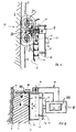
- Fig. 1 shows a side view of a sliding formwork, whose acting as a support surface Sliding surface 5, as basically described in DE-C1-35 33 476, there Fig. 6, with the Progress of a layer 1 to be sprayed on in the processing direction 17 according to the Arrow is movable. This movement is advantageously carried out continuously.
- the device for spraying one consists of a capable of setting curable mixture of binder additive and liquid existing Layer 1 on a wall 2, like that of a tunnel, the one to be sprayed on Mixing leading flexible pressure line 3, from whose on the wall 2nd directed and movable at a distance over the wall 2 end 4, the appropriate is formed by a spray nozzle 20, which exits the mixture to be sprayed and onto which Wall 2 arrives.
- the sliding surface 5 In one corresponding to the thickness of the layer 1 to be sprayed on Distance from the wall 2 is the sliding surface 5 forming the support surface according to Art a formwork is provided for the layer 1 to be sprayed on, the sliding surface 5 as mentioned, following the movements of the outlet end 4 of the pressure line 3 is movably arranged.
- the sliding surface 5 is supported by a support structure 13 and has a movement drive 8 to the sliding surface 5 according to the Movement of the outlet end 4 of the pressure line 3 the basic course of the Wall 2 still to lead, approximately along one in Fig. 1 by a two-dot chain line marked guide frame 23 (see. Fig. 5).
- the Movement drive 8 also in a manner not shown via pivotable arms of an independent drive device, e.g.
- the sliding surface 5 has one Support structure 13, which is associated with the motion drive 8 in a suitable manner.
- the support structure 13 can be connected to the pressure line 3 or the spray nozzle 20 be arranged mechanically coupled and on a common sprayer to be appropriate. It is also a movable attachment to the breakout profiles or on the wall 2 conceivable.
- the support structure 13 in essentially of a connection carrier 15 and one connected to the latter Support arm 16.
- the sliding surface 5 is on adapted to the wall curvatures and can have a leading surface at the front end 18 exhibit.
- the width and / or the length of the sliding surface 5 results from the practical conditions and is particularly adapted to the mixture used.
- a schematically represented reinforcement 22 can also be inserted into the manufactured layer 1 be inserted.
- the sliding surface 5 carries a schematic on its side facing away from the wall 2 Shown vibration element 6, which is in the area of the freshly applied mixture layer 1 mechanically high-frequency vibrations in the order of magnitude up to to 9000 Hz in the sinking direction, i.e. in the longitudinal direction of the tunnel corresponding to the Double arrow 36 in Fig. 5 exercises.
- vibration element 6 which is in the area of the freshly applied mixture layer 1 mechanically high-frequency vibrations in the order of magnitude up to to 9000 Hz in the sinking direction, i.e. in the longitudinal direction of the tunnel corresponding to the Double arrow 36 in Fig. 5 exercises.
- the support structure 13 has a support plate 14 which via support bracket 12 with the side of the sliding surface 5 facing away from the wall 2 is connected, with the vibration element 6 also in the space thus formed is provided.
- the support plate 14 is resilient via a schematically shown flexible suspension 19 with the connection carrier 15 of the supporting structure 13 connected. This creates a constant pressure against the outside pointing surface 9 of the layer 1 exercised and on the other hand safely avoided that the mechanical vibrations triggered by the vibration element 6 on the overlap other construction elements of the spraying device.
- FIG. 2 differs from that of FIG. 1 in essentially by a multi-unit design of the sliding surface 5.
- the front element 24 of the sliding surface 5 has the vibration element 6.
- Die different members 24 and 25 of the sliding surface 5 are associated with resilient flexible applications 27 and 28 connected to the connection carrier 15. By appropriate adjustment of the respective distance between these resilient suspensions 27, 28, an individual curvature of the entire sliding surface 5 can be adapted achieve the course of the wall 2.
- Fig. 3 shows a side view of a first embodiment of a sliding formwork, such as 1, with a lateral support device 30, which is used as side formwork works.
- this lateral support device 30 consists of a rotatable mounted disc 31, which resiliently on a resilient support 35 mounted pendulum arm 33 is attached, the spring-loaded pendulum arm 33 on the Support structure 13 is mounted.
- the pendulum arm 33 By this pendulum arm 33, the disc 31 is on pressed the wall 2 that it rolls along the wall 2 and the Unevenness of the wall 2 can follow.
- the side Support device as shown in Fig. 3, have a side sliding formwork 32.
- the Sliding formwork can be particularly advantageous when lining tunnel walls be used.
- the sliding formwork moves in a circular or spiral manner around the tunnel wall. While applying the first layer to each of the Both sides of the sliding formwork should be fitted with a side formwork Application of each subsequent layer adjacent to the first-mentioned layer lateral escape of the applied mixture through the already applied adjacent layer prevented on one side, so that for the second and each additional layer Such side formwork is only to be provided on one side of the sliding formwork.
- FIG. 4 shows another embodiment of a lateral support device 30.
- Two overlapping disks 31 1 and 31 2 are connected to a telescopic arm 34 directly or via a pendulum arm 33.
- This arrangement of telescopic arm 34 and / or pendulum arm 33 brings about an elastic pressing of the disks 31 1 and 31 2 against the wall 2.
- an additional sliding formwork such as the sliding formwork 32 in FIG. 3, can be dispensed with. It is conceivable to arrange further disks overlapping and / or entangled one behind the other in order to increase the effective length of the lateral support device 30.
- the elastically mounted disks 31 or 31 1 and 31 2 have the advantage of being able to roll over them and, by reaching into the fields of the reinforcement mats, the gap between them and the wall 2 nevertheless to be able to close largely.
- the sliding formwork can be along a guide frame 23 be performed.
- the Guide frame 23 advantageously designed according to the tunnel profile.
- a side surface 11 (FIG. 5) is formed from the mixture.
- the side support 30 does not necessarily have to be attached to the supporting structure 13 in the area of the connecting support 15, but can also in the region of the guide frame 23 with the support structure 13 be connected via a telescopic arm 34.
- the latter arrangement allows a special one simple retrofitting if the side surface 11 of layer 1 is not as in FIG. 5 shown above, but below (when shown in Fig. 5) should be provided.
- the desired uniform surface 9 free of tearing of the set Layer 1 can therefore be achieved.
Abstract
Description
Die Erfindung betrifft eine während des Aufbringens einer abbindefähigen Schicht
entlang der Verarbeitungsrichtung gleitend bewegbare Schalung, wie sie z.B. bei
Betonierarbeiten, insbesondere an Tunnelwandungen, eingesetzt wird.
Ein derartige, dem Oberbegriff des Anspruchs 1 entsprechende Gleitschalung
ist aus der EP-A-0 215 243 oder DE-C-3 533 476 der gleicher Anmelderin bekannt.The invention relates to a layer capable of setting during the application
Formwork slidably movable along the processing direction, e.g. at
Concreting work, especially on tunnel walls, is used.
Such a sliding formwork corresponding to the preamble of
Dort wird eine Vorrichtung zum Aufspritzen einer abbindefähigen Mischung aus Bindemittel-Zusatzstoff und einer Flüssigkeit offenbart. Die aufzubringende Mischung wird mittels einer auf die Wandung gerichteten Spritzdüse auf die Wandung aufgespritzt. Bis zum Eintritt einer selbsttragenden Verfestigung der Mischung während der Abbindevorganges ist es notwendig, die aufgespritzte Schicht durch eine Verschalung zu stützen. Dabei ist es vorteilhaft, die Verschalung entlang der Verarbeitungsrichtung mit konstanter langsamer Vorschubgeschwindigkeit mitzuführen, wodurch ein zeitraubendes Anbringen einer ortsfesten Verschalung und deren Wiederentfernung vermieden wird. Hierzu eignet sich insbesondere die dort beschriebene Rollschalung, die nach Art und Weise eines Raupenfahrzeuges über die aufgespritzte Mischung bewegt wird. Dabei ist zwischen zwei walzenartigen Umlenkelementen im Bereich der Oberfläche der zu stützenden Schicht eine Schalhaut gespannt, die gegebenenfalls unter Zusammenwirken mit einer an der Unterseite der Schalhaut angeordneten Stützplatte in der Lage ist, die aufgespritzte Schicht ausreichend zu stützen. Gemäß einer vereinfachten Ausführungsform wird statt einer solchen um Umlenkelemente geführten Schalhaut eine schalungsähnliche Stützfläche verwendet, die gleitend über die aufgespritzte Mischung bewegt wird. Diese Gleitschalung hat insofern Vorteile, als deren konstruktiver Aufbau gegenüber der Rollschalung wesentlich vereinfacht ist.There is a device for spraying a setting capable Mixture of binder additive and a liquid disclosed. The The mixture to be applied is sprayed onto the wall by means of a spray nozzle sprayed on the wall. Until a self-supporting consolidation of the Mixing during the setting process it is necessary to spray the layer supported by a formwork. It is advantageous to formwork along the Carry processing direction with constant slow feed speed, whereby a time-consuming installation of a fixed formwork and its Removal is avoided. The one there is particularly suitable for this Roll formwork described, which in the manner of a crawler vehicle over the sprayed mixture is moved. It is between two roller-like A formwork skin in the area of the surface of the layer to be supported looking forward to interacting with one at the bottom of the Formwork skin arranged support plate is able to cover the sprayed layer sufficiently to support. According to a simplified embodiment, instead of such Deflection-guided formwork skin uses a formwork-like support surface that is slid over the sprayed mixture. In this respect, this sliding formwork has Advantages, as their structural design compared to the roll formwork essential is simplified.
Es hat sich im Betrieb nun jedoch gezeigt, daß durch das intermittierend erfolgende Aufspritzen der Mischung die Mischung teilweise an der Gleitschalung haften bleiben kann. Da jedoch die Schalung kontinuierlich weitergeführt wird, wird der haftenbleibende Teil der Mischung mitgenommen und wird die Oberfläche der Schicht aufgerissen. Selbst durch den Spritzdruck des nachfolgend aufgespritzten Teils der Mischung kann dies nicht immer rückgängig gemacht werden. Somit ist die Sichtfläche der so gebildeten Schicht optisch unbefriedigend, in der Praxis muß nachgearbeitet, nämlich abgestrichen werden, wobei dies per Hand erfolgen muß. Dies ist nicht nur unbequem und zeitraubend, sondern auch kostspielig.It has now been shown in operation, however, that due to the intermittent When the mixture is sprayed on, the mixture partially sticks to the sliding formwork can. However, since the formwork is continued, the sticky part of the mixture and the surface of the layer torn open. Even by the spray pressure of the subsequently sprayed on part of the Mix this cannot always be undone. So the visible area the layer thus formed is optically unsatisfactory, in practice it has to be reworked, namely to be smeared, which must be done by hand. This is not just inconvenient and time consuming, but also costly.
Es ist zu bemerken, daß dieser Nachteil grundsätzlich auch bei einer Rollschalung auftreten kann.It should be noted that this disadvantage also applies to roller formwork can occur.
Es ist daher Aufgabe der Erfindung, die Gleitschalung der eingangs genannten Art so weiterzubilden, daß die Mitnahme von an der Stützfläche anhaftender Mischung vermieden wird.It is therefore an object of the invention, the slipform of the type mentioned to further develop the entrainment of the mixture adhering to the support surface is avoided.
Die Aufgabe wird erfindungsgemäß dadurch gelöst, daß das Vibrationselement eine Schwingung in Abteufrichtung der Wandung, insbesondere Tunnellängsrichtung, ausübt, so daß die Mitnahme von an der Stützfläche anhaftender Mischung vermieden wird.The object is achieved in that the vibration element is an oscillation in the direction of sinking of the wall, in particular tunnel longitudinal direction, so that the entrainment of mixture adhering to the support surface is avoided.
Insbesondere soll eine hochfrequente mechanische Schwingung in Abteufrichtung, d.h. in Längsrichtung eines Tunnels, ausgeübt werden. Hierdurch wird weniger eine Verdichtungswirkung der in der Praxis schnell aushärtenden Mischung der zu bildenden Schicht bewirkt, vielmehr wird kontinuierlich eine eine etwaige Haftung lösende Wirkung ausgelöst.In particular, a high-frequency mechanical vibration in the sinking direction, i.e. in the longitudinal direction of a tunnel. This makes less one Compaction effect of the mixture of the mixture to be formed which hardens in practice Layer causes, rather a continuously loosening any adhesion Effect triggered.
Die erfindungsgemäße Lösung der Aufgabe hat demnach nichts mit dem bekannten Rütteln von Beton-Mischungen zwecks deren Verdichtung zu tun, wie dies an sich bekannt ist und auch in Zusammenhang mit der Rollschalung, und zwar ausdrücklich zu Verdichtungszwecken, beschrieben worden ist.The solution of the task according to the invention therefore has nothing to do with the known Shake concrete mixes in order to compact them to do this as such is known and also in connection with the roller shuttering, specifically to Compaction purposes has been described.
Vorteilhaft kann die Gleitschalung mit einer seitlichen Stützvorrichtung gemäß Anspruch 4 versehen sein, um zu verhindern, daß die aufgebrachte abbindefähige Mischung nach dem Aufbringen und vor einer wesentlichen Verfestigung seitlich entweichen kann. Die seitliche Stützvorrichtung ist daher zweckmäßig flexibel gelagert und mittels einer Andrückvorrichtung, z.B. einer Feder, elastisch an die Wandung andrückbar. Vorteilhaft kann diese seitliche Stützvorrichtung ebenfalls mit einem Vibrationselement versehen sein, das in Richtung auf die Wandung zu bzw. von dieser weg wirkt, also in Radialrichtung eines Tunnels.The sliding formwork can advantageously be provided with a lateral support device Claim 4 be provided to prevent the applied setable Mix after application and before substantial consolidation on the side can escape. The lateral support device is therefore suitably flexibly mounted and by means of a pressing device, e.g. a spring, elastic to the wall pressable. This lateral support device can also advantageously be equipped with a Be provided vibration element, in the direction of the wall to or from this acts away, i.e. in the radial direction of a tunnel.
Weitere vorteilhafte Weiterbildungen sind in den Unteransprüchen gekennzeichnet. Further advantageous developments are characterized in the subclaims.
Die Erfindung wird anhand der in der Zeichnung dargestellten Ausführungsbeispiele näher erläutert. Es zeigen:
- Fig. 1
- schematisch ein Ausführungsbeispiel einer Gleitschalung mit einem Vibrationselement gemäß der Erfindung;
- Fig. 2
- ähnlich Fig. 1 eine mehrgliedrige Ausbildung einer Gleitschalung;
- Fig. 3
- eine mit einer seitlichen Stützvorrichtung versehene Gleitschalung gemäß der Erfindung;
- Fig. 4
- eine andere Ausführungsform einer seitlichen Stützvorrichtung;
- Fig. 5
- eine weitere Ausführungsform der Halterung einer seitlichen Stützvorrichtung.
- Fig. 1
- schematically an embodiment of a sliding formwork with a vibration element according to the invention;
- Fig. 2
- similar to Figure 1, a multi-unit design of a sliding formwork.
- Fig. 3
- a slip form provided with a lateral support device according to the invention;
- Fig. 4
- another embodiment of a side support device;
- Fig. 5
- a further embodiment of the holder of a lateral support device.
Fig. 1 zeigt eine Seitenansicht einer Gleitschalung, deren als Stützfläche wirkende
Gleitfläche 5, wie grundsätzlich in DE-C1-35 33 476, dort Fig. 6, beschrieben mit dem
Fortschreiten einer aufzuspritzenden Schicht 1 in Verarbeitungsrichtung 17 gemäß dem
Pfeil weiterbewegbar ist. Diese Bewegung erfolgt zweckmäßig kontinuierlich.
Insgesamt besteht die Vorrichtung zum Aufspritzen einer aus einer abbindefähigen
erhärtbaren Mischung aus Bindemittel-Zuschlagstoff und Flüssigkeit bestehenden
Schicht 1 auf eine Wandung 2, wie der eines Tunnels, aus einer die aufzuspritzende
Mischung heranleitenden flexiblen Druckleitung 3, aus deren auf die Wandung 2
gerichteten und mit Abstand über die Wandung 2 bewegbaren Ende 4, das zweckmäßig
durch eine Spritzdüse 20 gebildet ist, die aufzuspritzende Mischung austritt und auf die
Wandung 2 gelangt. In einem der Dicke der aufzuspritzenden Schicht 1 entsprechenden
Abstand von der Wandung 2 ist die die Stützfläche bildende Gleitfläche 5 nach Art
einer Schalung für die aufzuspritzende Schicht 1 vorgesehen, wobei die Gleitfläche 5
wie erwähnt, den Bewegungen des Austrittsendes 4 der Druckleitung 3 folgend
bewegbar angeordnet ist. Die Gleitfläche 5 ist über eine Tragkonstruktion 13 gehaltert
und weist einen Bewegungsantrieb 8 auf, um die Gleitfläche 5 entsprechend der
Bewegung des Austrittsendes 4 der Druckleitung 3 dem grundsätzlichen Verlauf der
Wandung 2 noch zu führen, etwa längs einem in Fig. 1 durch eine Zweipunkt-Strich-Linie
gekennzeichneten Führungsrahmen 23 (vgl. Fig. 5). Jedoch kann der
Bewegungsantrieb 8 auch in nicht dargestellter Weise über schwenkbare Arme von
einem unabhängigen Antriebsgerät, z.B. einem Bagger oder dgl., geführt sein, wodurch
auf diese Weise die erwähnte Bewegung in Pfeilrichtung 17 erreicht wird. Auf den
örtlich vorgegebenen Flächenbereich 21 zwischen Wandung 2 bzw. Gebirge und
Gleitfläche 5 wird gespritzt, wodurch der Rückprall bei richtiger Einstellung des
Spritzwinkels, des Spritzdruckes und des Abstandes der Düse 20 von dem
Auftragsflächenbereich 21 auf ein Minimum reduziert wird. Die
Vortriebsgeschwindigkeit in Richtung des Pfeils 17 hängt dabei von der Spritzleistung
ab.Fig. 1 shows a side view of a sliding formwork, whose acting as a support
Bei dem dargestellten Ausführungsbeispiel besitzt die Gleitfläche 5 eine
Tragkonstruktion 13, die dem Bewegungsantrieb 8 in geeigneter Weise zugeordnet ist.
Dabei kann die Tragkonstruktion 13 mit der Druckleitung 3 bzw. mit der Spritzdüse 20
mechanisch gekoppelt angeordnet sein und an einem gemeinsamen Spritzgerät
angebracht sein. Es ist auch eine bewegbare Anbringung an den Ausbruchprofilen bzw.
an der Wandung 2 denkbar. Wie dargestellt, besteht die Tragkonstruktion 13 im
wesentlichen aus einem Verbindungsträger 15 und einem mit letzterem verbundenen
Tragarm 16. Zur Berücksichtigung gekrümmter Wandungen 2 ist die Gleitfläche 5 an
die Wandungskrümmungen angepaßt und kann am Vorderende eine Vorlauffläche 18
aufweisen. Die Breite und/oder die Länge der Gleitfläche 5 ergibt sich aus den
praktischen Gegebenheiten und ist insbesondere an die verwendete Mischung angepaßt.
In die gefertigte Schicht 1 kann ferner eine schematisch dargestellte Bewehrung 22
eingelegt sein.In the illustrated embodiment, the
Die Gleitfläche 5 trägt an ihrer der Wandung 2 abgewandten Seite ein schematisch
dargestelltes Vibrationselement 6, das im Bereich der frisch aufgebrachten Mischung
der Schicht 1 mechanisch hochfrequente Schwingungen in der Größenordnung von bis
zu 9000 Hz in Abteufrichtung, also in Tunnellängsrichtung entsprechend dem
Doppelpfeil 36 in Fig. 5 ausübt. Hierdurch wird keine an sich bekannte Rüttel- oder
Verdichtungswirkung der schnell abbindenden und damit schnell erstarrenden Mischung
der Schicht 1 bewirkt, sondern vielmehr ständig und kontinuierlich verhindert, daß an
der durch die Gleitfläche 5 gebildeten Gleitschalung Teile der eingespritzten Mischung
haften bleiben.The sliding
Wie schematisch dargestellt, weist die Tragkonstruktion 13 eine Stützplatte 14 auf, die
über Stützträger 12 fest mit der der Wandung 2 abgewandten Seite der Gleitfläche 5
verbunden ist, wobei in dem so gebildeten Raum auch das Vibrationselement 6
vorgesehen ist. Die Stützplatte 14 ist über eine schematisch dargestellte federnd
nachgiebige Aufhängung 19 mit dem Verbindungsträger 15 der Tragkonstruktion 13
verbunden. Hierdurch wird zum einen ein ständiger Druck gegen die nach außen
weisende Oberfläche 9 der Schicht 1 ausgeübt und andererseits sicher vermieden, daß
die durch das Vibrationselement 6 ausgelösten mechanischen Schwingungen auf die
übrigen Konstruktionselemente der Spritzvorrichtung übergreifen.As shown schematically, the
Das Ausführungsbeispiel gemäß Fig. 2 unterscheidet sich von dem gemäß Fig. 1 im
wesentlichen durch eine mehrgliedrige Ausbildung der Gleitfläche 5. Insbesondere sind
mehrere Glieder 24 und 25 in Vorschubrichtung der Gleitfläche 5, also in Richtung des
Pfeils 17 hintereinander angeordnet und miteinander über nur schematisch dargestellte
Verbindungselemente 26 gekoppelt. Zumindest das in Vorschubrichtung (Pfeil 17)
vorne liegende Glied 24 der Gleitfläche 5 weist das Vibrationselement 6 auf. Die hinten
liegenden übrigen Glieder 25, in deren Bereich eine gewisse Verfestigung der Mischung
der Schicht 1 bereits stattgefunden hat, benötigen das Vibrationselement 6 nicht mehr
und dienen vielmehr zum Abstreichen, d.h. zur Endausbildung der Oberfläche 9. Die
verschiedenen Glieder 24 und 25 der Gleitfläche 5 sind über zugeordnete federnd
nachgiebige Aufbringungen 27 bzw. 28 mit dem Verbindungsträger 15 verbunden.
Durch geeignete Einstellung des jeweiligen Abstandes dieser federnden Aufhängungen
27, 28 läßt sich eine individuelle Krümmung der gesamten Gleitfläche 5 zur Anpassung
an den Verlauf der Wandung 2 erzielen.The embodiment of FIG. 2 differs from that of FIG. 1 in
essentially by a multi-unit design of the sliding
Fig. 3 zeigt eine Seitenansicht einer ersten Ausführungsform einer Gleitschalung, wie
etwa gemäß Fig. 1, mit einer seitlichen Stützvorrichtung 30, die als Seitenschalung
wirkt. Gemäß Fig. 3 besteht diese seitliche Stützvorrichtung 30 aus einer drehbar
gelagerten Scheibe 31, die an einem über eine federnde Abstützung 35 federnd
gelagerten Pendelarm 33 befestigt ist, wobei der federnd gelagerte Pendelarm 33 an der
Tragkonstruktion 13 gelagert ist. Durch diesen Pendelarm 33 wird die Scheibe 31 so an
die Wandung 2 angedrückt, daß diese an der Wandung 2 entlang rollt und dabei den
Unebenheiten der Wandung 2 zu folgen vermag. Zusätzlich kann die seitliche
Stützvorrichtung, wie in Fig. 3 dargestellt, eine Seiten-Gleitschalung 32 aufweisen.Fig. 3 shows a side view of a first embodiment of a sliding formwork, such as
1, with a
Während des Vorschubes der Gleitschalung härtet die abbindefähige Mischung soweit aus, daß sie am hinteren Ende der Gleitschalung selbsttragend verfestigt ist. Die Gleitschalung kann insbesondere bei der Auskleidung von Tunnelwandungen vorteilhaft eingesetzt werden. Die Gleitschalung bewegt sich dabei kreisförmig oder spiralförmig um die Tunnelwandung. Während beim Aufbringen der ersten Schicht an jeder der beiden Seiten der Gleitschalung eine Seitenschalung angebracht sein sollte, wird beim Aufbringen jeder folgenden an die erstgenannte Schicht angrenzenden Schicht das seitliche Entweichen der aufgebrachten Mischung durch die bereits aufgebrachte angrenzende Schicht einseitig verhindert, so daß für die zweite und jede weitere Schicht nur an einer Seite der Gleitschalung eine solche Seitenschalung vorzusehen ist.As the formwork advances, the ready-to-set mixture hardens from that it is self-supporting solidified at the rear end of the sliding formwork. The Sliding formwork can be particularly advantageous when lining tunnel walls be used. The sliding formwork moves in a circular or spiral manner around the tunnel wall. While applying the first layer to each of the Both sides of the sliding formwork should be fitted with a side formwork Application of each subsequent layer adjacent to the first-mentioned layer lateral escape of the applied mixture through the already applied adjacent layer prevented on one side, so that for the second and each additional layer Such side formwork is only to be provided on one side of the sliding formwork.
Fig. 4 zeigt eine andere Ausführungsform einer seitlichen Stützvorrichtung 30. Es sind
zwei überlappend angeordnete Scheiben 311 und 312 unmittelbar oder über je einen
Pendelarm 33 mit einem Teleskoparm 34 verbunden. Diese Anordnung aus
Teleskoparm 34 und/oder Pendelarm 33 bewirkt dabei ein elastisches Andrücken der
Scheiben 311 und 312 an die Wandung 2. Hierbei kann auf eine zusätzliche
Gleitschalung, wie die Gleitschalung 32 in Fig. 3, verzichtet werden. Es ist denkbar,
weitere Scheiben überlappend und/oder verschränkt hintereinander anzuordnen, um die
effektive Länge der seitlichen Stützvorrichtung 30 zu vergrößern. Falls in der
aufzubringenden Schicht 1 Bewehrungsmatten 22 vorgesehen sind, weisen die elastisch
gelagerten Scheiben 31 bzw. 311 und 312 den Vorteil auf, diese überrollen zu können
und durch das Hineinreichen in die Felder der Bewehrungsmatten den Spalt zwischen
diesen und der Wandung 2 dennoch weitgehend schließen zu können.4 shows another embodiment of a
Wie aus Fig. 5 ersichtlich, kann die Gleitschalung entlang eines Führungsrahmens 23
geführt werden. Bei Verwendung bei der Auskleidung eines Tunnels ist der
Führungsrahmen 23 vorteilhaft entsprechend dem Tunnelprofil ausgebildet.As can be seen from FIG. 5, the sliding formwork can be along a
Durch das durch die seitliche Stützvorrichtung 30 verhinderte Austreten aufgebrachter Mischung wird eine Seitenfläche 11 (Fig. 5) gebildet.More exasperated by the leakage prevented by the lateral support device 30 A side surface 11 (FIG. 5) is formed from the mixture.
Wie in Fig. 5 dargestellt, muß die seitliche Stützvorrichtung 30 nicht notwendigerweise
im Bereich des Verbindungsträgers 15 an der Tragkonstruktion 13 angebracht sein,
sondern kann auch im Bereich des Führungsrahmens 23 mit der Tragkonstruktion 13
über einen Teleskoparm 34 verbunden sein. Letztere Anordnung erlaubt eine besonders
einfache Umrüstung, falls die Seitenfläche 11 der Schicht 1 nicht wie in Fig. 5
dargestellt, oben, sondern unten (bei Darstellung in Fig. 5) vorgesehen sein soll.As shown in Fig. 5, the
Von besonderem Vorteil ist es, wenn auch bei der seitlichen Stützvorrichtung 30 das
Anhaften von eingespritzter Mischung der Schicht 1 verhindern wird. Dies kann in
Weiterbildung des Gedankens der vorliegenden Erfindung dadurch erfolgen, daß auch
der seitlichen Stützvorrichtung 30 ein Vibrationselement 7 (vgl. Fig. 3,4 und 5)
zugeordnet ist, die eine Schwingungsbewegung der Seitenschalung in Radialrichtung
bewirkt, also in Richtung des Doppelpfeils 37 auf die Wandung 2 zu und von dieser
weg. Auch hier ist eine Verdichtungswirkung, so sie überhaupt erreicht ist, nicht
angestrebt, vielmehr wird kontinuierlich eine haftungslösende Wirkung, also eine
Anhaftung von Mischung verhindernde Wirkung erzielt.It is particularly advantageous if this also applies to the
Erste Untersuchungen haben ergeben, daß die erfindungsgemäße Anordnung tatsächlich
das Anhaften von Mischung an der Gleitfläche 5 wirksam vermeiden kann, so daß auf
kostspieliges Nacharbeiten verzichtet werden kann.Initial investigations have shown that the arrangement according to the invention actually
can effectively avoid the sticking of mixture on the sliding
Die erwünschte gleichmäßige von Aufrissen freie Oberfläche 9 der abgebundenen
Schicht 1 kann also erzielt werden.The desired
Claims (12)
- Support device for the support of a layer (1), of a settable mixture and applied to a wall (2), in a condition of the mixture which is not yet self-supportingly set,
having a sliding surface (5), connected with a carrier construction (13), which in the range of its surface extent offers a shuttering-like support surface, whereby there is connected with the sliding surface (5), away from the wall (2), at least one vibration element (6) that has effect on the applied layer (1) via the slide surface (5),
characterised in that,
the vibration element (6) exercises an oscillation in the direction of sinking of the wall (2), in particular the tunnel longitudinal direction, so that the carrying along of mixture adhering to the support surface is avoided. - Support device according to claim 1,
characterised in that,
the vibration element (6) achieves high frequency mechanical oscillations of the sliding surface (5). - Support device according to claim 2,
characterised by frequencies of the order of up to 9000 Hz. - Support device according to any of claims 1 to 3,
characterised by a flexibly mounted shuttering-like lateral support device (30) which supports the settable mixture at least in the region of a sideline of the sliding surface (5) between the wall (2) and the sliding surface, if appropriate with a pressing device (35) which presses the lateral support device (30) against the wall, elastically following the
unevennesses of the wall (2), so that the region between the sliding surface (5) and the wall (2) along the at least one sideline of the sliding surface (5) is in substance completely closed. - Support device according to claim 4,
characterised in that,
a further vibration element (7) acts on the lateral support device (30) independently of the sliding surface (5). - Support device according to claim 4 or 5,
characterised in that,
the further vibration element (7) exercises an oscillation in a direction towards the wall (2). - Support device according to any of claims 4 or 6,
characterised in that,
the lateral support device (30) is formed by means of one or more rotatable disks (31; 311, 312), which roll along the wall (2). - Support device according to 7,
characterised in that,
there are provided a plurality of disks (311, 312) arranged overlapping and/or crossing. - Support device according to any of claims 4 or 8,
characterised in that,
the lateral support device (30) is attached to the carrier construction (13) by means of sprung telescopic and/or pendulum arms (34, 33). - Support device according to any of claims 1 to 9,
characterised by a multiple member construction of the sliding surface (5), whereby the members (24, 25) follow one another in the direction of application of the layer (1). - Support device according to claim 10,
characterised in that,
the vibration element (6) is associated with at least that member (24) of the sliding surface (5) which is forwardmost in the direction of application of the layer (1). - Device according to any of claims 1 to 11,
characterised in that,
the vibration element (6) is mounted on the sliding surface (5) which is supported in a sprung yielding (19) manner against the carrier construction (13).
Applications Claiming Priority (2)
| Application Number | Priority Date | Filing Date | Title |
|---|---|---|---|
| DE4411976 | 1994-04-07 | ||
| DE4411976A DE4411976A1 (en) | 1994-04-07 | 1994-04-07 | Sliding formwork |
Publications (2)
| Publication Number | Publication Date |
|---|---|
| EP0676531A1 EP0676531A1 (en) | 1995-10-11 |
| EP0676531B1 true EP0676531B1 (en) | 1999-10-13 |
Family
ID=6514821
Family Applications (1)
| Application Number | Title | Priority Date | Filing Date |
|---|---|---|---|
| EP95102979A Expired - Lifetime EP0676531B1 (en) | 1994-04-07 | 1995-03-02 | Slip-form casting for tunnel walls |
Country Status (3)
| Country | Link |
|---|---|
| EP (1) | EP0676531B1 (en) |
| AT (1) | ATE185609T1 (en) |
| DE (2) | DE4411976A1 (en) |
Families Citing this family (4)
| Publication number | Priority date | Publication date | Assignee | Title |
|---|---|---|---|---|
| AT504264B1 (en) * | 2006-07-25 | 2012-07-15 | Porr Tunnelbau Gmbh | DEVICE AND METHOD FOR APPLYING AN ADJUSTABLE LAYER TO WALLS OF COMPONENTS |
| CN109538250B (en) * | 2019-01-28 | 2023-09-15 | 中南大学 | Device and method for quick construction of tunnel primary support with mould sprayed concrete |
| CN114320364A (en) * | 2021-12-21 | 2022-04-12 | 洛阳中铁强力机械有限公司 | Tunnel spouts anchor auxiliary trolley |
| CN114294020A (en) * | 2021-12-31 | 2022-04-08 | 北京市政建设集团有限责任公司 | Side guide hole backfill construction method |
Family Cites Families (4)
| Publication number | Priority date | Publication date | Assignee | Title |
|---|---|---|---|---|
| CH613015A5 (en) * | 1976-07-15 | 1979-08-31 | Spribag Ag | Mobile apparatus for applying shotcrete to walls |
| DE3037790A1 (en) * | 1980-10-07 | 1982-05-13 | Gewerkschaft Eisenhütte Westfalia, 4670 Lünen | Underground gallery or tunnel lining sprayed concrete appliance - has sliding plate on feed duct movably edging into form space against concrete end |
| DE3533476C1 (en) * | 1985-09-19 | 1986-06-12 | Philipp Holzmann Ag, 6000 Frankfurt | Device for spraying a layer capable of setting onto walls |
| DE4316116A1 (en) * | 1993-05-13 | 1994-11-17 | Holzmann Philipp Ag | Roll formwork |
-
1994
- 1994-04-07 DE DE4411976A patent/DE4411976A1/en not_active Ceased
-
1995
- 1995-03-02 EP EP95102979A patent/EP0676531B1/en not_active Expired - Lifetime
- 1995-03-02 AT AT95102979T patent/ATE185609T1/en not_active IP Right Cessation
- 1995-03-02 DE DE59507017T patent/DE59507017D1/en not_active Expired - Fee Related
Also Published As
| Publication number | Publication date |
|---|---|
| ATE185609T1 (en) | 1999-10-15 |
| DE59507017D1 (en) | 1999-11-18 |
| DE4411976A1 (en) | 1995-10-12 |
| EP0676531A1 (en) | 1995-10-11 |
Similar Documents
| Publication | Publication Date | Title |
|---|---|---|
| DE2624212C2 (en) | Mobile machine for continuously leveling and compacting the ballast bedding of a track | |
| EP0676531B1 (en) | Slip-form casting for tunnel walls | |
| DE3533476C1 (en) | Device for spraying a layer capable of setting onto walls | |
| DE2803673C2 (en) | Mobile ramming device for applying lining material to casting channels in blast furnaces | |
| CH677076A5 (en) | ||
| DE2610519C2 (en) | Track tamping machine | |
| DE2612169C3 (en) | Control device for a knife shield | |
| DE4403243A1 (en) | Spray gun for liq. bitumen or other binders | |
| DE2556547B2 (en) | Verge paver | |
| DE3037790C2 (en) | ||
| DE4014098C2 (en) | ||
| EP0022121A1 (en) | Supporting and guiding frame for continuous casting plants | |
| EP0728241B1 (en) | Mechanism for directly or indirectly applying a liquid or pasty medium onto a moving strip of material | |
| EP0624713B1 (en) | Rollshuttering | |
| DE3132870A1 (en) | TRACK LEVELING PLUG AND LEVELING MACHINE WITH STABILIZATION UNIT | |
| DE2621421C2 (en) | Torque support for a propulsion shield | |
| DE2439788A1 (en) | Self-propelled tarmac-consolidating road-roller - with separately line-adjustable roller units independently controllable for movement and vibration | |
| DE2754103C3 (en) | Device provided on a rail vehicle for distributing and profiling the ballast ballast of a track | |
| DE3129060A1 (en) | METHOD AND DUCT LENGTH MACHINE FOR INSTALLING LININGS IN WATER CHANNELS, E.g. IN IRRIGATION CHANNELS | |
| DE2727932B1 (en) | Device for stepless adjustment of the working widths of road pavers | |
| DE2949005C2 (en) | ||
| AT412735B (en) | DEVICE FOR APPLYING A BINDING AGENT FOR AN ASPHALT BEARING ON A TRAFFIC SURFACE | |
| DE1206383B (en) | Stepping suspension or fixing device (bracing) for the end station of a conveyor, especially in planing struts | |
| DE2633321A1 (en) | DUMP OF A PAPER MACHINE | |
| DE2520915C3 (en) | Shoring shield for tunnel or gallery driving and the like and method for its use |
Legal Events
| Date | Code | Title | Description |
|---|---|---|---|
| PUAI | Public reference made under article 153(3) epc to a published international application that has entered the european phase |
Free format text: ORIGINAL CODE: 0009012 |
|
| AK | Designated contracting states |
Kind code of ref document: A1 Designated state(s): AT BE CH DE DK ES FR GB GR IE IT LI LU MC NL PT SE |
|
| 17P | Request for examination filed |
Effective date: 19960206 |
|
| GRAG | Despatch of communication of intention to grant |
Free format text: ORIGINAL CODE: EPIDOS AGRA |
|
| 17Q | First examination report despatched |
Effective date: 19981211 |
|
| GRAG | Despatch of communication of intention to grant |
Free format text: ORIGINAL CODE: EPIDOS AGRA |
|
| GRAH | Despatch of communication of intention to grant a patent |
Free format text: ORIGINAL CODE: EPIDOS IGRA |
|
| GRAH | Despatch of communication of intention to grant a patent |
Free format text: ORIGINAL CODE: EPIDOS IGRA |
|
| GRAA | (expected) grant |
Free format text: ORIGINAL CODE: 0009210 |
|
| AK | Designated contracting states |
Kind code of ref document: B1 Designated state(s): AT BE CH DE DK ES FR GB GR IE IT LI LU MC NL PT SE |
|
| PG25 | Lapsed in a contracting state [announced via postgrant information from national office to epo] |
Ref country code: SE Free format text: THE PATENT HAS BEEN ANNULLED BY A DECISION OF A NATIONAL AUTHORITY Effective date: 19991013 Ref country code: NL Free format text: LAPSE BECAUSE OF FAILURE TO SUBMIT A TRANSLATION OF THE DESCRIPTION OR TO PAY THE FEE WITHIN THE PRESCRIBED TIME-LIMIT Effective date: 19991013 Ref country code: IT Free format text: LAPSE BECAUSE OF FAILURE TO SUBMIT A TRANSLATION OF THE DESCRIPTION OR TO PAY THE FEE WITHIN THE PRESCRIBED TIME-LIMIT;WARNING: LAPSES OF ITALIAN PATENTS WITH EFFECTIVE DATE BEFORE 2007 MAY HAVE OCCURRED AT ANY TIME BEFORE 2007. THE CORRECT EFFECTIVE DATE MAY BE DIFFERENT FROM THE ONE RECORDED. Effective date: 19991013 Ref country code: GR Free format text: LAPSE BECAUSE OF NON-PAYMENT OF DUE FEES Effective date: 19991013 Ref country code: GB Free format text: LAPSE BECAUSE OF FAILURE TO SUBMIT A TRANSLATION OF THE DESCRIPTION OR TO PAY THE FEE WITHIN THE PRESCRIBED TIME-LIMIT Effective date: 19991013 Ref country code: FR Free format text: LAPSE BECAUSE OF FAILURE TO SUBMIT A TRANSLATION OF THE DESCRIPTION OR TO PAY THE FEE WITHIN THE PRESCRIBED TIME-LIMIT Effective date: 19991013 Ref country code: ES Free format text: THE PATENT HAS BEEN ANNULLED BY A DECISION OF A NATIONAL AUTHORITY Effective date: 19991013 |
|
| REF | Corresponds to: |
Ref document number: 185609 Country of ref document: AT Date of ref document: 19991015 Kind code of ref document: T |
|
| REG | Reference to a national code |
Ref country code: CH Ref legal event code: EP |
|
| REF | Corresponds to: |
Ref document number: 59507017 Country of ref document: DE Date of ref document: 19991118 |
|
| PG25 | Lapsed in a contracting state [announced via postgrant information from national office to epo] |
Ref country code: PT Free format text: LAPSE BECAUSE OF FAILURE TO SUBMIT A TRANSLATION OF THE DESCRIPTION OR TO PAY THE FEE WITHIN THE PRESCRIBED TIME-LIMIT Effective date: 20000113 Ref country code: DK Free format text: LAPSE BECAUSE OF FAILURE TO SUBMIT A TRANSLATION OF THE DESCRIPTION OR TO PAY THE FEE WITHIN THE PRESCRIBED TIME-LIMIT Effective date: 20000113 |
|
| REG | Reference to a national code |
Ref country code: IE Ref legal event code: FG4D Free format text: GERMAN |
|
| PG25 | Lapsed in a contracting state [announced via postgrant information from national office to epo] |
Ref country code: LU Free format text: LAPSE BECAUSE OF NON-PAYMENT OF DUE FEES Effective date: 20000302 Ref country code: AT Free format text: LAPSE BECAUSE OF NON-PAYMENT OF DUE FEES Effective date: 20000302 |
|
| EN | Fr: translation not filed | ||
| PG25 | Lapsed in a contracting state [announced via postgrant information from national office to epo] |
Ref country code: LI Free format text: LAPSE BECAUSE OF NON-PAYMENT OF DUE FEES Effective date: 20000331 Ref country code: CH Free format text: LAPSE BECAUSE OF NON-PAYMENT OF DUE FEES Effective date: 20000331 Ref country code: BE Free format text: LAPSE BECAUSE OF NON-PAYMENT OF DUE FEES Effective date: 20000331 |
|
| NLV1 | Nl: lapsed or annulled due to failure to fulfill the requirements of art. 29p and 29m of the patents act | ||
| GBV | Gb: ep patent (uk) treated as always having been void in accordance with gb section 77(7)/1977 [no translation filed] |
Effective date: 19991013 |
|
| PG25 | Lapsed in a contracting state [announced via postgrant information from national office to epo] |
Ref country code: IE Free format text: LAPSE BECAUSE OF NON-PAYMENT OF DUE FEES Effective date: 20000621 |
|
| REG | Reference to a national code |
Ref country code: IE Ref legal event code: FD4D |
|
| PLBE | No opposition filed within time limit |
Free format text: ORIGINAL CODE: 0009261 |
|
| STAA | Information on the status of an ep patent application or granted ep patent |
Free format text: STATUS: NO OPPOSITION FILED WITHIN TIME LIMIT |
|
| 26N | No opposition filed | ||
| BERE | Be: lapsed |
Owner name: PHILIPP HOLZMANN A.G. Effective date: 20000331 |
|
| PG25 | Lapsed in a contracting state [announced via postgrant information from national office to epo] |
Ref country code: MC Free format text: LAPSE BECAUSE OF NON-PAYMENT OF DUE FEES Effective date: 20000930 |
|
| REG | Reference to a national code |
Ref country code: CH Ref legal event code: PL |
|
| PGFP | Annual fee paid to national office [announced via postgrant information from national office to epo] |
Ref country code: DE Payment date: 20020222 Year of fee payment: 8 |
|
| PG25 | Lapsed in a contracting state [announced via postgrant information from national office to epo] |
Ref country code: DE Free format text: LAPSE BECAUSE OF NON-PAYMENT OF DUE FEES Effective date: 20051124 |