EP0676367B1 - Safety device for a pump to be installed in pipes for liquids, water in particular, and device for feeding liquid - Google Patents
Safety device for a pump to be installed in pipes for liquids, water in particular, and device for feeding liquid Download PDFInfo
- Publication number
- EP0676367B1 EP0676367B1 EP95105063A EP95105063A EP0676367B1 EP 0676367 B1 EP0676367 B1 EP 0676367B1 EP 95105063 A EP95105063 A EP 95105063A EP 95105063 A EP95105063 A EP 95105063A EP 0676367 B1 EP0676367 B1 EP 0676367B1
- Authority
- EP
- European Patent Office
- Prior art keywords
- pump
- safety device
- probe
- housing
- fluid
- Prior art date
- Legal status (The legal status is an assumption and is not a legal conclusion. Google has not performed a legal analysis and makes no representation as to the accuracy of the status listed.)
- Expired - Lifetime
Links
Images
Classifications
-
- B—PERFORMING OPERATIONS; TRANSPORTING
- B67—OPENING, CLOSING OR CLEANING BOTTLES, JARS OR SIMILAR CONTAINERS; LIQUID HANDLING
- B67D—DISPENSING, DELIVERING OR TRANSFERRING LIQUIDS, NOT OTHERWISE PROVIDED FOR
- B67D1/00—Apparatus or devices for dispensing beverages on draught
- B67D1/08—Details
- B67D1/12—Flow or pressure control devices or systems, e.g. valves, gas pressure control, level control in storage containers
- B67D1/1202—Flow control, e.g. for controlling total amount or mixture ratio of liquids to be dispensed
- B67D1/1234—Flow control, e.g. for controlling total amount or mixture ratio of liquids to be dispensed to determine the total amount
- B67D1/1243—Flow control, e.g. for controlling total amount or mixture ratio of liquids to be dispensed to determine the total amount comprising flow or pressure sensors, e.g. for controlling pumps
-
- B—PERFORMING OPERATIONS; TRANSPORTING
- B67—OPENING, CLOSING OR CLEANING BOTTLES, JARS OR SIMILAR CONTAINERS; LIQUID HANDLING
- B67D—DISPENSING, DELIVERING OR TRANSFERRING LIQUIDS, NOT OTHERWISE PROVIDED FOR
- B67D1/00—Apparatus or devices for dispensing beverages on draught
- B67D1/08—Details
- B67D1/12—Flow or pressure control devices or systems, e.g. valves, gas pressure control, level control in storage containers
- B67D1/1247—Means for detecting the presence or absence of liquid
Definitions
- the invention relates to a safety device for installation in lines for liquids, in particular water, a beverage preparation device, the pump conveying liquid into a container, and a device for conveying liquid with a pump in a liquid line.
- a water In a beverage preparation device known from practice for the production of carbonated water “soda water”, treated or non-treated tap water, but especially drinking water, is set to a high pressure by means of a pump and filled with at least half of it with carbon dioxide gas (Co 2 ) Sprayed tank. The resulting carbonated water collects in the lower half of the tank. Inside the tank there are two probes of different lengths, which are connected to a control device that switches the pump on and off. As soon as the liquid level has reached the shorter, upper probe, the pump is switched off. The carbonated water can be dispensed via an outlet tap located in the lower area of the tank. If the longer probe emerges from the liquid level, there is a slight delay of about 1 to 2 seconds. the pump is switched on again. This pumps water back into the tank and the liquid level can rise again until the upper probe is reached and the pump is switched off again.
- CO 2 carbon dioxide gas
- the most sensitive part of this beverage preparation device is the pump, which is often a rotary vane pump. For example, if there is no more water in the line, the pump runs dry, causing a relatively quick defect in this pump.
- the pressure is measured, for example, before and after the pump. If the measured pressure difference does not reach a predetermined level, the control switches the pump off.
- a heat sensor is partially installed on the pump, so that it is also switched off when a predetermined temperature is exceeded.
- the disadvantage here is that in the case where the inflow of drinking water is shut off due to a too high level in the carbon dioxide tank and thus too high a pressure arises on the outlet side of the pump, the differential pressure between the inlet and outlet sides does exceeds the specified height, but the pump only circulates the water via its own pressure setting and overflow system promotes. A pump into the tank is then no longer possible.
- the pressure in front of and behind the pump must be measured with this device. This is complex since two pressure measuring devices are necessary for this, one in front and one behind the pump. And a third measuring device is then also necessary for heat measurement.
- a liquid, in particular beer, dispenser which has an electronic control circuit with reed switches and Hall effect sensors.
- the control circuit controls a pump for conveying the liquid from a supply tank to taps.
- the reed switches are actuated by a magnet in a float, while the sensor detects the movement of a magnet, which is controlled by a pressure-sensitive diaphragm.
- the float While the liquid is being dispensed, the float is in its (downstream) uppermost position and the sensor reacts to the pressure in the liquid line.
- the control circuit automatically controls the pump and maintains a pressure in the line at the desired pressure level. This ensures an almost constant delivery rate regardless of the opening and closing position of the taps.
- This document does not deal with the protection of the pump, particularly in the event of possible dry running due to an empty supply tank.
- the invention is therefore based on the object, while avoiding the aforementioned disadvantages, of creating a safety device of the type mentioned at the outset with which reliable protection of the pump can be achieved in the simplest possible way.
- the above object is achieved in a device of the type mentioned in the introduction by a housing with a flow chamber with an inlet and an outlet, by a detector device with a sensor arranged in the flow chamber in the form of an impeller provided with measuring vanes and a central part and with a first one Detector element for determining the flow rate of the liquid, by a second detector device in the form of a probe for detecting the presence of liquid and by a control device for the pump connected to both detector devices.
- a device for conveying liquid according to the invention is characterized in that a flow meter is arranged in the liquid line directly next to the pump, in the interior of which a first measuring body in the form of an impeller provided with measuring vanes and a central part for determining the flow of the liquid and a second measuring body are arranged in the form of a probe for the detection of the liquid, and both measuring bodies are connected to a control device for the pump in order to stop the pump in the flow chamber if there is no liquid or the liquid flow rate is too low. Due to this embodiment of the invention, it is possible to determine at any time during operation whether the drinking water is being pumped and whether there is drinking water in the line. With the help of these detections, it is then possible to switch off the pump at any time as soon as one of these two conditions with regard to delivery and the presence of water in the line no longer exists. Furthermore, only a single safety device is required to carry out the determinations.
- the housing has a lower housing part and an upper housing part and that the upper housing part has a pot-shaped interior at the end facing away from the lower housing part, in particular the housing an upper housing part for receiving the probe and a lower housing part Includes the impeller.
- the probe is preferably arranged in the housing on the side of the central part of the impeller above its measuring vanes. Furthermore, the probe is preferably arranged between the central part of the impeller and the inlet or outlet of the housing. In this way, a safety device is created in which the detection devices required for pump protection are accommodated in an optimal manner with a small space requirement.
- the probe is a probe screw arranged within an insulation sleeve.
- the insulation sleeve is in turn arranged within a bore penetrating the upper housing part.
- the probe screw on the lower housing part opposite end of the bore is fixed by a nut.
- the upper housing part preferably has a pot-shaped interior on the end facing away from the lower housing part. In this way, the detection devices as well as further connections etc. can be accommodated in a space-saving manner within the safety device.
- the pot-shaped interior is preferably closed at the top by means of a lid.
- the cover has a four-pole plug connection in the form of four tongues and a bore with a threaded sleeve which is closed on the underside and arranged between the tongues.
- the probe screw is connected to the cover and one of the tongues.
- the impeller is provided in its central part with permanent magnets, which have a recess in the bottom of the pot-shaped interior of the upper housing part arranged stationary Hall cell are in contactless contact.
- a scanning system is created in a simple manner by means of the Hall effect without contact and without feedback, by means of which the pump can be effectively and easily protected against dry running.
- the Hall cell and the probe are connected to the control device via the plug connection.
- a safety device which, by integrating two measuring bodies, namely the impeller with Hall cell and permanent magnet and the probe, creates compact and little space-consuming detection devices within a housing, by means of which optimal and effective pump protection can be achieved simply and effectively. All that is required is a safety device in order to carry out the checks necessary to protect the pump, even if it has two detection devices, but these are designed to be integrated in the safety device. A pressure measurement in front of and behind the pump and a temperature measurement of the pump temperature is no longer necessary. This reduces the number of necessary safety devices to a single one, which in a preferred embodiment, i.e.
- the safety device can be arranged in the inlet to the pump, but also behind the pump to carry out the measurements. If the safety device is arranged in the inlet of the pump, it can quickly determine whether the pump is circulating by opening an existing pressure relief valve and then switch it off by means of the control device.
- the pulses measured by the flow detector or the probe are each passed on to the control device via corresponding connections and evaluated there, so that in the absence of one of the two pulses, either those originating from the Hall cell or those originating from the probe, immediately one Switch off the pump can take place via the control device.
- the pump is therefore switched off both when pumping is no longer possible and when there is no more water but the pump is pumping air.
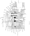
- the safety device 1 shown in FIG. 1 has a housing 4 consisting of an upper part 2 and a lower part 3.
- the lower housing part 3 has two openings arranged next to one another (only one can be seen in FIG. 1), which serve as inlet opening 5 and outlet opening.
- the lower housing part 3 is provided with a flow chamber in the form of a cup-shaped cavity 6, which is closed on the underside and is open on the top.
- the cup-shaped cavity 6 of the lower housing part 3 serves to receive an impeller 7, which is set in rotation by the liquid flowing through the lower housing part 3 of the housing 4.
- the impeller 7 is rotatably supported by means of a bearing pin 8.
- the impeller 7 has a central part 10 Bore 11 extending almost over the entire length of the central part 10.
- a recess 12 is formed in the lower housing part 3, in which the bearing pin 8 is fixed with its underside.
- the impeller 7 with the central part 10 and the central part 10 radially surrounding measuring vanes 9 are carefully centered over the bearing pin 8 in the lower housing part 3 of the housing 4 and then held in a sufficiently centered position so that the upper housing part 2 is easily placed on the lower housing part 3 can.
- the upper housing part 2 has a ring-shaped extension 13, by means of which the upper housing part 2 can be inserted into the cup-shaped cavity 6 of the lower housing part 3.
- lower housing part 3 has a circumferential recess 15 into which an O-ring 16 is inserted for sealing between upper and lower housing parts 2, 3.
- a circular, pot-shaped cavity 17 is formed within the ring-shaped extension 13 of the upper housing part 2 and serves to receive the upper part of the central part 10.
- the cup-shaped cavity 6 and the cup-shaped cavity 17 are designed such that there is sufficient radial play between the impeller 7 and the inner wall of the housing 4.
- the impeller 7 has permanent magnets 19, 20 in its central part 10 at the end facing the upper housing part 2. These are in contactless contact with a stationary Hall cell 21, which is arranged in a recess in the upper housing part 2.
- the impeller forms a first detector element of the safety device. This and the Hall probe a first detector device.
- the projection 13 between the impeller 7 and the inlet 5 or outlet of the safety device 1 is provided with a bore 22 passing through the upper housing part 2.
- An insulation sleeve 23 is arranged within this bore 22, inside which there is in turn a probe screw 24.
- a nut 26 is provided in an upwardly open pot-shaped interior 25 of the upper housing part 2 at the end facing away from the lower housing part 3.
- two contacts 27, 28 are provided, which are insulated from one another by means of an insulation washer 29 surrounding the insulation sleeve 23.
- the top of the pot-shaped interior 25 is closed by a cover 30.
- This cover 30 has for the electrical connection of the detector device 7, 21; 24 with a control device 51, a four-pole plug connection in the form of four tongues 31, 32, 33 (only three of which are shown in FIG. 1) and a bottom 34, formed between the four tongues 31, 32, 33, with a threaded sleeve 35 on.
- the fourth tongue is in front of the sectional plane of the representation of the tongue 31).
- the probe screw 24 is connected to the tongues 31, 33 via wires 36, 37. Not only the mass of the contact 28 via the wire 36, but also the mass of the Hall cell 21 is guided on the tongue 31.
- the threaded sleeve 35 is used to attach a magnetic socket, not shown.
- the upper housing part 2 and the lower housing part 3 have a plurality of through-bores 39, 40, each aligned with one another, for receiving socket head screws 41 on the inlet or outlet side 5. By means of these cheese head screws 41, the upper and lower housing parts 2, 3 are screwed together.
- the impeller 7 is set in rotation by this liquid and this generates a Hall voltage in the Hall cell 21 via the permanent magnets 19, 20 seated in the impeller.
- the detection pulses generated in this way become forwarded to a control device 51, not shown in FIG. 1 (see FIG. 2), and evaluated there. Furthermore, a detection pulse is also sent to the control device via the probe 24 when the liquid flows through the lower housing part 3. If one of these two detection pulses fails, the pump controlled by the control device (see FIG. 2) is switched off.
- detection devices 7, 21; 24 Only when detection pulses from both detection devices 7, 21; 24 the pump is switched on again or only then remains in operation.
- the detection devices are therefore electrically connected by a logical conjunction or AND circuit in the control device.
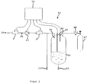
- FIG. 2 shows the arrangement of the device according to the invention with the safety device 1 within a beverage preparation device 42 for producing carbonated water.
- the device according to the invention has a pump 43, in particular a rotary vane pump, on.
- the safety device 1 according to the invention is preferably connected upstream of this rotary vane pump.
- the drinking water flowing in a line 44 is set to a high pressure by the pump 43 and passed on to a nozzle 45.
- the drinking water is then sprayed from this nozzle 45 into a container, in particular a tank 46, which is at least half filled with carbon dioxide gas for the production of carbonated water.
- This carbon dioxide gas comes from a corresponding container 47 and is supplied to the tank 46 via valves 48.
- two probes 49, 50 which are insulated from the tank and are accordingly separated from the electrical ground, are arranged. These probes 49, 50 as well as the pump 43 and the measuring device 1 are each connected to a control device 51.
- the pump 53 is switched on or off via this control device 51.
- outlet tap 52 On the underside of the tank 46 there is an outlet tap 52, via which the carbonated water can be removed from the tank 46.
- a further outlet tap 53 is arranged in front of the nozzle 45, via which non-carbonated water, so-called “still water”, can be removed from the beverage preparation device 42.
- the beverage preparation device 42 for the production of carbonated water has the following function:
- the drinking water originating from an inflow 54 passes through the safety device 1 after the pump 43.
- the drinking water is set to a corresponding predetermined pressure by the pump 43 and conveyed on to a nozzle 45 or to the outlet tap 53.
- the probe and the flow meter are passed on to the control device 51 by the safety device 1. If the pulses from one of these two detection devices are omitted, the control device 51 switches off the pump 43. If it receives pulses from both detection devices again, the pump 53 is accordingly switched on again.
- the water sprayed from the nozzle 45 into the tank 46 dissolves the carbon dioxide fed from the tank 47 to the tank 46 as a water mist.
- the carbonated water "soda water” now collects in the lower half of the tank 46 and can be removed from it via the outlet tap 52.
- the carbonated water produced can now be sold directly or used for the preparation of post-mix drinks, which are beverages made from syrup and carbonated water.
- a measuring device connected downstream of the pump 43 is shown in FIG. 2, which can also perform the function described to increase safety.
- the probes 49, 50 arranged in the tank 46 serve to control the liquid level in the tank 46.
- a corresponding signal is sent to the control device 51, which switches off the pump. Since the entire arrangement is under permanent pressure, the carbonated water is now poured out via the tap 52. If the longer lower probe 49 emerges from the liquid level, a corresponding pulse is again sent to the control device 51, which then switches on the pump 43 again with a delay of 1 to 2 seconds. It becomes carbonated again Water is produced and the liquid level can again rise to the upper probe 50.
- a safety device which provides pump protection in a simple and reliable manner without the need for complex measurements.
Abstract
Description
Die Erfindung betrifft eine Sicherheitseinrichtung zum Einbau in Leitungen für Flüssigkeiten, insbesonders Wasser, einer Getränkebereitungseinrichtung, wobei die Pumpe Flüssigkeit in ein Behältnis fördert, und eine Vorrichtung zum Fördern von Flüssigkeit mit einer Pumpe in einer Flüssigkeitsleitung.The invention relates to a safety device for installation in lines for liquids, in particular water, a beverage preparation device, the pump conveying liquid into a container, and a device for conveying liquid with a pump in a liquid line.
Bei einer aus der Praxis bekannten Getränkebereitungseinrichtung zur Herstellung von kohlensäurehaltigem Wasser "Sodawasser" wird aufbereitetes oder nicht aufbereitetes Leitungswasser, insbesonders aber Trinkwasser, mittels einer Pumpe auf einen hohen Druck eingestellt und über eine Düse in einen zumindest zur Hälfte mit Kohlendioxidgas (Co2) gefüllten Tank versprüht. Das hierdurch entstandene kohlensäurehaltige Wasser sammelt sich in der unteren Hälfte des Tanks. Im Inneren des Tanks befinden sich zwei unterschiedlich lange Sonden, welche mit einer Steuereinrichtung verbunden sind, über die die Pumpe einund ausgeschaltet wird. Sobald das Flüssigkeitsniveau die kürzere, obere Sonde erreicht hat, wird die Pumpe abgeschaltet. Über einen im unteren Bereich des Tanks befindlichen Auslaufhahn kann das kohlensäurehaltige Wasser ausgegeben werden. Tritt dabei die längere Sonde aus dem Flüssigkeitsniveau aus, wird mit einer kleinen Verzögerung etwa 1 bis 2sec. die Pumpe wieder eingeschaltet. Diese fördert erneut Wasser in den Tank und das Flüssigkeitsniveau kann wiederum ansteigen, bis die obere Sonde erreicht ist und die Pumpe wieder ausgeschaltet wird.In a beverage preparation device known from practice for the production of carbonated water “soda water”, treated or non-treated tap water, but especially drinking water, is set to a high pressure by means of a pump and filled with at least half of it with carbon dioxide gas (Co 2 ) Sprayed tank. The resulting carbonated water collects in the lower half of the tank. Inside the tank there are two probes of different lengths, which are connected to a control device that switches the pump on and off. As soon as the liquid level has reached the shorter, upper probe, the pump is switched off. The carbonated water can be dispensed via an outlet tap located in the lower area of the tank. If the longer probe emerges from the liquid level, there is a slight delay of about 1 to 2 seconds. the pump is switched on again. This pumps water back into the tank and the liquid level can rise again until the upper probe is reached and the pump is switched off again.
Den empfindlichsten Teil dieser Getränkebereitungseinrichtung stellt die Pumpe, bei der es sich häufig um eine Drehschieberpumpe handelt, dar. Befindet sich zum Beispiel kein Wasser mehr in der Leitung, dann erfolgt ein Trockenlauf der Pumpe, wodurch ein relativ schneller Defekt dieser Pumpe verusacht wird. Um die Drehschieberpumpe vor einem Defekt zu schützen, wird z.B. vor und nach der Pumpe der Druck gemessen. Erreicht die gemessene Druckdifferenz nicht eine vorgegebene Höhe, dann schaltet die Steuerung die Pumpe aus. Zusätzlich ist teilweise auf der Pumpe ein Wärmesensor angebracht, so daß bei Überschreiten einer vorgegebenen Temperatur ebenfalls ein Ausschalten erfolgt. Nachteilig hierbei ist jedoch, daß in dem Falle, indem aufgrund eines zu hohen Niveaus im Kohlensäure-Tank der Zufluß des Trinkwassers abgestellt wird und damit auf der Ausgangsseite der Pumpe ein zu hoher Druck entsteht, zwar der Differenzdruck zwischen der Eingangs- und der Ausgangsseite die vorgegebene Höhe überschreitet, die Pumpe jedoch das Wasser nur noch über ihr eigenes Druckeinstell- und -überlaufsystem im Kreise fördert. Eine Förderung in den Tank ist dann aber nicht mehr möglich. Außerdem muß bei dieser Einrichtung der Druck jeweils vor und hinter der Pumpe gemessen werden. Dies ist aufwendig, da hierzu zwei Druckmeßeinrichtungen notwendig sind, eine vor und eine hinter der Pumpe. Und zur Wärmemessung ist dann auch noch eine dritte Meßeinrichtung notwendig.The most sensitive part of this beverage preparation device is the pump, which is often a rotary vane pump. For example, if there is no more water in the line, the pump runs dry, causing a relatively quick defect in this pump. In order to protect the rotary vane pump from a defect, the pressure is measured, for example, before and after the pump. If the measured pressure difference does not reach a predetermined level, the control switches the pump off. In addition, a heat sensor is partially installed on the pump, so that it is also switched off when a predetermined temperature is exceeded. The disadvantage here, however, is that in the case where the inflow of drinking water is shut off due to a too high level in the carbon dioxide tank and thus too high a pressure arises on the outlet side of the pump, the differential pressure between the inlet and outlet sides does exceeds the specified height, but the pump only circulates the water via its own pressure setting and overflow system promotes. A pump into the tank is then no longer possible. In addition, the pressure in front of and behind the pump must be measured with this device. This is complex since two pressure measuring devices are necessary for this, one in front and one behind the pump. And a third measuring device is then also necessary for heat measurement.
Aus der EP 251 793 A1 ist eine Flüssigkeits-, insbesondere Bierabgabeeinrichtung bekanntgeworden, die einen elektronischen Steuerkreis mit Reed-Schaltern und Halleffektsensoren aufweist. Der Steuerkreis steuert eine Pumpe zum Fördern der Flüssigkeit von einem Versorgungstank zu Zapfhähnen. Die Reed-Schalter werden durch einen Magneten in einem Schwebekörper betätigt, während der Sensor die Bewegung eines Magneten detektiert, der durch ein druckempfindliches Diaphragma gesteuert wird. Während der Flüssigkeitsabgabe befindet sich der Schwebekörper in seiner (stromab) obersten Stellung und der Sensor reagiert auf den Druck in der Flüssigkeitsleitung. Der Steuerkreis steuert hierdurch automatisch die Pumpe und hält einen Druck in der Leitung auf dem gewünschten Druckniveau aufrecht. Hierdurch wird unabhängig von der Öffnungs- und Schließstellung der Zapfhähne eine nahezu konstante Abgaberate sichergestellt. Mit dem Schutz der Pumpe, insbesondere bei möglichem Trockenlaufen aufgrund leeren Versorgungstankes, befaßt sich diese Druckschrift nicht.From EP 251 793 A1 a liquid, in particular beer, dispenser has become known which has an electronic control circuit with reed switches and Hall effect sensors. The control circuit controls a pump for conveying the liquid from a supply tank to taps. The reed switches are actuated by a magnet in a float, while the sensor detects the movement of a magnet, which is controlled by a pressure-sensitive diaphragm. While the liquid is being dispensed, the float is in its (downstream) uppermost position and the sensor reacts to the pressure in the liquid line. In this way, the control circuit automatically controls the pump and maintains a pressure in the line at the desired pressure level. This ensures an almost constant delivery rate regardless of the opening and closing position of the taps. This document does not deal with the protection of the pump, particularly in the event of possible dry running due to an empty supply tank.
Der Erfindung liegt daher die Aufgabe zugrunde, unter Vermeidung der vorgenannten Nachteile eine Sicherheitseinrichtung der eingangs genannten Art zu schaffen, mit der auf möglichst einfache Weise ein zuverlässiger Schutz der Pumpe erreicht werden kann.The invention is therefore based on the object, while avoiding the aforementioned disadvantages, of creating a safety device of the type mentioned at the outset with which reliable protection of the pump can be achieved in the simplest possible way.
Erfindungsgemäß wird die genannte Aufgabe bei einer Einrichtung der eingangs genannten Art gelöst durch ein Gehäuse mit einer Durchflußkammer mit einem Einlaß und einem Auslaß, durch eine Detektoreinrichtung mit einem in der Durchflußkammer angeordneten Geber in Form eines mit Meßflügeln und einem Zentralteil versehenen Flügelrades und mit einem ersten Detektorelement zur Bestimmung der Durchflußrate der Flüssigkeit, durch eine zweite Detektoreinrichtung in Form einer Sonde zur Detektion des Vorhandenseins von Flüssigkeit und durch eine mit beiden Detektoreinrichtungen verbundene Steuereinrichtung für die Pumpe. Eine erfindungsgemäße Vorrichtung zum Fördern von Flüssigkeit ist dadurch gekennzeichnet, daß in der Flüssigkeitsleitung unmittelbar bei der Pumpe ein Durchflußmeßgerät angeordnet ist, in dessen Innerem ein erster Meßkörper in Form eines mit Meßflügeln und einem Zentralteil versehenen Flügelrades zur Bestimmung des Durchflusses der Flüssigkeit und ein zweiter Meßkörper in Form einer Sonde zur Detektion der Flüssigkeit angeordnet sind, und beide Meßkörper mit einer Steuereinrichtung für die Pumpe verbunden sind, um die Pumpe bei fehlender Flüssigkeit oder zu geringem Flüssigkeitsdurchsatz in der Durchflußkammer stillzusetzen. Aufgrund dieser erfindungsgemäßen Ausgestaltung ist es während des Betriebes zu jeder Zeit möglich, festzustellen, ob eine Förderung des Trinkwassers erfolgt und ob Trinkwasser in der Leitung vorhanden ist. Mit Hilfe dieser Detektionen ist es dann möglich, die Pumpe jederzeit auszuschalten, sobald eine dieser beiden Bedingungen hinsichtlich Förderung und dem Vorhandensein von Wasser in der Leitung nicht mehr gegeben ist. Des weiteren ist nur noch eine einzige Sicherheitseinrichtung zur Durchführung der Feststellungen notwendig.According to the invention, the above object is achieved in a device of the type mentioned in the introduction by a housing with a flow chamber with an inlet and an outlet, by a detector device with a sensor arranged in the flow chamber in the form of an impeller provided with measuring vanes and a central part and with a first one Detector element for determining the flow rate of the liquid, by a second detector device in the form of a probe for detecting the presence of liquid and by a control device for the pump connected to both detector devices. A device for conveying liquid according to the invention is characterized in that a flow meter is arranged in the liquid line directly next to the pump, in the interior of which a first measuring body in the form of an impeller provided with measuring vanes and a central part for determining the flow of the liquid and a second measuring body are arranged in the form of a probe for the detection of the liquid, and both measuring bodies are connected to a control device for the pump in order to stop the pump in the flow chamber if there is no liquid or the liquid flow rate is too low. Due to this embodiment of the invention, it is possible to determine at any time during operation whether the drinking water is being pumped and whether there is drinking water in the line. With the help of these detections, it is then possible to switch off the pump at any time as soon as one of these two conditions with regard to delivery and the presence of water in the line no longer exists. Furthermore, only a single safety device is required to carry out the determinations.
Um die Sicherheitseinrichtung möglichst kompakt auszugestalten, ist in Weiterbildungen vorgesehen, daß das Gehäuse ein Gehäuseunterteil und ein Gehäuseoberteil aufweist und daß das Gehäuseoberteil an dem dem Gehäuseunterteil abgewandten Ende einen topfförmigen Innenraum aufweist, wobei insbesondere das Gehäuse ein Gehäuseoberteil zur Aufnahme der Sonde und ein Gehäuseunterteil zur Aufnahme des Flügelrades aufweist. Die Sonde ist dabei bevorzugt im Gehäuse seitlich des Zentralteils des Flügelrades oberhalb von dessen Meßflügeln angeordnet. Des weiteren ist die Sonde bevorzugt zwischen dem Zentralteil des Flügelrades und dem Einlaß bzw. dem Auslaß des Gehäuses angeordnet. Auf diese Weise wird eine Sicherheitseinrichtung geschaffen, bei der auf optimale Weise bei geringem Raumbedarf eine Unterbringung der für den Pumpenschutz notwendigen Detektionseinrichtungen erfolgt.In order to make the safety device as compact as possible, further developments provide that the housing has a lower housing part and an upper housing part and that the upper housing part has a pot-shaped interior at the end facing away from the lower housing part, in particular the housing an upper housing part for receiving the probe and a lower housing part Includes the impeller. The probe is preferably arranged in the housing on the side of the central part of the impeller above its measuring vanes. Furthermore, the probe is preferably arranged between the central part of the impeller and the inlet or outlet of the housing. In this way, a safety device is created in which the detection devices required for pump protection are accommodated in an optimal manner with a small space requirement.
Bei der Sonde handelt es sich in bevorzugter Ausgestaltung um eine innerhalb einer Isolationshülse angeordnete Sondenschraube. Die Isolationshülse wiederum ist innerhalb einer das Gehäuseoberteil durchsetzenden Bohrung angeordnet. Des weiteren ist in Weiterbildungen vorgesehen, daß die Sondenschraube an dem dem Gehäuseunterteil abgewandten Ende der Bohrung mittels einer Mutter festgelegt ist. Hierzu weist das Gehäuseoberteil bevorzugt auf dem dem Gehäuseunterteil abgewandten Ende einen topfförmigen Innenraum auf. Auf diese Weise sind die Detektionseinrichtungen sowie im weiteren auch Anschlüsse etc. auf engstem Raum platzsparend innerhalb der Sicherheitseinrichtung unterbringbar.In a preferred embodiment, the probe is a probe screw arranged within an insulation sleeve. The insulation sleeve is in turn arranged within a bore penetrating the upper housing part. Furthermore, it is provided in further developments that the probe screw on the lower housing part opposite end of the bore is fixed by a nut. For this purpose, the upper housing part preferably has a pot-shaped interior on the end facing away from the lower housing part. In this way, the detection devices as well as further connections etc. can be accommodated in a space-saving manner within the safety device.
Der topfförmige Innenraum ist an der Oberseite bevorzugt mittels eines Deckels verschlossen. Um eine Verbindung mit der Steuereinrichtung zu schaffen, weist der Deckel einen vierpoligen Steckeranschluß in Form von vier Steckzungen sowie einer an der Unterseite verschlossenen, zwischen den Steckzungen angeordneten Bohrung mit Gewindehülse auf.The pot-shaped interior is preferably closed at the top by means of a lid. In order to create a connection with the control device, the cover has a four-pole plug connection in the form of four tongues and a bore with a threaded sleeve which is closed on the underside and arranged between the tongues.
Um die von der Sonde gemessenen Impulse an die Steuereinrichtung weiterleiten zu können, ist die Sondenschraube mit dem Deckel sowie einer der Steckzungen verbunden.In order to be able to forward the pulses measured by the probe to the control device, the probe screw is connected to the cover and one of the tongues.
Um auf möglichst einfache Weise feststellen zu können, ob eine Förderung und damit ein Durchfluß stattfindet oder nicht, ist in bevorzugter Ausgestaltung vorgesehen, daß das Flügelrad in seinem Zentralteil mit Permanentmagneten versehen ist, welche mit einer in einer Ausnehmung im Boden des topfförmigen Innenraums des Gehäuseoberteils angeordneten stationären Hallzelle in berührungslosem Kontakt stehen. Hierdurch wird mittels des Halleffektes berührungslos und rückwirkungsfrei auf einfache Weise ein Abtastsystem geschaffen, mittels dessen die Pumpe vor einem Trockenlauf wirkungsvoll und einfach geschützt werden kann. Um die mittels des Halleffektes gemessenen Impulse zur Steuereinrichtung weiterleiten zu können, ist die Hallzelle wie die Sonde über den Steckeranschluß mit der Steuereinrichtung verbunden.In order to be able to determine in the simplest possible way whether a conveyance and thus a flow takes place or not, it is provided in a preferred embodiment that the impeller is provided in its central part with permanent magnets, which have a recess in the bottom of the pot-shaped interior of the upper housing part arranged stationary Hall cell are in contactless contact. As a result, a scanning system is created in a simple manner by means of the Hall effect without contact and without feedback, by means of which the pump can be effectively and easily protected against dry running. In order to be able to forward the pulses measured by means of the Hall effect to the control device, the Hall cell and the probe are connected to the control device via the plug connection.
Aufgrund der genannten erfindungsgemäßen Ausgestaltungen ist eine Sicherheitseinrichtung geschaffen, welche durch Integration zweier Meßkörper, nämlich des Flügelrades mit Hallzelle und Permanentmagnet sowie der Sonde, innerhalb eines Gehäuses kompakte und wenig Raum einnehmende Detektionseinrichtungen schafft, durch die einfach und wirkungsvoll ein optimaler Pumpenschutz erreicht werden kann. Es ist lediglich eine Sicherheitseinrichtung notwendig, um die zum Schutz der Pumpe notwendigen Überprüfungen durchzuführen, auch wenn diese zwei Detektionseinrichtungen aufweist, die aber in der Sicherheitseinrichtung integriert ausgebildet sind. Eine Druckmessung vor und hinter der Pumpe sowie eine Temperaturmessung der Pumpentemperatur ist nicht mehr erforderlich. Damit wird die Zahl der notwendigen Sicherheitseinrichtungen auf eine einzige reduziert, welche in bevorzugter Ausgestaltung vor, d.h. im Zulauf zur Pumpe, aber zusätzlich auch hinter der Pumpe zur Durchführung der Messungen angeordnet werden kann. Wenn die Sicherheitseinrichtung im Zulauf der Pumpe angeordnet ist, kann sie schnell festgestellen, ob die Pumpe durch Öffnen eines vorhandenen Überdruckventils im Kreis fördert und sie dann mittels der Steuereinrichtung abstellen.Due to the above-mentioned configurations according to the invention, a safety device is created which, by integrating two measuring bodies, namely the impeller with Hall cell and permanent magnet and the probe, creates compact and little space-consuming detection devices within a housing, by means of which optimal and effective pump protection can be achieved simply and effectively. All that is required is a safety device in order to carry out the checks necessary to protect the pump, even if it has two detection devices, but these are designed to be integrated in the safety device. A pressure measurement in front of and behind the pump and a temperature measurement of the pump temperature is no longer necessary. This reduces the number of necessary safety devices to a single one, which in a preferred embodiment, i.e. can be arranged in the inlet to the pump, but also behind the pump to carry out the measurements. If the safety device is arranged in the inlet of the pump, it can quickly determine whether the pump is circulating by opening an existing pressure relief valve and then switch it off by means of the control device.
Die vom Durchflußdetektor bzw. der Sonde gemessenen Impulse werden jeweils über entsprechende Anschlüsse an die Steuereinrichtung weitergegeben und dort ausgewertet, so daß von dieser direkt bei Fehlen einer der beiden Impulse, entweder denen von der Hallzelle stammenden oder denen von der Sonde stammenden Impulse, sofort ein Abschalten der Pumpe über die Steuereinrichtung erfolgen kann. Die Pumpe wird also sowohl dann abgeschaltet, wenn keine Förderung mehr möglich ist, als auch dann, wenn kein Wasser mehr vorhanden ist, die Pumpe aber Luft fördert.The pulses measured by the flow detector or the probe are each passed on to the control device via corresponding connections and evaluated there, so that in the absence of one of the two pulses, either those originating from the Hall cell or those originating from the probe, immediately one Switch off the pump can take place via the control device. The pump is therefore switched off both when pumping is no longer possible and when there is no more water but the pump is pumping air.
Weitere Vorteile und Merkmale der Erfindung ergeben sich aus den Ansprüchen und aus der nachfolgenden Beschreibung, in der ein Ausführungsbeispiel der Erfindung unter Bezugnahme auf die Zeichnung im einzelnen erläutert ist. Dabei zeigt:
- Figur 1
- die wesentlichen Teile der erfindungsgemäßen Sicherheitseinrichtung im Querschnitt; und
Figur 2- die Einordnung der erfindungsgemäßen Vorrichtung mit Sicherheitseinrichtung innerhalb einer Getränkebereitungseinrichtung.
- Figure 1
- the essential parts of the safety device according to the invention in cross section; and
- Figure 2
- the classification of the device according to the invention with a safety device within a beverage preparation device.
Die in Figur 1 dargestellte Sicherheitseinrichtung 1 weist ein aus einem Oberteil 2 und einem Unterteil 3 bestehendes Gehäuse 4 auf. Das Gehäuseunterteil 3 weist zwei nebeneinander angeordnete Öffnungen (in Figur 1 ist nur eine erkennbar) auf, die als Einlaßöffnung 5 bzw. Auslaßöffnung dienen. Des weiteren ist das Gehäuseunterteil 3 mit einer Durchflußkammer in Form eines topfförmigen Hohlraums 6 versehen, welcher an seiner Unterseite verschlossen und an seiner Oberseite offen ausgebildet ist. Der topfförmige Hohlraum 6 des Gehäuseunterteils 3 dient zur Aufnahme eines Flügelrades 7, welches durch die das Gehäuseunterteil 3 des Gehäuses 4 durchfließende Flüssigkeit in Drehung versetzt wird. Das Flügelrad 7 ist mittels eines Lagerstiftes 8 drehbar gelagert. Hierzu weist das Flügelrad 7 in einem Zentralteil 10 eine sich fast über die gesamte Länge des Zentralteils 10 erstreckende Bohrung 11 auf. Im Gehäuseunterteil 3 ist entsprechend eine Ausnehmung 12 ausgebildet, in welcher der Lagerstift 8 mit seiner Unterseite festgelegt ist. Das Flügelrad 7 mit dem Zentralteil 10 sowie das Zentralteil 10 radial umgebende Meßflügel 9 werden über den Lagerstift 8 sorgfältig zentrierbar im Gehäuseunterteil 3 des Gehäuses 4 eingesetzt und dann in hinreichend zentrierter Stellung gehalten, so daß das Gehäuseoberteil 2 ohne weiteres auf das Gehäuseunterteil 3 aufgesetzt werden kann.The safety device 1 shown in FIG. 1 has a
Das Gehäuseoberteil 2 weist einen sich ringförmig nach unten erstreckenden Ansatz 13 auf, mittels dessen das Gehäuseoberteil 2 in den topfförmigen Hohlraum 6 des Gehäuseunterteils 3 einsetzbar ist. Zur Abdichtung zwischen Gehäuseober- und -unterteil 2,3 weist das Gehäuseunterteil 3 eine umlaufende Aussparung 15 auf, in die zur Abdichtung zwischen Gehäuseober- und -unterteil 2,3 ein O-Ring 16 eingesetzt ist. Innerhalb des ringförmigen Ansatzes 13 des Gehäuseoberteils 2 ist ein kreisrunder, topfförmiger Hohlraum 17 ausgebildet, der zur Aufnahme des oberen Teils des Zentralteils 10 dient.The
Der topfförmige Hohlraum 6 sowie der topfförmige Hohlraum 17 sind derart ausgebildet, daß genügend Radialspiel zwischen dem Flügelrad 7 und der Innenwandung des Gehäuses 4 besteht.The cup-shaped
Das Flügelrad 7 weist in seinem Zentralteil 10 an dem dem Gehäuseoberteil 2 zugewandten Ende Permanentmagnete 19, 20 auf. Diese stehen in berührungslosem Kontakt zu einer stationären Hallzelle 21, welche in einer Ausnehmung des Gehäuseoberteils 2 angeordnet ist. Das Flügelrad bildet ein erstes Detektorelement der Sicherheitseinrichtung. Dieses und die Hallsonde eine erste Detektoreinrichtung.The impeller 7 has
Der Ansatz 13 zwischen dem Flügelrad 7 und dem Einlaß 5 bzw. Auslaß der Sicherheitseinrichtung 1 ist mit einer das Gehäuseoberteil 2 durchsetzenden Bohrung 22 versehen. Innerhalb dieser Bohrung 22 ist eine Isolationshülse 23 angeordnet, in deren Innerem sich wiederum eine Sondenschraube 24 befindet. Zur Befestigung der Sondenschraube 24 ist in einem nach oben offenen topfförmigen Innenraum 25 des Gehäuseoberteils 2 an dem dem Gehäuseunterteil 3 abgewandten Ende eine Mutter 26 vorgesehen. Unterhalb der Mutter 26 sind zwei Kontakte 27, 28 vorgesehen, die mittels einer die Isolationshülse 23 umgebenden Isolationsunterlegscheibe 29 voneinander isoliert sind.The
Der topfförmige Innenraum 25 ist an seiner Oberseite mittels eines Deckels 30 verschlossen. Dieser Deckel 30 weist zur elektrischen Verbindung der Detektoreinrichtung 7, 21; 24 mit einer Steuereinrichtung 51 einen vierpoligen Steckeranschluß in Form von vier Steckzungen 31, 32, 33 (nur drei davon sind in Figur 1 dargestellt) sowie einer an der Unterseite verschlossen, zwischen den vier Steckzungen 31, 32, 33 ausgebildeten Bohrung 34 mit Gewindehülse 35 auf. (Die vierte Steckzunge liegt vor der Schnittebene der Darstellung der Steckzunge 31 gegenüber). Die Sondenschraube 24 ist über Drähte 36, 37 mit den Steckzungen 31,33 verbunden. Auf die Steckzunge 31 ist dabei nicht nur die Masse des Kontaktes 28 über den Draht 36, sondern auch die Masse der Hallzelle 21 geführt. Die Gewindehülse 35 dient zum Befestigen einer nicht dargestellten Magnetsteckdose.The top of the pot-shaped
Das Gehäuseoberteil 2 sowie das Gehäuseunterteil 3 weisen an der Einlaß- bzw. an der Auslaßseite 5 mehrere jeweils zueinander fluchtende Durchbohrungen 39, 40 zur Aufnahme von Zylinderschrauben 41 auf. Mittels dieser Zylinderschrauben 41 werden das Gehäuseober- und das Gehäuseunterteil 2,3 miteinander verschraubt.The
Fließt eine Flüssigkeit, insbesondere Wasser, durch das Gehäuseunterteil 3 des Gehäuses 4, so wird das Flügelrad 7 durch diese Flüssigkeit in Drehung versetzt und diese erzeugt über die im Flügelrad einsitzenden Permanentmagnete 19, 20 eine Hallspannung in der Hallzelle 21. Die derart erzeugten Detektionsimpulse werden an eine in Figur 1 nicht dargestellte Steuereinrichtung 51 (s. Fig. 2) weitergeleitet und dort ausgewertet. Des weiteren wird über die Sonde 24 bei durch das Gehäuseunterteil 3 strömender Flüssigkeit ebenfalls ein Detektionsimpuls an die Steuereinrichtung gesendet. Setzt einer dieser beiden Detektionsimpulse aus, dann wird die über die Steuereinrichtung gesteuerte Pumpe (siehe Figur 2) abgeschaltet.If a liquid, in particular water, flows through the
Erst bei Empfang von Detektionsimpulsen beider Detektionseinrichtungen 7, 21; 24 wird die Pumpe wiederum eingeschaltet bzw. bleibt lediglich dann in Betrieb. Die Detektionseinrichtungen sind also elektrisch durch eine logische Konjunktion bzw. UND-Schaltung in der Steuereinrichtung verbunden.Only when detection pulses from both
In Figur 2 ist die Anordnung der erfindungsgemäßen Vorrichtung mit der Sicherheitseinrichtung 1 innerhalb einer Getränkebereitungseinrichtung 42 zur Erzeugung von kohlesäurehaltigem Wasser dargestellt. Die erfindungsgemäße Vorrichtung weist eine Pumpe 43, insbesondere eine Drehschieberpumpe, auf. Dieser Drehschieberpumpe ist die erfindungsgemäße Sicherheitseinrichtung 1 vorzugsweise vorgeschaltet. Das in einer Leitung 44 strömende Trinkwasser wird von der Pumpe 43 auf einen hohen Druck eingestellt und zu einer Düse 45 weitergeleitet. Von dieser Düse 45 wird das Trinkwasser dann in einen Behälter, insbesondere einen Tank 46 versprüht, welcher zumindest zur Hälfte mit Kohledioxydgas zur Herstellung von kohlesäurehaltigem Wasser gefüllt ist. Dieses Kohlendioxydgas stammt aus einem entsprechenden Behälter 47 und wird über Ventile 48 dem Tank 46 zugeführt. Im Inneren des Tanks 46 sind zwei vom Tank isolierte und entsprechend von der elektrischen Masse getrennte, unterschiedlich lange Sonden 49, 50 angeordnet. Diese Sonden 49, 50 sowie die Pumpe 43 und das Meßgerät 1 sind jeweils mit einer Steuereinrichtung 51 verbunden. Über diese Steuereinrichtung 51 wird die Pumpe 53 jeweils ein- bzw. abgeschaltet.FIG. 2 shows the arrangement of the device according to the invention with the safety device 1 within a
An der Unterseite des Tanks 46 ist ein Auslaufhahn 52 angeordnet, über den das kohlensäurehaltige Wasser dem Tank 46 entnommen werden kann. Ebenso ist vor der Düse 45 ein weiterer Auslaufhahn 53 angeordnet, über den nicht mit "Kohlensäure" versetztes Wasser, sogenanntes "Stilles Wasser" der Getränkebereitungseinrichtung 42 entnommen werden kann.On the underside of the
Die Getränkebereitungseinrichtung 42 zur Herstellung von kohlesäurehaltigem Wasser weist folgende Funktion auf:The
Das von einem Zufluß 54 stammende Trinkwasser durchläuft nach der Pumpe 43 die Sicherheitseinrichtung 1. Das Trinkwasser wird von der Pumpe 43 auf einen entsprechenden vorgegebenen Druck eingestellt und zu einer Düse 45 oder aber zum Auslaufhahn 53 weiterbefördert. Über die Sonde und den Durchflußmesser werden bei vorhandendem Wasserdurchfluß durch die Sicherheitseinrichtung 1 entsprechende Impulse an die Steuereinrichtung 51 weitergeleitet. Entfallen die Impulse einer dieser beiden Detektionseinrichtungen, so schaltet die Steuereinrichtung 51 die Pumpe 43 aus. Werden von diesem wieder Impulse beider Detektionseinrichtungen empfangen, dann wird die Pumpe 53 entsprechend wieder eingeschaltet. Das von der Düse 45 in den Tank 46 versprühte Wasser löst als Wassernebel das vom Behälter 47 dem Tank 46 zugeleitete Kohlendioxyd. In der unteren Hälfte des Tanks 46 sammelt sich nun das kohlensäure- haltige Wasser "Sodawasser", welches diesem über den Auslaufhahn 52 entnommen werden kann. Das hergestellte kohlensäurehaltige Wasser kann nun direkt vertrieben oder aber für die Aufbereitung von Postmixgetränken, dabei handelt es sich um Getränke aus Sirup und kohlensäurehaltigem Wasser, verwendet werden. Zusätzlich ist in der Fig. 2 ein der Pumpe 43 nachgeschaltetes Meßgerät dargestellt, das ebenfalls die beschriebene Funktion zur Erhöhung der Sicherheit ausführen kann.The drinking water originating from an
Die im Tank 46 angeordneten Sonden 49, 50 dienen zur Steuerung des Flüssigkeitsniveaus im Tank 46. Erreicht das Flüssigkeitsniveau die kürzere obere Sonde 50, so wird ein entsprechendes Signal zur Steuereinrichtung 51 gesandt, welche die Pumpe abschaltet. Da die gesamte Anordnung unter permanentem Druck steht, wird nun über den Auslaufhahn 52 das kohlensäurehaltige Wasser ausgeschenkt. Tritt dabei die längere untere Sonde 49 aus dem Flüssigkeitsniveau aus, so wird wiederum ein entsprechender Impuls an die Steuereinrichtung 51 gesandt, welche dann mit einer Verzögerung von 1 bis 2sec die Pumpe 43 wieder einschaltet. Es wird erneut kohlesäurehaltiges Wasser hergestellt, und das Flüssigkeitsniveau kann wiederum bis zur oberen Sonde 50 ansteigen.The
Insgesamt ist damit eine erfindungsgemäße Sicherheitseinrichtung geschaffen, welche auf einfache und zuverlässige Weise einen Pumpenschutz bewirkt, ohne daß aufwendige Messungen hierfür notwendig sind.Overall, a safety device according to the invention is thus created, which provides pump protection in a simple and reliable manner without the need for complex measurements.
Claims (18)
- Safety device for a pump for the installation in conduits for fluids, in particular water, of a beverage preparing equipment, wherein the pump supplies fluid to a receptacle characterized by a housing (4) possessing a through flow chamber with an inlet (5) and an outlet, by a detecting device equipped with a transmitter in a form of an impeller wheel (7) provided with hydrometric vanes (9) and a central piece (10), the transmitter being arranged in the through flow chamber, and with a first detecting element for the detection of the through flow rate of the fluid, by a second detecting device (24) in a form of a probe for detecting the existence of fluid and by a controlling device (51) which is connected to both of the detecting devices to stop the pump (43) when there is no fluid or when the flow rate is too low.
- Safety device according to claim 1, characterized in that probe (24) is located in the inlet area of the through flow chamber (6).
- Safety device according to claims 1 or 2, characterized in that probe (24) is arranged in the housing (4) next to the central piece (10) of the impeller wheel (7) above its hydrometric vanes (9).
- Safety device according to claim 3, characterized in that probe (24) is arranged between the central piece (10) of the impeller wheel (7) and the inlet (5), or the outlet of the housing (4), respectively.
- Safety device according to any of the claims 1 to 4, characterized in that probe (24) is a probe screw (24) located within an insulated covering (23).
- Safety device according to any of the above claims, characterized in that the housing exhibits a lower part of the housing (3) and a upper part of the housing (2) and that the upper part of the housing (2) exhibits a pot-shaped inner space at the averted end of the lower part of the housing (3).
- Safety device according to claim 6, characterized in that the insulated covering (23) is arranged inside a bore going through the upper part of the housing (2).
- Safety device according to one of the claims 3 or 4, characterized in that probe screw (24) is fastened through means of a nut at the end of the bore (22) facing away from the lower part of the housing (3).
- Safety device according to claim 8, characterized in that pot-shaped inner space (25) is closed on the upper side through the means of a lid (30).
- Safety device according to claim 9, characterized in that the lid (30) is provided with a four-pole plug connector in the form of four latches (31, 32, 33) for electrical connection of the measuring bodies (7, 24) with the controlling device (51) as well as with a bore (34) with a threaded sleeve (35), which is closed on the lower part and is arranged between the latches (31, 32, 33).
- Safety device according to claim 10, characterized in that probe screw (24) is connected to the lid (30), likewise to one of the latches (33).
- Safety device according to any of the proceeding claims, characterized in that the impeller wheel (7) is provided in its central piece (10) with permanent magnets (19, 20) being in contract by proximity with a stationary Hall cell (21) located in a recess in the bottom of the pot-shaped inner space (25) of the upper part of the housing (2).
- Safety device according to claim 12, characterized in that the Hall cell (21), like the probe (24), is connected to the controlling device (51) via the connector (31, 32, 33).
- Safety device according to any of the proceeding claims, characterized in that the probe for measuring conductivity is located in the through-flow chamber.
- Safety device according to any of the proceeding claims, characterized in that the housing (4) exhibits a upper part (2) that incorporates the probe (24) and a lower part (3) that incorporates the impeller wheel (7).
- Apparatus for supplying fluid through a pump (43) in a conduit for fluids characterized in that a measuring device is arranged directly at the pump in the conduit for fluids, wherein a first measuring body in the form of an impeller wheel (7) provided with hydrometric vanes (9) and a central piece for the detection of the through flow of the fluid and a second measuring body (24) in a form of a probe for detection of the fluid are arranged in its inner space, and both measuring bodies are connected to a controlling device (51) for the pump (43), to stop the pump when there is no fluid or when the flow rate is too low in the through flow chamber.
- Apparatus according to claim 16, characterized in that the measuring device (1) is located upstream of the pump (43).
- Apparatus according to claim 16, characterized in that the measuring device (1) located downstream of the pump.
Applications Claiming Priority (2)
| Application Number | Priority Date | Filing Date | Title |
|---|---|---|---|
| DE4412045 | 1994-04-08 | ||
| DE4412045A DE4412045A1 (en) | 1994-04-08 | 1994-04-08 | Measuring device for installation in lines for liquids, especially water |
Publications (2)
| Publication Number | Publication Date |
|---|---|
| EP0676367A1 EP0676367A1 (en) | 1995-10-11 |
| EP0676367B1 true EP0676367B1 (en) | 1997-01-22 |
Family
ID=6514861
Family Applications (1)
| Application Number | Title | Priority Date | Filing Date |
|---|---|---|---|
| EP95105063A Expired - Lifetime EP0676367B1 (en) | 1994-04-08 | 1995-04-05 | Safety device for a pump to be installed in pipes for liquids, water in particular, and device for feeding liquid |
Country Status (4)
| Country | Link |
|---|---|
| US (1) | US5651663A (en) |
| EP (1) | EP0676367B1 (en) |
| AT (1) | ATE148075T1 (en) |
| DE (2) | DE4412045A1 (en) |
Families Citing this family (4)
| Publication number | Priority date | Publication date | Assignee | Title |
|---|---|---|---|---|
| US7370776B2 (en) * | 2004-07-16 | 2008-05-13 | St Legend Co., Ltd. | Table for supplying liquid for drinking |
| CA2696117A1 (en) * | 2007-08-15 | 2009-02-19 | Moyno, Inc. | Progressing cavity pump with heat management system |
| US20100180811A1 (en) * | 2009-01-21 | 2010-07-22 | George Sotiriou | Water level detector |
| US8961146B2 (en) | 2010-08-30 | 2015-02-24 | Flow Control LLC | Electronically controlled liquid dispensing system with modular tubing and power design |
Family Cites Families (19)
| Publication number | Priority date | Publication date | Assignee | Title |
|---|---|---|---|---|
| US2462019A (en) * | 1942-01-15 | 1949-02-15 | Wade W Bowman | Beverage dispenser |
| DE1060097B (en) * | 1957-02-11 | 1959-06-25 | Draegerwerk Ag | Secretion pump with upstream collection container for secretion |
| DE1767659C2 (en) * | 1968-05-31 | 1975-10-02 | Chemie Und Filter Gmbh, Verfahrenstechnik Kg, 6900 Heidelberg | Dosing device |
| DE2439789A1 (en) * | 1972-06-23 | 1976-03-04 | Fribue Getraenkemessgeraetever | Metering system for foamed drink taps - has electronic pulse control circuit using piston and cylinder regulated by magnetic element |
| GB1505682A (en) * | 1975-08-05 | 1978-03-30 | Litre Meter Ltd | Metering of fluid flows |
| JPS53123965A (en) * | 1977-04-05 | 1978-10-28 | Aigner Georg | Flow meter for liquids |
| GB1545447A (en) * | 1977-11-05 | 1979-05-10 | Pektron Ltd | Arrangement for dispensing liquids |
| US4345480A (en) * | 1978-02-21 | 1982-08-24 | Basham Edward R | Rotary flow meter |
| JPS5567618A (en) * | 1978-11-17 | 1980-05-21 | Toukiyouto | Liquid meter of electronic integrating type |
| DE2925830A1 (en) * | 1979-06-27 | 1981-01-15 | Rudolf Steffan | Dry-running safety cut=out for pump - uses resistance variation between flow stream and pump housing to disconnect pump motor |
| US4645095A (en) * | 1984-03-19 | 1987-02-24 | Jet Spray Corp. | Syrup sensor for dispensing machine |
| DE8408445U1 (en) * | 1984-03-20 | 1985-01-03 | Plüss, Heinz, Schöndühl | MEASURING DEVICE FOR BEVERAGE LINES |
| DE3608298A1 (en) * | 1986-03-13 | 1986-10-30 | Studzinski, Georg, 4040 Neuss | Flowmeter for liquids, especially beverages |
| GB8616106D0 (en) * | 1986-07-02 | 1986-08-06 | Pektron Ltd | Liquid dispensing arrangement |
| US4848164A (en) * | 1988-05-27 | 1989-07-18 | Graco Inc. | Liquid flow meter |
| JPH0277621A (en) * | 1988-09-14 | 1990-03-16 | Yazaki Corp | Gas meter |
| DE4029616C2 (en) * | 1990-09-19 | 1994-03-03 | Werner Kellermann | Plant for conveying a flow medium |
| IT1246788B (en) * | 1991-04-16 | 1994-11-26 | Ugolini Spa | MACHINE FOR THE DISTRIBUTION OF BEVERAGES |
| DE4142062A1 (en) * | 1991-12-19 | 1993-07-01 | Salzkotten Tankanlagen | Metering system for fuel delivery pump at filling station |
-
1994
- 1994-04-08 DE DE4412045A patent/DE4412045A1/en not_active Withdrawn
-
1995
- 1995-04-05 EP EP95105063A patent/EP0676367B1/en not_active Expired - Lifetime
- 1995-04-05 AT AT95105063T patent/ATE148075T1/en not_active IP Right Cessation
- 1995-04-05 DE DE59500096T patent/DE59500096D1/en not_active Expired - Fee Related
- 1995-04-07 US US08/418,608 patent/US5651663A/en not_active Expired - Fee Related
Also Published As
| Publication number | Publication date |
|---|---|
| DE4412045A1 (en) | 1995-10-12 |
| US5651663A (en) | 1997-07-29 |
| ATE148075T1 (en) | 1997-02-15 |
| EP0676367A1 (en) | 1995-10-11 |
| DE59500096D1 (en) | 1997-03-06 |
Similar Documents
| Publication | Publication Date | Title |
|---|---|---|
| DE2439909A1 (en) | PROCEDURE FOR MIXING AND DISPENSING A BEVERAGE AND BEVERAGE MAKER TO CARRY OUT THIS PROCEDURE | |
| DE19652120A1 (en) | Gasoline vapor recovery device and method | |
| DE69334120T2 (en) | Device for volumetric measurement and regulation of the flow | |
| EP1545805B1 (en) | Rinsing device for a sensor | |
| EP2070865A1 (en) | Rotary distributor with leakage detection | |
| EP0676367B1 (en) | Safety device for a pump to be installed in pipes for liquids, water in particular, and device for feeding liquid | |
| DE60006577T2 (en) | DEVICE FOR DETECTING THE LIQUID HEIGHT IN A COLOR-WATER MIXER | |
| EP3433204A1 (en) | Container-filling assembly | |
| DE3339420C2 (en) | ||
| DE3430907A1 (en) | CIRCUIT ARRANGEMENT FOR REGULATED FILLING AND REFILLING CONTAINERS WITH LIQUIDS | |
| DE202016100854U1 (en) | safety device | |
| EP0236693B1 (en) | Device for observing and controlling a flowable product transported through a tube | |
| DE102006026025A1 (en) | Control element for liquid food has an inlet for a substance, a control area for the substance and an outlet for the substance | |
| EP0240706A1 (en) | Venturi-mixing device for making and dispensing mixed beverages, with rinsing means | |
| EP2988069B1 (en) | Fitting assembly for treating water for heating circuits | |
| EP0914291B1 (en) | Device for the measured transferring of several homogeneous liquids of the same kind | |
| DE3148859C2 (en) | ||
| DE3536992C1 (en) | Device for mixing liquids | |
| EP2669525A1 (en) | Centrifugal pump assembly | |
| DE10361565A1 (en) | Method and device of a beverage line in a dispensing system | |
| DE3608298A1 (en) | Flowmeter for liquids, especially beverages | |
| EP1106228A1 (en) | Device for measuring water flow throughput | |
| DE3210465A1 (en) | Device for detecting the quantity of milk given by a cow during a milking process | |
| DE19959997C2 (en) | water meter | |
| EP0602629A1 (en) | Watertap, in particular water mixer-tap with flow measuring device |
Legal Events
| Date | Code | Title | Description |
|---|---|---|---|
| PUAI | Public reference made under article 153(3) epc to a published international application that has entered the european phase |
Free format text: ORIGINAL CODE: 0009012 |
|
| AK | Designated contracting states |
Kind code of ref document: A1 Designated state(s): AT CH DE ES FR GB IT LI |
|
| 17P | Request for examination filed |
Effective date: 19960301 |
|
| GRAG | Despatch of communication of intention to grant |
Free format text: ORIGINAL CODE: EPIDOS AGRA |
|
| 17Q | First examination report despatched |
Effective date: 19960531 |
|
| GRAH | Despatch of communication of intention to grant a patent |
Free format text: ORIGINAL CODE: EPIDOS IGRA |
|
| GRAH | Despatch of communication of intention to grant a patent |
Free format text: ORIGINAL CODE: EPIDOS IGRA |
|
| GRAA | (expected) grant |
Free format text: ORIGINAL CODE: 0009210 |
|
| AK | Designated contracting states |
Kind code of ref document: B1 Designated state(s): AT CH DE ES FR GB IT LI |
|
| PG25 | Lapsed in a contracting state [announced via postgrant information from national office to epo] |
Ref country code: FR Effective date: 19970122 Ref country code: ES Free format text: THE PATENT HAS BEEN ANNULLED BY A DECISION OF A NATIONAL AUTHORITY Effective date: 19970122 |
|
| REF | Corresponds to: |
Ref document number: 148075 Country of ref document: AT Date of ref document: 19970215 Kind code of ref document: T |
|
| REG | Reference to a national code |
Ref country code: CH Ref legal event code: EP |
|
| REF | Corresponds to: |
Ref document number: 59500096 Country of ref document: DE Date of ref document: 19970306 |
|
| ITF | It: translation for a ep patent filed |
Owner name: 0508;09MIFRACHELI & C. S.R.L. |
|
| GBT | Gb: translation of ep patent filed (gb section 77(6)(a)/1977) |
Effective date: 19970424 |
|
| EN | Fr: translation not filed | ||
| PLBE | No opposition filed within time limit |
Free format text: ORIGINAL CODE: 0009261 |
|
| STAA | Information on the status of an ep patent application or granted ep patent |
Free format text: STATUS: NO OPPOSITION FILED WITHIN TIME LIMIT |
|
| 26N | No opposition filed | ||
| REG | Reference to a national code |
Ref country code: GB Ref legal event code: IF02 |
|
| PGFP | Annual fee paid to national office [announced via postgrant information from national office to epo] |
Ref country code: GB Payment date: 20050404 Year of fee payment: 11 |
|
| PGFP | Annual fee paid to national office [announced via postgrant information from national office to epo] |
Ref country code: AT Payment date: 20050414 Year of fee payment: 11 |
|
| PGFP | Annual fee paid to national office [announced via postgrant information from national office to epo] |
Ref country code: DE Payment date: 20050421 Year of fee payment: 11 |
|
| PG25 | Lapsed in a contracting state [announced via postgrant information from national office to epo] |
Ref country code: GB Free format text: LAPSE BECAUSE OF NON-PAYMENT OF DUE FEES Effective date: 20060405 Ref country code: AT Free format text: LAPSE BECAUSE OF NON-PAYMENT OF DUE FEES Effective date: 20060405 |
|
| PGFP | Annual fee paid to national office [announced via postgrant information from national office to epo] |
Ref country code: IT Payment date: 20060430 Year of fee payment: 12 |
|
| PG25 | Lapsed in a contracting state [announced via postgrant information from national office to epo] |
Ref country code: DE Free format text: LAPSE BECAUSE OF NON-PAYMENT OF DUE FEES Effective date: 20061101 |
|
| GBPC | Gb: european patent ceased through non-payment of renewal fee |
Effective date: 20060405 |
|
| PG25 | Lapsed in a contracting state [announced via postgrant information from national office to epo] |
Ref country code: IT Free format text: LAPSE BECAUSE OF NON-PAYMENT OF DUE FEES Effective date: 20070405 |
|
| PGFP | Annual fee paid to national office [announced via postgrant information from national office to epo] |
Ref country code: CH Payment date: 20090424 Year of fee payment: 15 |
|
| REG | Reference to a national code |
Ref country code: CH Ref legal event code: PL |
|
| PG25 | Lapsed in a contracting state [announced via postgrant information from national office to epo] |
Ref country code: LI Free format text: LAPSE BECAUSE OF NON-PAYMENT OF DUE FEES Effective date: 20100430 Ref country code: CH Free format text: LAPSE BECAUSE OF NON-PAYMENT OF DUE FEES Effective date: 20100430 |