EP0676025B1 - Firebox furnace with automatic feeding system - Google Patents
Firebox furnace with automatic feeding system Download PDFInfo
- Publication number
- EP0676025B1 EP0676025B1 EP94907111A EP94907111A EP0676025B1 EP 0676025 B1 EP0676025 B1 EP 0676025B1 EP 94907111 A EP94907111 A EP 94907111A EP 94907111 A EP94907111 A EP 94907111A EP 0676025 B1 EP0676025 B1 EP 0676025B1
- Authority
- EP
- European Patent Office
- Prior art keywords
- firebox
- grate
- hopper
- funnel
- fuel
- Prior art date
- Legal status (The legal status is an assumption and is not a legal conclusion. Google has not performed a legal analysis and makes no representation as to the accuracy of the status listed.)
- Expired - Lifetime
Links
Images


Classifications
-
- F—MECHANICAL ENGINEERING; LIGHTING; HEATING; WEAPONS; BLASTING
- F23—COMBUSTION APPARATUS; COMBUSTION PROCESSES
- F23B—METHODS OR APPARATUS FOR COMBUSTION USING ONLY SOLID FUEL
- F23B5/00—Combustion apparatus with arrangements for burning uncombusted material from primary combustion
-
- F—MECHANICAL ENGINEERING; LIGHTING; HEATING; WEAPONS; BLASTING
- F23—COMBUSTION APPARATUS; COMBUSTION PROCESSES
- F23B—METHODS OR APPARATUS FOR COMBUSTION USING ONLY SOLID FUEL
- F23B1/00—Combustion apparatus using only lump fuel
- F23B1/16—Combustion apparatus using only lump fuel the combustion apparatus being modified according to the form of grate or other fuel support
-
- F—MECHANICAL ENGINEERING; LIGHTING; HEATING; WEAPONS; BLASTING
- F23—COMBUSTION APPARATUS; COMBUSTION PROCESSES
- F23G—CREMATION FURNACES; CONSUMING WASTE PRODUCTS BY COMBUSTION
- F23G2209/00—Specific waste
- F23G2209/28—Plastics or rubber like materials
- F23G2209/281—Tyres
-
- F—MECHANICAL ENGINEERING; LIGHTING; HEATING; WEAPONS; BLASTING
- F23—COMBUSTION APPARATUS; COMBUSTION PROCESSES
- F23G—CREMATION FURNACES; CONSUMING WASTE PRODUCTS BY COMBUSTION
- F23G2900/00—Special features of, or arrangements for incinerators
- F23G2900/53801—Multi-hearth furnaces with vertical axis
Definitions
- This invention relates to a firebox provided with an automatic fuel feeding system and is an improvement over my previous firebox design as shown in U.S. Design Patent No. DES 270370 of August 30, 1983.
- WO-A-88/02834 discloses a furnace, including a hopper, funnel means, burning grates within a firebox, an ash receiving area, and control means, according to the preamble of claim 1 of the present invention.
- Fireboxes used for heating purposes have enjoyed a new resurgence with the onset of the ecology movement and the desire to avoid the burning of fossil fuels. Additionally, these fireboxes have utility as smelters to liquify metals used in foundry work by blacksmiths, farmers and hobbyists as well as for reclamation and recycling purposes.
- the firebox of this invention is capable of assisting with a solution to the pollution problem by being able to burn aerosol cans, oil filters, tires and other contaminants. After burning the burned containers or steel tire wires can be recycled in a smelting operation. The fact that the container has been scorched, does not act as a detriment in the recycling process.
- the object of the invention is carried out by providing a firebox according to claim 1.
- the firebox includes an automatic material feed hopper for storage of material and subsequent feeding thereof to the enclosure of the firebox.
- An automatic stoking mechanism is also disclosed for movement of the material through the firebox as the combustion process progresses.
- the firebox is provided with a plurality of grates, one located vertically above the other.
- Pivot means may also be provided to cyclically operate the grates to allow for the burning material located thereon to be progressively passed downward through the firebox from an upper to a lower grate during the burning process.
- a simplified ash removal system is disclosed to provide for automatic ash removal.
- an automatic control system for regulating the amount of heat generated and to coordinate the automatic material feeding hopper system with the automatic grates for automatic and controlled stoking of the firebox.
- An exhaust recycling system can be provided to insure complete combustion and an exhaust gas purification system can also be provided.
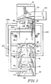
- Figure 1 is a front view of the firebox showing the vertical arrangement of an automatic hopper, an automatic fuel feeder, a funnel door, a manual door, and ash receptor with their power cylinders. Also, the fuel grates are shown in dotted lines.
- Figure 2 is a LEFT side view of the firebox shown in Figure 1 also depicting the power cylinders for an automatic stoker system, and with the automatic control shown schematically.
- Figure 3 is a rear view of the firebox (partially in section) of Figures 1 and 2 and shows an exhaust recycling schematic for the firebox.
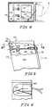
- Figure 4 is a plan view in section of an exhaust gas purifier for a modified firebox with heat exchanger and exhaust gas purifier installed, taken along the line 4-4 of Figure 4.
- Figure 5 is a left side view partially in section of the exhaust gas purifier.
- Figure 6 is a modification of the firebox with the heat exchangers vented externally thereon.
- Figure 7 is a front view of another modification of the firebox with relocated power cylinders, a housing around the actuators and a different hopper arrangement.
- Figure 8 is a side view of the Figure 7 modification.
- Figure 9 is a side view of the Figure 7 modification with the hopper in an open position.
- FIG 1 shows a firebox 10 having a front manually operated door 12.
- the door is mounted to the firebox on generally vertical axial hinges 14 and is held biased to a closed position due to the angling of the front panel 15 of the firebox.
- a pivoting latch lever 16 cooperates with a u-shaped retainer bar 19 to lock the manual door 12 in its closed position.
- the firebox 10 is generally rectangular in shape with side walls 18, 20 and rear wall 22. The firebox is tilted rearwardly as clearly seen in Figure 2.
- the firebox 10 is provided with a handled ash tray 24 at its bottom.
- an auger conveyor (not shown) can be extended through a wall of the firebox 10 to extend into the ash tray to be utilized to withdraw the ashes as the auger rotates and lifts these ashes to a storage receptacle nearby.
- a manual unloading of the tray is possible.
- This tray rests on runners (not shown) and slides outwardly towards the front of the firebox 10 in a drawer-like manner to allow for easy ash removal.
- the tray 24 can have rear or side handles (not shown) to allow for ease in lifting and dumping the ashes from the firebox 10.
- the size of the ash tray 24 is shown schematically and depends on the type of fuel normally intended to be burned and the amount of ash therefrom. The height and volume of the ash tray 24 can thus be varied to suit the type of fuel normally burned. Ideally the ash tray 24 will be sized for the highest ash producing fuels available.
- an exhaust stack and air inlet vents are provided.
- the exhaust stack would be attached to the top 26 of the firebox 10.
- the air-inlets are normal damper openings which are located at the bottom of the firebox 10 at its back 22, front 16, and/or sides 18, 20.
- each of these grates 30, 32, 34 are split in their middle (width-wise as they extend across the firebox) into left 36, 38, 40, and right 42, 44, 46 grate sections (as shown in Figure 1 and right to left as shown in Figure 3).
- Each grate section 36, 38, 40, 42, 44, 46 is fixed to a pivot rod 48 having a crank 50 connected to a piston motor 52.
- Actuation of a respective piston motor causes rotation of its respective crank 50 to rotate each grate section 36, 38, 40, 42, 44, 46 from the shown horizontal position to a vertical position about rod 48 to provide automatic fuel handling "stoking" as the grate sections 36, 38, 40, 42, 44, 46 dumps the fuel thereon to a lower grate 30, 32 or rotate to the ash collector 24 in the case of the lower grate 32.
- the operation of the synchronized control 54 for automatic stoking will be explained later on. While three grates 30, 32, 34 are shown, a more or less number of grates can be utilized.
- a hopper 60 opened at its top (with or without extension 61) is mounted on the front side 15 of the firebox 10 at its upper end by a support frame members 62, 64, 66.
- a fuel feed gate 68 (shown in dotted lines Figures 1 and 2) fixedly attached to shaft 70.
- Motors 72 operate to rotate shaft 70 through cranks 74 to tilt the fuel feed gate 68 clockwise ( Figure 2) to allow metering of fuel, located atop the fuel grate 68, to pass out exit trough portion 76 of the hopper 60.
- a fuel trough entry funnel 78 is located below the hopper 60 and is horizontally pivoted by hinge 80 to the front side 15 of the firebox 10.
- the fuel trough entry funnel 78 has two sides 82 and a front wall 84 with an open top area 86 that underlies the exit portion 76 of the hopper 60.
- the fuel trough entry funnel 78 is pivoted to an open and closed position by motors 88 connected thereto by rods 90.
- the hopper 60 is loaded with fuel through its open top (or top extension 61).
- This entry can be by a batch loader conveyor 140 (see Figure 8) which supplies fuel in measured amounts. This can be accomplished by running the conveyor for a set period of time, or by controlling the conveyor by the weight of fuel on the conveyor or on the fuel grate 60. The fuel rests on fuel grate 68.
- fuel entry funnel 78 is open by motors 88 to have its open top end 86 underlie exit trough portion 76 of hopper 60.
- Motors 72 then pivot fuel grate 68 to allow a metered passage of some or all of the fuel atop the grate to pass by the fuel grate 68 and exit through the exit portion 76 of the hopper 60 into the funnel 78 from whence the fuel is directed onto the top pivoting gate 36 of the firebox where combustion takes place.
- the motors 52 Prior to the feeding of fuel from the trough, the motors 52 are actuated (starting with the bottom motors) to first pivot and empty the lower grate 30 onto the ash drawer 24.
- the intermediate motor 48 is activated to pivot middle grate 32 and empty the middle grate 32 onto the lower grate 30.
- the upper grate 34 is pivoted by the upper motors 48 to empty upper grate 34 onto middle grate 32. In this way, automatic stoking in three stages of burning on the grates 30, 32 and 34 takes place. While three equally spaced (in height) grates 30, 32, 34 have been found to be a most satisfactory number of grates to use, more or less grates can be used and their relative positions with respect to each other and the walls of the firebox can be changed.
- Initial ignition of the firebox 10 can be obtained by opening lower door 12 and starting combustion on middle grate 32 or lower grate 30 or by automatic means.
- control 54 which includes a timer for sequence control. Also provided is a temperature sensor input which can be used to initiate the motor sequencing if the temperature of the area to be heated falls below a set level.
- a clock is provided wherein a user can program set times for the control 54 to begin its sequence. For example, the clock could be set to feed fuel every hour from say 11:00 p.m. to 6:00 a.m. In this manner the firebox would automatically operate throughout the night unattended by a human operator.
- the automatic control has to be set such that the cycle of fuel feeding and automatic stoking is commensurate with the need to insure complete burning of the petroleum based material in the container. No modification of the firebox is necessary since the hopper 60 and grates 30, 32, 34 can already accommodate the contaminate containers.
- FIG 3 shows a firebox wherein an external heat exchanger 100 is provided.
- the firebox 10 can be located outside of the room to be heated and for that a heat exchanger will extend from the firebox 10 into the room to be heated.
- the heat exchanger is shown on the side of the firebox in Figure 3, but it could be located within the firebox ( Figure 6) or on the outside or on the back side.
- a solid flow-check plate 102 Internally of the firebox is a solid flow-check plate 102 to channel the exhaust gases to the heat exchanger 100 which can be of any conventional type, e.g., a fluid radiator, baffle plate design, etc.
- Across the inside of the firebox 10 is a perforated plate 104 to allow the passage of the heated air into the heat exchanger. While Figure 3 shows the heat exchanger 100 located externally of the fire box, the heat exchanger 100 could feed pipes leading to a standard type radiator (not shown) as pictured in Figure 6.
- FIGs 4 and 5 show such a control used on a two door firebox such as shown in my co-pending design application Serial No. 07/724,964 filed July 2, 1991.
- the top door 79 pivots about on vertical axis similarly as door 12.
- the actuating linkage 118 (explained below) would be changed to accommodate the horizontal pivoting door. Suffice it to say that the pollution control device will be located above the uppermost door and below the heat exchanger of Figure 6.
- the pollution control 110 is provided with a door frame plate 112 that has a pivoting door gate 114 pivoted at 116 thereto.
- the door is shown closed in solid lines and open in dotted lines.
- An actuator and linkage 118 is attached to the door gate 114 and to the manually operated door 12. The actuator and linkage 118 pivots the door gate 114 to open a by-pass around the purifier (to be explained later) whenever the manual door 79 is open. This will keep exhaust from pouring out of the opened manual door 79.
- the purification is obtained by reburning of the exhaust gas with a gas fuel from a plurality of gas burners 122.
- the burners 122 are located in a compartment 126 of the firebox 10, and when ignited, shoot a flame out openings 128.
- the gas burners are connected to a source of gas fuel (not shown) in any conventional manner.
- Two or more of a plurality of air passageways 130 are located in the door frame plate 112 and are defined by small cylindrical hollow tubes set in the frame plate 112 to form chimney pipes 124, which can be ceramic or metal and which rest on support strips 128. In this manner the chimney pipe 126 can be replaced by lifting them up, tilting them and dropping them down to the grate 34.
- crescent-shaped air openings 138 are located on the side wall adjacent the gas burners 122.
- the openings 138 have closures 132 which can be pivoted to control the size of the openings. It is has been found that a natural draft will direct the exhaust gas though chimneys where impurities are then burned by the gas burners 122. However, in some installations a draft fan (not shown) may be attached at the inlet used to push the exhaust through the chimneys 126. Additionally having a blower (not shown) to force air through the openings enhances the draft and burning. Again, more than two openings can be utilized to obtain additional air for the combustion process. This is especially true where tires or other contaminated fuels are used.
- a single outlet manifold from a blower can supply air to a plurality of inlets in the side walls of the firebox.
- the inlets would be connected to the manifold like teeth of a fork to the fork handle.
- exhaust recycling can be provided by recirculating exhaust from above the grates 30, 32, and 34 of the firebox to a point at, within or below the grates 30, 32 and 34.
- a manifold 202 is attached to the top portion of the firebox 10 and is connected by conduct 189 (shown schematically in Figure 3) to a lower inlet manifold 184.
- exhaust gas recycling would take place in a two or three grate system (see Figure 3) wherein an abatement plate 200 extends completely across the top of the firebox 10, below the heat exchanger 100, to prevent burnt exhaust gas from flowing up the firebox into the heat exchanger 100. Instead, this burnt smokey exhaust will enter horizontal duct 202 leading to the recirculation duct 180 and be directed back to the firebox below the bottom grate 42.
- FIG. 7-9 firebox is similar to the above except for a different hopper 141 structure (to be explained later) and with a housing cover 142 over the rearwardly located grate 30, 32 and 34, actuators 52 and a side house cover 143 over the entry funnel 78 actuators 88.
- the hopper 141 is in two parts 146, 147 and the front part 147 bottom pivots forwardly about pivot 144 (see difference between Figure 8 and 9) by means of actuator 145 enclosed in a housing 170 which at the same time opens bottom lid 148 in concert with actuator 88 opening funnel 78 to discharge fuel into the funnel.
- a rotable linkage with a pin 150 and slot 151 pivots the bottom 148 in the direction of the arrow ( Figure 9) at the same time as it pivots front hopper part 147.
- the bottom lid 148 has two sides 152, 153 and a back 154 to act as a chute to guide the fuel into the funnel 78, when opened and which sides and back are retracted into the hopper 141 when closed.
- the amount of fuel fed to the hopper can be controlled by the weight of the fuel in the hopper causing the conveyor 140 to stop.
- the hopper 140 is mounted to be vertically adjustable from the dotted line position 157 Figure 8 to the full line as the weight of the fuel increases.
- a bracket 162 is mounted to the firebox 10 by a plurality of struts 163 and has attached thereto a spring 164 connected to a bar 165 attached to the rear portion 147 of the hopper 146 and constrained to move vertically in a slot 166.
- the spring 164 is tensioned and the bar 165 is moved downwardly (direction hollow arrow Figure 9) to allow the hopper to descend.
- the movement of the back of the hopper causes a two part switch 181, 182 to be closed (see Figure 8 and 9) to stop a motor (not shown) that drives the conveyor 140.
Abstract
Description
Claims (13)
- An automatic firebox for heating an area comprising:characterised in that the funnel means comprises a front wall (84) and a top end (86), and is pivotable from a closed position wherein the front wall closes the material entry of the furnace enclosure and the top end (86) of the funnel means (78) is located inside the furnace enclosure to an open position wherein the top end (86) of the funnel means underlies the exit portion of the hopper means (60).a firebox enclosure having at least one material burning grate (30, 32, 34) therein,an upper material hopper means (60) for storage of material,an ash receiving area (24) in or under a lower end of the firebox (10),an upper funnel means (78) for receiving material from the hopper means (60) and passing the material onto the material grate (30, 32, 34) in the firebox enclosure, andcontrol means (54) to control the sequential dumping of material from the material grate (30, 32, 34) into the ash receiving area (24), opening the funnel means (78) to receive material from the hopper means (60), and releasing material from the hopper means,
- The firebox of claim 1, including a door (12) for allowing human access into the firebox (10) and initiation of ignition to start combustion therein.
- The firebox of claim 1 or 2, including at least two material grates (30, 32, 34) in the firebox enclosure, one located vertically above another, wherein the control means (54) first dumps the lower of the grates to the ash receiving area (24) and then dumps the upper of the grates to the lower grate before opening of the funnel means (78).
- The firebox of claim 3, including a third material grate (32) located between the upper and lower material grates (34, 30) wherein the control means (54) dumps the middle grate (32) to the lower grate (30), after the lower grate is dumped to the ash receiving area (24), and then dumps the upper grate (34) to the middle grate (32).
- The firebox of any preceding claim, wherein at least one material grate (30, 32, 34) has two sections (36, 42; 38, 44; 40; 46), each being pivotally mounted within the firebox, and
wherein the control means (54) operates to pivot both grate sections to dump the grate. - The firebox of any preceding claim, wherein the control means (54) is operated in response to the temperature of an area adjacent to the firebox (10) and/or a present clocktime.
- The firebox of any preceding claim, wherein the control means (54) comprises motor means (52) connected to move crank arms (50) that rotate the material grate (30, 32, 34) to dump the grate, rotate the funnel means (78) from its closed to open position, and rotate a material grate (68) of the hopper means (60) to release material to the funnel means.
- The firebox of any preceding claim, wherein external heat exchanger means (100) is attached to the firebox (10), for receiving exhaust gas therefrom to heat an area outside the firebox.
- The firebox of any preceding claim, including exhaust gas purification means to receive and purify exhaust gases just before they exit from a primary combustion area of the firebox (10) comprising:a frame plate (112),chimney means (124) extending through the frame plate to permit passage of gases therethrough, andgas burner means (122) to ignite any impurities in the exhaust gases passing through the chimneys.
- The firebox of claim 9, wherein the chimney means (124) rest in port means in the frame plate (112) on support ledges (128) attached to the frame plate for ease in removal thereof from the firebox (10).
- The firebox of any preceding claim, wherein the control means (54) can be automatically or manually controlled to insure complete combustion of the material utilised in the firebox (10).
- The firebox of any preceding claim, including exhaust gas recirculation means (180, 202) to recirculate burned exhaust gas above the material grate (30, 32, 34) back to a point adjacent the material grate for reburning thereat.
- Use of the firebox of any preceding claim for burning fossil material, preferably aerosol cans, oil filters, and/or automobile tires.
Applications Claiming Priority (3)
| Application Number | Priority Date | Filing Date | Title |
|---|---|---|---|
| US997916 | 1992-12-29 | ||
| US07/997,916 US5261335A (en) | 1992-12-29 | 1992-12-29 | Firebox furnace with automatic feeding system |
| PCT/US1993/012611 WO1994015151A1 (en) | 1992-12-29 | 1993-12-28 | Firebox furnace with automatic feeding system |
Publications (3)
| Publication Number | Publication Date |
|---|---|
| EP0676025A1 EP0676025A1 (en) | 1995-10-11 |
| EP0676025A4 EP0676025A4 (en) | 1998-03-18 |
| EP0676025B1 true EP0676025B1 (en) | 2001-02-14 |
Family
ID=25544556
Family Applications (1)
| Application Number | Title | Priority Date | Filing Date |
|---|---|---|---|
| EP94907111A Expired - Lifetime EP0676025B1 (en) | 1992-12-29 | 1993-12-28 | Firebox furnace with automatic feeding system |
Country Status (5)
| Country | Link |
|---|---|
| US (1) | US5261335A (en) |
| EP (1) | EP0676025B1 (en) |
| JP (1) | JPH08505216A (en) |
| DE (1) | DE69329934T2 (en) |
| WO (1) | WO1994015151A1 (en) |
Families Citing this family (11)
| Publication number | Priority date | Publication date | Assignee | Title |
|---|---|---|---|---|
| GB2286445B (en) * | 1994-02-09 | 1997-12-24 | Lin Wen Chiang Hung | Incinerator |
| US5392719A (en) * | 1994-02-10 | 1995-02-28 | Wen-Chiang; Hung L. | Renovated incinerator |
| WO1998009559A1 (en) * | 1996-09-05 | 1998-03-12 | Ems Technologies Corp. | Organic waste combustor |
| US7665406B2 (en) * | 2003-04-09 | 2010-02-23 | Even Temp, Inc. | Apparatus and method for combustion |
| US7284550B2 (en) * | 2004-03-17 | 2007-10-23 | Bixby Energy Systems, Inc. | Burn pot for furnace |
| US20090266278A1 (en) * | 2008-04-25 | 2009-10-29 | Greenville Manufacturing, Llc | Auto-igniter for biomass furnace |
| CA2730061A1 (en) * | 2008-08-15 | 2010-02-18 | Wayne/Scott Fetzer Company | Biomass fuel furnace system and related methods |
| DE102011109780B3 (en) * | 2011-08-09 | 2013-01-31 | B & 0 Saatinvest Heizhaus OHG | Heating device for dried woodchips for heat supply of e.g. large buildings, has switching device switching empty storage unit from another storage unit, where emptied storage unit is exchanged against full storage unit |
| CN107062910B (en) * | 2016-12-29 | 2022-12-16 | 济南海德热工有限公司 | Automatic feeding equipment for smelting metal magnesium |
| US11125432B2 (en) * | 2018-05-31 | 2021-09-21 | Edward Norbert Endebrock | Solid particle fuel burner |
| US11236905B1 (en) * | 2020-02-18 | 2022-02-01 | Sandra Holman-Thompson | Trash burning receptacle |
Family Cites Families (9)
| Publication number | Priority date | Publication date | Assignee | Title |
|---|---|---|---|---|
| US4331084A (en) * | 1980-05-09 | 1982-05-25 | The Boeing Company | Fuel feed technique for auger combustor |
| USD270370S (en) | 1981-02-25 | 1983-08-30 | Blevins Jr Leslie | Firebox |
| DE3224253A1 (en) * | 1982-06-28 | 1983-12-29 | Buderus Ag, 6330 Wetzlar | Apparatus for feeding heating boilers with solid fuels |
| FR2551843B1 (en) * | 1983-09-14 | 1989-08-18 | Bouron Francis | DEVICE FOR AUTOMATICALLY FEEDING BOILERS WITH SOLID FUEL, ESPECIALLY LOGS |
| US4976209A (en) | 1986-10-11 | 1990-12-11 | Erithglen Limited | Furnaces for incinerating waste material |
| BE1003509A6 (en) * | 1990-01-30 | 1992-04-07 | Keersmaekers Marc | Burning device. |
| US5020453A (en) * | 1990-02-12 | 1991-06-04 | Kabushiki Kaisha Plantec | Vertical incinerator |
| US5022328A (en) * | 1990-08-16 | 1991-06-11 | Ensco, Inc. | Shredder/compactor auger system |
| EP0555501B1 (en) * | 1992-02-12 | 1995-12-13 | Kiyoharu Michimae | Dry distillation type incinerator |
-
1992
- 1992-12-29 US US07/997,916 patent/US5261335A/en not_active Expired - Lifetime
-
1993
- 1993-12-28 WO PCT/US1993/012611 patent/WO1994015151A1/en active IP Right Grant
- 1993-12-28 DE DE69329934T patent/DE69329934T2/en not_active Expired - Fee Related
- 1993-12-28 JP JP6515477A patent/JPH08505216A/en active Pending
- 1993-12-28 EP EP94907111A patent/EP0676025B1/en not_active Expired - Lifetime
Also Published As
| Publication number | Publication date |
|---|---|
| DE69329934T2 (en) | 2003-02-06 |
| WO1994015151A1 (en) | 1994-07-07 |
| EP0676025A1 (en) | 1995-10-11 |
| DE69329934D1 (en) | 2001-03-22 |
| JPH08505216A (en) | 1996-06-04 |
| EP0676025A4 (en) | 1998-03-18 |
| US5261335A (en) | 1993-11-16 |
Similar Documents
| Publication | Publication Date | Title |
|---|---|---|
| EP0235369B1 (en) | Fume burning system | |
| EP0676025B1 (en) | Firebox furnace with automatic feeding system | |
| US7861707B2 (en) | Gravity feed natural draft pellet stove | |
| US3766866A (en) | Thermal waste converter | |
| US4474117A (en) | Boiler using a solid granulated fuel | |
| US4593629A (en) | Solid fuel stoker | |
| CA2447707C (en) | Burner for solid fuel | |
| FI118823B (en) | Combustion process and combustion device | |
| US4347831A (en) | Fuel burning stove | |
| US20080156312A1 (en) | Pellet stove | |
| EP2762777A1 (en) | Boiler | |
| EP0324775B1 (en) | Furnace | |
| WO2010096026A2 (en) | Full automatic smokeless coal burner adjustable for coal type | |
| US1769879A (en) | Incinerator | |
| US3785305A (en) | Incinerator | |
| CA3158827A1 (en) | Bale boiler apparatus and method | |
| US1500348A (en) | Fuel feed for furnaces | |
| US3620177A (en) | Rubbish incinerator | |
| CN113339810A (en) | Be used for domestic waste to burn cleaning equipment | |
| ITVI20080262A1 (en) | HEATING APPLIANCE SUPPLIED WITH SOLID FUEL WITH PERFECT STRUCTURE | |
| GB2196099A (en) | Furnace | |
| RU2125206C1 (en) | Coal incineration for solid domestic wastes | |
| FR2578628A1 (en) | "Burn everything" boiler | |
| US2654330A (en) | Furnace for burning solid fuels such | |
| HU195573B (en) | Boiler particularly for coal firing |
Legal Events
| Date | Code | Title | Description |
|---|---|---|---|
| PUAI | Public reference made under article 153(3) epc to a published international application that has entered the european phase |
Free format text: ORIGINAL CODE: 0009012 |
|
| 17P | Request for examination filed |
Effective date: 19950707 |
|
| AK | Designated contracting states |
Kind code of ref document: A1 Designated state(s): DE |
|
| A4 | Supplementary search report drawn up and despatched |
Effective date: 19980126 |
|
| AK | Designated contracting states |
Kind code of ref document: A4 Designated state(s): DE |
|
| 17Q | First examination report despatched |
Effective date: 19990614 |
|
| GRAG | Despatch of communication of intention to grant |
Free format text: ORIGINAL CODE: EPIDOS AGRA |
|
| GRAG | Despatch of communication of intention to grant |
Free format text: ORIGINAL CODE: EPIDOS AGRA |
|
| GRAG | Despatch of communication of intention to grant |
Free format text: ORIGINAL CODE: EPIDOS AGRA |
|
| GRAH | Despatch of communication of intention to grant a patent |
Free format text: ORIGINAL CODE: EPIDOS IGRA |
|
| GRAH | Despatch of communication of intention to grant a patent |
Free format text: ORIGINAL CODE: EPIDOS IGRA |
|
| GRAA | (expected) grant |
Free format text: ORIGINAL CODE: 0009210 |
|
| AK | Designated contracting states |
Kind code of ref document: B1 Designated state(s): DE |
|
| REF | Corresponds to: |
Ref document number: 69329934 Country of ref document: DE Date of ref document: 20010322 |
|
| EN | Fr: translation not filed | ||
| PLBE | No opposition filed within time limit |
Free format text: ORIGINAL CODE: 0009261 |
|
| STAA | Information on the status of an ep patent application or granted ep patent |
Free format text: STATUS: NO OPPOSITION FILED WITHIN TIME LIMIT |
|
| 26N | No opposition filed | ||
| PGFP | Annual fee paid to national office [announced via postgrant information from national office to epo] |
Ref country code: DE Payment date: 20080131 Year of fee payment: 15 |
|
| PG25 | Lapsed in a contracting state [announced via postgrant information from national office to epo] |
Ref country code: DE Free format text: LAPSE BECAUSE OF NON-PAYMENT OF DUE FEES Effective date: 20090701 |