EP0675324A1 - Lufteinblasssystem für Feuerungsanlage oder Brennkammer und mit einem solchen System ausgerüste Verbrennungsanlage für Biomasse oder Industrieabfälle - Google Patents
Lufteinblasssystem für Feuerungsanlage oder Brennkammer und mit einem solchen System ausgerüste Verbrennungsanlage für Biomasse oder Industrieabfälle Download PDFInfo
- Publication number
- EP0675324A1 EP0675324A1 EP95400597A EP95400597A EP0675324A1 EP 0675324 A1 EP0675324 A1 EP 0675324A1 EP 95400597 A EP95400597 A EP 95400597A EP 95400597 A EP95400597 A EP 95400597A EP 0675324 A1 EP0675324 A1 EP 0675324A1
- Authority
- EP
- European Patent Office
- Prior art keywords
- nozzles
- air
- hearth
- chute
- side wall
- Prior art date
- Legal status (The legal status is an assumption and is not a legal conclusion. Google has not performed a legal analysis and makes no representation as to the accuracy of the status listed.)
- Withdrawn
Links
Images

Classifications
-
- F—MECHANICAL ENGINEERING; LIGHTING; HEATING; WEAPONS; BLASTING
- F23—COMBUSTION APPARATUS; COMBUSTION PROCESSES
- F23M—CASINGS, LININGS, WALLS OR DOORS SPECIALLY ADAPTED FOR COMBUSTION CHAMBERS, e.g. FIREBRIDGES; DEVICES FOR DEFLECTING AIR, FLAMES OR COMBUSTION PRODUCTS IN COMBUSTION CHAMBERS; SAFETY ARRANGEMENTS SPECIALLY ADAPTED FOR COMBUSTION APPARATUS; DETAILS OF COMBUSTION CHAMBERS, NOT OTHERWISE PROVIDED FOR
- F23M5/00—Casings; Linings; Walls
- F23M5/08—Cooling thereof; Tube walls
-
- F—MECHANICAL ENGINEERING; LIGHTING; HEATING; WEAPONS; BLASTING
- F23—COMBUSTION APPARATUS; COMBUSTION PROCESSES
- F23G—CREMATION FURNACES; CONSUMING WASTE PRODUCTS BY COMBUSTION
- F23G5/00—Incineration of waste; Incinerator constructions; Details, accessories or control therefor
- F23G5/002—Incineration of waste; Incinerator constructions; Details, accessories or control therefor characterised by their grates
-
- F—MECHANICAL ENGINEERING; LIGHTING; HEATING; WEAPONS; BLASTING
- F23—COMBUSTION APPARATUS; COMBUSTION PROCESSES
- F23G—CREMATION FURNACES; CONSUMING WASTE PRODUCTS BY COMBUSTION
- F23G5/00—Incineration of waste; Incinerator constructions; Details, accessories or control therefor
- F23G5/08—Incineration of waste; Incinerator constructions; Details, accessories or control therefor having supplementary heating
- F23G5/14—Incineration of waste; Incinerator constructions; Details, accessories or control therefor having supplementary heating including secondary combustion
- F23G5/16—Incineration of waste; Incinerator constructions; Details, accessories or control therefor having supplementary heating including secondary combustion in a separate combustion chamber
-
- F—MECHANICAL ENGINEERING; LIGHTING; HEATING; WEAPONS; BLASTING
- F23—COMBUSTION APPARATUS; COMBUSTION PROCESSES
- F23G—CREMATION FURNACES; CONSUMING WASTE PRODUCTS BY COMBUSTION
- F23G5/00—Incineration of waste; Incinerator constructions; Details, accessories or control therefor
- F23G5/20—Incineration of waste; Incinerator constructions; Details, accessories or control therefor having rotating or oscillating drums
-
- F—MECHANICAL ENGINEERING; LIGHTING; HEATING; WEAPONS; BLASTING
- F23—COMBUSTION APPARATUS; COMBUSTION PROCESSES
- F23G—CREMATION FURNACES; CONSUMING WASTE PRODUCTS BY COMBUSTION
- F23G5/00—Incineration of waste; Incinerator constructions; Details, accessories or control therefor
- F23G5/44—Details; Accessories
- F23G5/442—Waste feed arrangements
- F23G5/444—Waste feed arrangements for solid waste
-
- F—MECHANICAL ENGINEERING; LIGHTING; HEATING; WEAPONS; BLASTING
- F23—COMBUSTION APPARATUS; COMBUSTION PROCESSES
- F23G—CREMATION FURNACES; CONSUMING WASTE PRODUCTS BY COMBUSTION
- F23G7/00—Incinerators or other apparatus for consuming industrial waste, e.g. chemicals
- F23G7/12—Incinerators or other apparatus for consuming industrial waste, e.g. chemicals of plastics, e.g. rubber
-
- F—MECHANICAL ENGINEERING; LIGHTING; HEATING; WEAPONS; BLASTING
- F23—COMBUSTION APPARATUS; COMBUSTION PROCESSES
- F23L—SUPPLYING AIR OR NON-COMBUSTIBLE LIQUIDS OR GASES TO COMBUSTION APPARATUS IN GENERAL ; VALVES OR DAMPERS SPECIALLY ADAPTED FOR CONTROLLING AIR SUPPLY OR DRAUGHT IN COMBUSTION APPARATUS; INDUCING DRAUGHT IN COMBUSTION APPARATUS; TOPS FOR CHIMNEYS OR VENTILATING SHAFTS; TERMINALS FOR FLUES
- F23L9/00—Passages or apertures for delivering secondary air for completing combustion of fuel
- F23L9/02—Passages or apertures for delivering secondary air for completing combustion of fuel by discharging the air above the fire
-
- F—MECHANICAL ENGINEERING; LIGHTING; HEATING; WEAPONS; BLASTING
- F23—COMBUSTION APPARATUS; COMBUSTION PROCESSES
- F23G—CREMATION FURNACES; CONSUMING WASTE PRODUCTS BY COMBUSTION
- F23G2203/00—Furnace arrangements
- F23G2203/10—Stoker grate furnace
-
- F—MECHANICAL ENGINEERING; LIGHTING; HEATING; WEAPONS; BLASTING
- F23—COMBUSTION APPARATUS; COMBUSTION PROCESSES
- F23G—CREMATION FURNACES; CONSUMING WASTE PRODUCTS BY COMBUSTION
- F23G2203/00—Furnace arrangements
- F23G2203/107—Furnace arrangements with vibrating grate
-
- F—MECHANICAL ENGINEERING; LIGHTING; HEATING; WEAPONS; BLASTING
- F23—COMBUSTION APPARATUS; COMBUSTION PROCESSES
- F23G—CREMATION FURNACES; CONSUMING WASTE PRODUCTS BY COMBUSTION
- F23G2205/00—Waste feed arrangements
- F23G2205/18—Waste feed arrangements using airlock systems
-
- F—MECHANICAL ENGINEERING; LIGHTING; HEATING; WEAPONS; BLASTING
- F23—COMBUSTION APPARATUS; COMBUSTION PROCESSES
- F23G—CREMATION FURNACES; CONSUMING WASTE PRODUCTS BY COMBUSTION
- F23G2206/00—Waste heat recuperation
-
- F—MECHANICAL ENGINEERING; LIGHTING; HEATING; WEAPONS; BLASTING
- F23—COMBUSTION APPARATUS; COMBUSTION PROCESSES
- F23G—CREMATION FURNACES; CONSUMING WASTE PRODUCTS BY COMBUSTION
- F23G2209/00—Specific waste
- F23G2209/26—Biowaste
-
- F—MECHANICAL ENGINEERING; LIGHTING; HEATING; WEAPONS; BLASTING
- F23—COMBUSTION APPARATUS; COMBUSTION PROCESSES
- F23G—CREMATION FURNACES; CONSUMING WASTE PRODUCTS BY COMBUSTION
- F23G2209/00—Specific waste
- F23G2209/28—Plastics or rubber like materials
- F23G2209/281—Tyres
-
- F—MECHANICAL ENGINEERING; LIGHTING; HEATING; WEAPONS; BLASTING
- F23—COMBUSTION APPARATUS; COMBUSTION PROCESSES
- F23G—CREMATION FURNACES; CONSUMING WASTE PRODUCTS BY COMBUSTION
- F23G2900/00—Special features of, or arrangements for incinerators
- F23G2900/00001—Exhaust gas recirculation
-
- F—MECHANICAL ENGINEERING; LIGHTING; HEATING; WEAPONS; BLASTING
- F23—COMBUSTION APPARATUS; COMBUSTION PROCESSES
- F23G—CREMATION FURNACES; CONSUMING WASTE PRODUCTS BY COMBUSTION
- F23G2900/00—Special features of, or arrangements for incinerators
- F23G2900/52001—Rotary drums with co-current flows of waste and gas
Definitions
- the present invention relates to an air injection system in a hearth or a combustion chamber and a biomass or industrial waste incineration installation equipped with this system, for example a rotary kiln installation or a grate boiler.
- Such installations or boilers are intended for the combustion or incineration of biomass or industrial waste belonging to two main categories of fuel.
- a first category consists of small aggregates, such as plant residues, bark, hazelnut shells, bagasse, wood shavings, hen litter, stationery sludge, fruit pits, shredded pneumatic tires or the like, allowing a continuous fuel supply to the fireplace.
- the second category consists of larger individual elements, such as whole used pneumatic tires, large agglomerated plates or the like, which are introduced into the hearth by successive charging.
- the present invention therefore aims to eliminate the aforementioned drawbacks and to propose an air injection system in a fireplace which makes it possible to limit the content of unburnt particles in the combustion fumes in a reliable, simple and economical manner, before their treatment with a dust collector.
- the subject of the present invention is an air injection system in a hearth or a combustion chamber comprising a fuel supply chute in the hearth, at least one side wall of which comprises a heat exchanger device bundles of substantially parallel tubes and traversed by a heat transfer agent, such as water, through which device are provided nozzles for spraying air or combustion gases recycled under pressure, characterized in that each pair of nozzles arranged on either side of a tube defines a line which is inclined relative to the vertical.
- the nozzles belonging to the same side wall of the hearth are symmetrical with respect to a vertical median plane perpendicular to said side wall, so as to form a chevron or reverse air flow V in the hearth.
- This arrangement of the nozzles makes it possible to slow the upward flow of the fumes resulting from the combustion of volatile materials and to separate the unburnt particles from the flue gases which fly off.
- certain tubes are bent in the manner of an S to provide a passage between the tubes for the aforementioned nozzles which are housed respectively in each loop of the S.
- the receiving wall of the hearth is cooled jointly by a circulation of water and by a source of air or recycled combustion gases or an air-gas mixture.
- Cooling the grate of the hearth with water or with the combustion gases makes it possible to reduce the supply of oxidizer, and consequently to limit the temperature and the "violence" of the beginning of combustion.
- air projection nozzles or recycled combustion gases are provided in the side wall of the hearth under the lower end of the chute and above the fuel receiving wall.
- Such an air source provided under the fuel introduction chute in the hearth makes it possible to develop a flame in the fire zone located just above the freshly introduced fuel and promotes ignition of the fuel, similar to conventional entry vaults made of refractory material.
- This characteristic therefore makes it possible to eliminate the refractory vault at the level of the entry on the grid, and to achieve savings in maintenance since the refractory materials are generally fragile and require regular maintenance.
- nozzles for projecting air or recycled combustion gases are provided in the side wall of the hearth above the open end of the chute and in a wall opposite the latter.
- the nozzles which are provided above the chute can be supplied by a source of air or recycled combustion gases which sweeps the external face of the upper wall of the chute.
- This so-called secondary air source also makes it possible to stage the combustion in the hearth and to push the main flame towards the center of the hearth.
- these nozzles are all oriented downwards.
- the invention further relates to a biomass or industrial waste incineration plant, equipped with the system defined above.
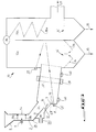
- the installation of the invention is a grate boiler 1 which comprises a fuel supply chute 2 opening at its lower end 3 into a combustion chamber or hearth 4.
- the chute 2 comprises a first upper vertical part 2a which defines a bend 2b with a lower inclined part 2c opening into a side wall 5 of the hearth 4.
- the upper end 6 of the chute 2 has a substantially flared shape to allow fuel to be placed in the oven, for example tires 7.
- a double-valve type airlock is mounted in the vertical part 2a of the chute 2 to ensure both the sequential introduction of the fuel into the hearth 4 and a seal against any combustion risers in the chute 2.
- the airlock is here formed of an upper flap 8a and a lower flap 8b both hinged with respect to a horizontal axis.
- Pressurized air is projected by a nozzle 9 between the upper 8a and lower 8b flaps to form an air barrier in the airlock (the air projection is materialized by an arrow).
- This air barrier establishes an overpressure between the two flaps 8a and 8b of the airlock to prevent the gases produced in the hearth 4 from going up into the chute 2.
- the airlock can consist of two horizontal plates closing the path of the chute 2 and movable in translation under the action for example of a jack.
- An articulated flap forming a deflector 10 is provided on the lower wall 11 of the inclined part 2c of the trough 2.
- the pivoting of the deflector 10 around a horizontal axis 12 can be carried out manually or be controlled by any actuation means such as a hydraulic cylinder.
- the upper and lower faces of the deflector 10 as well as the external face of the lower wall 11 of the chute are swept by air projected by a source of pressurized air 13 to cool the assembly.
- a fan is generally used as a source of pressurized air.
- the lower end 3 of the chute 2 is vertically separated by a drop D of the grid 14 for receiving fuel.
- This drop D must be substantially equal to or greater than the largest dimension of the tire to allow it to fall, for example between 1 and 3 m and preferably greater than 1.5 m.
- the grid 14 is of the type with bars 15 and 15 ′ which can be moved under the action of control jacks generally indicated at 16. A few cylinder rods are shown schematically by dashed lines 17.
- control cylinders 16 and the bars 15 are neither shown nor described in the present application because such an arrangement is generally known in the state of the art.
- the ashes correspond to the residues left by the fuel when it is completely burned.
- it is mainly steel corresponding to the metal reinforcements, zinc oxide and an alumina silicate, used in the composition of tires.
- a source 19 of said primary air projection is associated with the grid 14 by means of a plurality of partitioned compartments 20 which are arranged under the bars 15 and 15 ′ of the grid.
- This projection of primary air participates in the start of combustion as well as in the combustion of solid unburnt products and its flow rate is adjusted by means of the aforementioned compartmentalized compartments 20.
- the primary air may alternatively be replaced by the recycled combustion gases or by an air-gas mixture.
- a cooling water circuit (not shown) is also associated with the grid 14 to ensure its cooling together with the projection of primary air or gas.
- a first part of the grid 14 consists of bars 15 'oriented upwards so that their vertices define a substantially horizontal plane for the reception of the fuel 7' entering the hearth 4.
- a second part of the grid 14 consists of bars 15 superimposed along horizontal planes and which are offset in the direction of movement of the fuel during incineration so that their free ends define a sloping plane opening onto the opening 18 .
- the non-volatile materials in the fuel require a considerable residence time in the hearth to burn completely, which residence time depends on the size of the particles.
- the non-volatile materials consist in particular of carbon black, which represents approximately 23% of the mass of the tire, and burn in 20 minutes, when the temperature is above 1100 ° C, releasing the 25 % of energy remaining.
- This non-volatile material is conveyed to the discharge opening 18 by the movable bars 15 and 15 '.
- the mechanical deflector 10 deflects the trajectory of the tire 7 sliding in the chute 2 and the tire forms a spray 7 'penetrating into the focus 4.
- the angular position of the mechanical deflector 10 makes it possible to determine the point of impact of the burning tire 7 'on the grid 14 so that this burning tire 7' rocks on the grid 14 as close as possible to the side wall 5 of the hearth 4 (see curved arrow).
- volatile matter When the fuel is introduced into the hearth, the volatile matter of the latter quickly escapes on burning and forms a so-called flame front zone.
- volatile matter represents approximately 60% of its mass, which volatile matter, when the temperature is above 1100 ° C, burns during the first minute following the introduction of the tire into the firebox, in particular producing NO x gases and releasing approximately 75% of the total energy supplied by the fuel.
- projection nozzles are provided. so-called lift air 21, front secondary 22a, rear secondary 22b, front tertiary 23a and rear tertiary 23b.
- the lift nozzles 21 are formed in the side wall 5 of the hearth 4 between the lower end 3 of the chute 2 and the grid 14, to help the projection of fuel into the hearth in the case of biomass.
- the projection of air through the nozzles 21 promotes the ignition of the fuel, as indicated by the burning tire 7'represented in broken lines in FIG. 1.
- the nozzles 22a for front secondary air projection and the nozzles 22b for rear rear air projection are formed respectively in the side wall 5 above the chute 2 and in an opposite wall 24 thereof, to assist the combustion of volatile materials released by the fuel.
- the nozzles 23a for the front tertiary air projection and the nozzles 23b for the rear tertiary air projection are provided respectively above the nozzles 22a and 22b and serve to complete the combustion of volatile matter and fine particles in suspension, and to filter the fumes or combustion gases.
- the nozzles 22 and 23 are all oriented downwards so as to cause the return, by pneumatic transport, to the combustion zone of the unburnt particles which take off.
- the nozzles 22a are supplied by a front secondary air source 25 which scans the upper wall 26 of the inclined part 2c of the chute 2 to ensure its cooling.
- nozzles 21, 22 or 23 can project recycled combustion gases in place of air.
- a monitoring window 27 is provided in the side wall 24 of the hearth 4 at the level of the discharge opening 18.
- the side wall 5 of the hearth comprises a heat exchanger device made up of bundles of tubes 28, 28 ′ which are substantially parallel and connected together, for example by welding, in a gas-tight manner by means of '' sheet metal fins 29.
- Certain tubes 28 ′ have a double curvature in the manner of an S to provide a space between the tubes for the air projection nozzles 21 which are housed respectively in each loop of the S.
- the nozzles can be arranged in an inclined direction without deforming the tubes.
- the line 31 passing through two nozzles 21 associated with a tube 28 'in S is inclined at an angle ⁇ between 15 and 45 ° relative to the vertical 30, preferably of the order of 30 °.
- the nozzles 21 belonging to the same side wall 5 of the hearth are symmetrical with respect to a median plane 30 perpendicular to said side wall 5, so as to form an air flow in chevron 31 or in inverted V in the home.
- This chevron flow slows the upward flow of smoke resulting from the combustion of volatile matter, and separates the unburnt particles which fly away.
- the spacing between the nozzles is a function of their diameter so that the upward flow of gases from the grid is allowed but the fine particles in suspension are re-entrained downwards.
- nozzles 21 are arranged in several rows inclined relative to the vertical and parallel to each other, having a multiple curtain effect for capturing unburnt particles.
- FIG. 3 represents an installation 33 with a rotary kiln 32 according to the invention.
- the rotary kiln 32 is slightly inclined relative to the horizontal, for example along a slope of 2%, to ensure the displacement of the unburnt residues from the kiln towards a post-combustion boiler 33a, 33b.
- the boiler shown in FIG. 3 is of the type with two vertical compartments 33a and 33b, or with at least two compartments, which communicate with each other at the upper end of the boiler.
- Schematically shown at 36 are water or steam heat exchanger devices formed for example by bundles of tubes 36a.
- the arrow 37 indicates the direction of flow of the smoke towards a smoke treatment installation such as a dust collector (not shown) or towards a combustion gas recycling installation to supply the aforementioned nozzles.
- the feed chute 2 opens into the oven 32 through a substantially vertical fixed wall 38.
- a lift air projection nozzle 21 ' is formed in the wall 38 under the lower end 3 of the chute 2.
- the nozzle 21' is here oriented upwards, but it can be provided horizontal.
- front air projection nozzles 22a and 23a direct the gases towards the rear air projection nozzles 23b and 22b to re-entrain the end of the downward flow.
- the highest nozzle 23a in the hearth is directed substantially horizontally towards the nozzle 23b which is it oriented downwards.
- the internal wall of the rotary kiln 32 constitutes the wall for receiving the fuel.
Landscapes
- Engineering & Computer Science (AREA)
- Mechanical Engineering (AREA)
- General Engineering & Computer Science (AREA)
- Chemical & Material Sciences (AREA)
- Combustion & Propulsion (AREA)
- Environmental & Geological Engineering (AREA)
- Solid-Fuel Combustion (AREA)
- Gasification And Melting Of Waste (AREA)
Applications Claiming Priority (2)
| Application Number | Priority Date | Filing Date | Title |
|---|---|---|---|
| FR9403611 | 1994-03-28 | ||
| FR9403611A FR2718223B1 (fr) | 1994-03-29 | 1994-03-29 | Dispositif d'enfournement de combustibles solides de grande taille dans un foyer, par exemple des pneus usagés entiers. |
Publications (1)
| Publication Number | Publication Date |
|---|---|
| EP0675324A1 true EP0675324A1 (de) | 1995-10-04 |
Family
ID=9461489
Family Applications (2)
| Application Number | Title | Priority Date | Filing Date |
|---|---|---|---|
| EP95400597A Withdrawn EP0675324A1 (de) | 1994-03-28 | 1995-03-17 | Lufteinblasssystem für Feuerungsanlage oder Brennkammer und mit einem solchen System ausgerüste Verbrennungsanlage für Biomasse oder Industrieabfälle |
| EP95400596A Withdrawn EP0675323A1 (de) | 1994-03-28 | 1995-03-17 | Vorrichtung zur Beschickung einer Verbrennungsanlage mit grossen festen Brennstoffen, zum Beispiel ganze Altreifen |
Family Applications After (1)
| Application Number | Title | Priority Date | Filing Date |
|---|---|---|---|
| EP95400596A Withdrawn EP0675323A1 (de) | 1994-03-28 | 1995-03-17 | Vorrichtung zur Beschickung einer Verbrennungsanlage mit grossen festen Brennstoffen, zum Beispiel ganze Altreifen |
Country Status (3)
| Country | Link |
|---|---|
| EP (2) | EP0675324A1 (de) |
| ES (1) | ES2079342T1 (de) |
| FR (1) | FR2718223B1 (de) |
Cited By (12)
| Publication number | Priority date | Publication date | Assignee | Title |
|---|---|---|---|---|
| EP2016335A2 (de) * | 2006-05-05 | 2009-01-21 | Plasco Energy Group Inc. | Horizontal ausgerichteter vergaser mit seitlichem übertragungssystem |
| EP2029702A1 (de) * | 2006-06-05 | 2009-03-04 | PlascoEnergy IP Holdings, S.L., Bilbao | Vergaser mit vertikal sukzessiven verarbeitungsbereichen |
| US8070863B2 (en) | 2006-05-05 | 2011-12-06 | Plasco Energy Group Inc. | Gas conditioning system |
| WO2011160299A1 (zh) * | 2010-06-23 | 2011-12-29 | Che Zhanbin | 固体燃料燃烧方法、燃烧器及燃烧装置 |
| US8128728B2 (en) | 2006-05-05 | 2012-03-06 | Plasco Energy Group, Inc. | Gas homogenization system |
| US8306665B2 (en) | 2006-05-05 | 2012-11-06 | Plasco Energy Group Inc. | Control system for the conversion of carbonaceous feedstock into gas |
| US8372169B2 (en) | 2006-05-05 | 2013-02-12 | Plasco Energy Group Inc. | Low temperature gasification facility with a horizontally oriented gasifier |
| US8475551B2 (en) | 2006-05-05 | 2013-07-02 | Plasco Energy Group Inc. | Gas reformulating system using plasma torch heat |
| US8690975B2 (en) | 2007-02-27 | 2014-04-08 | Plasco Energy Group Inc. | Gasification system with processed feedstock/char conversion and gas reformulation |
| WO2015051640A1 (en) * | 2013-10-11 | 2015-04-16 | Goldway Technology Limited | Method of providing markings to precious stones including gemstones and diamonds, and markings and marked precious stones marked according to such a method |
| WO2015058409A1 (zh) * | 2013-10-25 | 2015-04-30 | 车战斌 | 固体燃料的燃烧方法和燃烧炉 |
| US9321640B2 (en) | 2010-10-29 | 2016-04-26 | Plasco Energy Group Inc. | Gasification system with processed feedstock/char conversion and gas reformulation |
Families Citing this family (2)
| Publication number | Priority date | Publication date | Assignee | Title |
|---|---|---|---|---|
| CA2374593C (en) * | 1999-05-21 | 2009-02-17 | Barlow Projects, Inc. | Improved mass fuel combustion system |
| DE102017008123A1 (de) * | 2017-08-30 | 2019-02-28 | Martin GmbH für Umwelt- und Energietechnik | Feuerungsanlage und Verfahren zum Betreiben einer Feuerungsanlage |
Citations (3)
| Publication number | Priority date | Publication date | Assignee | Title |
|---|---|---|---|---|
| FR356074A (fr) * | 1905-07-10 | 1905-11-20 | Nicolas Birck | Dispositif d'appareil fumivore pour foyers de tous genres |
| GB1174228A (en) * | 1967-11-28 | 1969-12-17 | Von Roll Ag | Mechanical Equipment for Charging an Incinerating Furnace |
| US5022330A (en) * | 1990-09-12 | 1991-06-11 | Burgher Stephen K | Garbage melter |
Family Cites Families (7)
| Publication number | Priority date | Publication date | Assignee | Title |
|---|---|---|---|---|
| CH443545A (de) * | 1966-01-21 | 1967-09-15 | Von Roll Ag | Beschickungseinrichtung für Verbrennungsöfen für feste, lose und/oder sperrige Abfallstoffe, insbesondere Grob- und Feinmüll |
| US3965828A (en) * | 1975-02-27 | 1976-06-29 | Environmental Control Products, Inc. | Waste feeding apparatus for incinerator |
| US4102278A (en) * | 1977-05-11 | 1978-07-25 | Wyatt Engineers, Inc. | Furnace hogged fuel disperser using modulated airflow |
| DE2853055A1 (de) * | 1978-12-08 | 1980-06-19 | Lentjes Dampfkessel Ferd | Verfahren zur verbrennung von haus- und industriemuell |
| US4905613A (en) * | 1988-09-09 | 1990-03-06 | Detroit Stoker Company | Fuel feeder |
| US5030054A (en) * | 1989-06-23 | 1991-07-09 | Detroit Stoker Company | Combination mechanical/pneumatic coal feeder |
| US5239935A (en) * | 1991-11-19 | 1993-08-31 | Detroit Stoker Company | Oscillating damper and air-swept distributor |
-
1994
- 1994-03-29 FR FR9403611A patent/FR2718223B1/fr not_active Expired - Lifetime
-
1995
- 1995-03-17 EP EP95400597A patent/EP0675324A1/de not_active Withdrawn
- 1995-03-17 EP EP95400596A patent/EP0675323A1/de not_active Withdrawn
- 1995-03-17 ES ES95400596T patent/ES2079342T1/es active Pending
Patent Citations (3)
| Publication number | Priority date | Publication date | Assignee | Title |
|---|---|---|---|---|
| FR356074A (fr) * | 1905-07-10 | 1905-11-20 | Nicolas Birck | Dispositif d'appareil fumivore pour foyers de tous genres |
| GB1174228A (en) * | 1967-11-28 | 1969-12-17 | Von Roll Ag | Mechanical Equipment for Charging an Incinerating Furnace |
| US5022330A (en) * | 1990-09-12 | 1991-06-11 | Burgher Stephen K | Garbage melter |
Cited By (17)
| Publication number | Priority date | Publication date | Assignee | Title |
|---|---|---|---|---|
| US8372169B2 (en) | 2006-05-05 | 2013-02-12 | Plasco Energy Group Inc. | Low temperature gasification facility with a horizontally oriented gasifier |
| US9109172B2 (en) | 2006-05-05 | 2015-08-18 | Plasco Energy Group Inc. | Low temperature gasification facility with a horizontally oriented gasifier |
| EP2016335A2 (de) * | 2006-05-05 | 2009-01-21 | Plasco Energy Group Inc. | Horizontal ausgerichteter vergaser mit seitlichem übertragungssystem |
| US8435315B2 (en) | 2006-05-05 | 2013-05-07 | Plasco Energy Group Inc. | Horizontally-oriented gasifier with lateral transfer system |
| US8128728B2 (en) | 2006-05-05 | 2012-03-06 | Plasco Energy Group, Inc. | Gas homogenization system |
| US8475551B2 (en) | 2006-05-05 | 2013-07-02 | Plasco Energy Group Inc. | Gas reformulating system using plasma torch heat |
| EP2016335A4 (de) * | 2006-05-05 | 2010-06-16 | Plascoenergy Ip Holdings Slb | Horizontal ausgerichteter vergaser mit seitlichem übertragungssystem |
| US8070863B2 (en) | 2006-05-05 | 2011-12-06 | Plasco Energy Group Inc. | Gas conditioning system |
| US8306665B2 (en) | 2006-05-05 | 2012-11-06 | Plasco Energy Group Inc. | Control system for the conversion of carbonaceous feedstock into gas |
| EP2029702A4 (de) * | 2006-06-05 | 2010-08-25 | Plascoenergy Ip Holdings Slb | Vergaser mit vertikal sukzessiven verarbeitungsbereichen |
| EP2029702A1 (de) * | 2006-06-05 | 2009-03-04 | PlascoEnergy IP Holdings, S.L., Bilbao | Vergaser mit vertikal sukzessiven verarbeitungsbereichen |
| US8690975B2 (en) | 2007-02-27 | 2014-04-08 | Plasco Energy Group Inc. | Gasification system with processed feedstock/char conversion and gas reformulation |
| WO2011160299A1 (zh) * | 2010-06-23 | 2011-12-29 | Che Zhanbin | 固体燃料燃烧方法、燃烧器及燃烧装置 |
| US9321640B2 (en) | 2010-10-29 | 2016-04-26 | Plasco Energy Group Inc. | Gasification system with processed feedstock/char conversion and gas reformulation |
| WO2015051640A1 (en) * | 2013-10-11 | 2015-04-16 | Goldway Technology Limited | Method of providing markings to precious stones including gemstones and diamonds, and markings and marked precious stones marked according to such a method |
| US10475355B2 (en) | 2013-10-11 | 2019-11-12 | Chow Tai Fook Jewellery Company Limited | Method of providing markings to precious stones including gemstones and diamonds, and markings and marked precious stones marked according to such a method |
| WO2015058409A1 (zh) * | 2013-10-25 | 2015-04-30 | 车战斌 | 固体燃料的燃烧方法和燃烧炉 |
Also Published As
| Publication number | Publication date |
|---|---|
| FR2718223B1 (fr) | 1996-06-21 |
| FR2718223A1 (fr) | 1995-10-06 |
| ES2079342T1 (es) | 1996-01-16 |
| EP0675323A1 (de) | 1995-10-04 |
Similar Documents
| Publication | Publication Date | Title |
|---|---|---|
| EP0675324A1 (de) | Lufteinblasssystem für Feuerungsanlage oder Brennkammer und mit einem solchen System ausgerüste Verbrennungsanlage für Biomasse oder Industrieabfälle | |
| EP0610114A1 (de) | Verfahren für Feststoffverbrennung, insbesondere für städtische Abfälle, mit umweltfreundlichen festen und gasförmigen Verbrennungsrückständen | |
| US5562053A (en) | Tunnel incinerator | |
| EP0485255B1 (de) | Verfahren und Vorrichtung zur Herstellung von einem festen Brennstoff ausgehend von brennbaren Abfällen | |
| EP0665407A1 (de) | System zum Einspritzen von Schlamm zur Verbrennung in einem Müllverbrennungsofen, Verfahren zu dessen Betrieb und Ofen | |
| EP0173628B1 (de) | Ofen zur Verbrennung von Abfällen | |
| EP0553019B1 (de) | Verfahren zur Verbrennung von festen Brennstoffen mit einem hohen Gehalt an schmelzbaren Aschen und Schwermetallen | |
| FR2761458A1 (fr) | Incinerateur de dechets liquides, pateux et solides | |
| EP2479493B1 (de) | Verbrennungsvorrichtung, Verbrennungseinheit, die eine solche Verbrennungsvorrichtung umfasst, und Verfahren zum Einsatz einer solchen Verbrennungsvorrichtung | |
| GB2303201A (en) | Refuse incinerator | |
| EP3816512A1 (de) | Wärmeerzeugungsmodul, das ein hochtemperatur-filtersystem umfasst | |
| EP3885651B1 (de) | Rotierendes ascherostsystem für brennkammer einer verbrennungs- oder vergasungsanlage | |
| EP0841519A1 (de) | Verfahren und Anlage zur Behandlung durch Verbrennung von Abfällen, und zur Wärmerückgewinnung | |
| BE1028786B1 (fr) | Four pour la production de charbon de bois | |
| FR2458752A1 (fr) | Procede d'incineration de dechets et incinerateur permettant la mise en oeuvre de ce procede | |
| FR2633032A1 (fr) | Auto-incinerateur a combustion etagee et controlee, en particulier pour ordures menageres | |
| EP3472517B1 (de) | Verbrennungsverfahren | |
| FR2930981A1 (fr) | Chaudiere pour combustible solide, liquide ou pulverulent | |
| FR2630812A1 (fr) | Perfectionnement aux chambres de post-combustion | |
| EP0026150A1 (de) | Feste und auch flüssige Brennstoffe verwendendes Heizgerät | |
| WO2022029373A1 (fr) | Four pour chauffe oenologique de bois | |
| EP2573462A1 (de) | Heizanlage für Festbrennstoff vom Typ individualisierte Elemente | |
| FR2961582A1 (fr) | Bruleur anti-machefer | |
| CH270784A (fr) | Foyer mécanique. | |
| EP0047010A2 (de) | Verbrennungseinrichtung, insbesondere für einen Dampfkessel |
Legal Events
| Date | Code | Title | Description |
|---|---|---|---|
| PUAI | Public reference made under article 153(3) epc to a published international application that has entered the european phase |
Free format text: ORIGINAL CODE: 0009012 |
|
| AK | Designated contracting states |
Kind code of ref document: A1 Designated state(s): ES FR GB IT |
|
| 17P | Request for examination filed |
Effective date: 19960401 |
|
| 17Q | First examination report despatched |
Effective date: 19970924 |
|
| STAA | Information on the status of an ep patent application or granted ep patent |
Free format text: STATUS: THE APPLICATION IS DEEMED TO BE WITHDRAWN |
|
| 18D | Application deemed to be withdrawn |
Effective date: 19980205 |