EP0675306B1 - Elektromagnetventil - Google Patents
Elektromagnetventil Download PDFInfo
- Publication number
- EP0675306B1 EP0675306B1 EP95103992A EP95103992A EP0675306B1 EP 0675306 B1 EP0675306 B1 EP 0675306B1 EP 95103992 A EP95103992 A EP 95103992A EP 95103992 A EP95103992 A EP 95103992A EP 0675306 B1 EP0675306 B1 EP 0675306B1
- Authority
- EP
- European Patent Office
- Prior art keywords
- valve
- receptacle
- port
- electrical
- coil
- Prior art date
- Legal status (The legal status is an assumption and is not a legal conclusion. Google has not performed a legal analysis and makes no representation as to the accuracy of the status listed.)
- Expired - Lifetime
Links
Images
Classifications
-
- F—MECHANICAL ENGINEERING; LIGHTING; HEATING; WEAPONS; BLASTING
- F16—ENGINEERING ELEMENTS AND UNITS; GENERAL MEASURES FOR PRODUCING AND MAINTAINING EFFECTIVE FUNCTIONING OF MACHINES OR INSTALLATIONS; THERMAL INSULATION IN GENERAL
- F16K—VALVES; TAPS; COCKS; ACTUATING-FLOATS; DEVICES FOR VENTING OR AERATING
- F16K27/00—Construction of housing; Use of materials therefor
- F16K27/003—Housing formed from a plurality of the same valve elements
-
- B—PERFORMING OPERATIONS; TRANSPORTING
- B60—VEHICLES IN GENERAL
- B60H—ARRANGEMENTS OF HEATING, COOLING, VENTILATING OR OTHER AIR-TREATING DEVICES SPECIALLY ADAPTED FOR PASSENGER OR GOODS SPACES OF VEHICLES
- B60H1/00—Heating, cooling or ventilating devices
- B60H1/00485—Valves for air-conditioning devices, e.g. thermostatic valves
Definitions
- the present invention relates to electrically operated valves and particularly to valves operated by a solenoid for proportional control of flow through the valve in response to an electrical signal. It has been desired to provide such a valve for controlling refrigerant flow in vehicle passenger compartment air conditioning systems such that electronic control of the refrigerant flow to the evaporator may be provided to permit faster response to changing thermal load conditions and improved temperature control of the passenger compartment.
- thermistor temperature sensing elements in sensing ports formed in the valve block in order to provide the necessary temperature inputs to the electrical control system generating the control signal for the valve solenoid.
- the thermistor sensing probes are inserted in sensing ports provided in the side of the valve block; and, the solenoid coil is mounted on the end of the valve block for actuating the valve controlling armature.
- separate electrical connections are required for the coil and for the thermistors in order to connect the valve in circuit with an electronic controller.
- Document US-A-4,835,976 discloses a vapor compression refrigeration system in which a self heated thermistor is located in the suction line downstream of the evaporator to directly sense the quality of the refrigerant flowing thereover.
- the conduit is connected to the inlet of an expansion valve.
- the solenoid of the expension valve has a pair of terminal ends engaging a corresponding pair of pins.
- the attached controller has a four pin connector extending from one side thereof and adapted for connection to a mating four pin plug.
- an electrically operated valve assembly as claimed in claim 1 is provided.
- the present invention provides in a preferred embodiment a solenoid operated valve having sensing ports provided in the valve body or block with thermistors disposed therein and having an encapsulated coil mounted on the body remote from the thermistors.
- An electrical receptacle is mounted on the valve body and has the thermistors connected therethrough to electrical terminals adapted for external connection thereto.
- the solenoid coil has electrical terminals provided on the encapsulation or cover; and, the terminals plug into the electrical receptacle on the valve body as the solenoid operator is attached to the valve body.
- the electrical receptacle mounted to the valve body has electrical terminals disposed for common connection externally both to the thermistors and to the coil such that a single harness connector attached to the receptacle can connect to the coil and the thermistor leads.
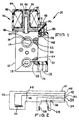
- valve assembly indicated generally at 10 has a body or block 12 with a valve inlet port 14 formed in one side thereof which communicates with a valving chamber 16 which communicates with a valve outlet (not shown).
- An optional through passage 18 may be provided in the valve block which provides a convenient location for sensing temperature but which has no function insofar as the valving operation.
- a valving operator 20 is provided which is operable upon movement to effect flow controlling movement with respect to a valve seat (not shown).
- a sensing port 22 is provided in the valve block and which communicates with inlet 14. If desired an optional second temperature sensing port 24 is provided in the same side of the valve block 12 as port 22. The sensing port 24 communicates with the through passage 18. Passage 22 has a temperature sensing probe such as a thermistor 26 received therein; and, the sensing port 24 similarly has a sensing probe 28 received therein.
- the probes 26,28 are each connected through an electrical receptacle 30 which is attached to the side of the valve block by any convenient expedient, as for example, threaded fasteners (not shown).
- the receptacle 30 has a recess 32 formed in one end thereof, which recess has a plurality of electrical terminal pins extending in a row therein, one of which is shown in FIG. 1 and denoted by reference numeral 34.
- the terminal pin 34 is connected to one lead of the temperature sensing probe 28 and others of the pins in recess 32 are connected to the remaining leads of thermistors 28,26.
- one lead of each of the thermistors 26,28 is connected to junction 36.
- the remaining lead of thermistor 28 is connected to terminal pin 38 in receptacle 30; and, the remaining lead of thermistor 26 is connected to a third pin 40 of receptacle 30.
- the remaining two pins 42,44 in recess 32 of receptacle 30 are connected by leads internal to the receptacle 30 to respectively individual terminals 46,48 provided in a recess 50 formed in the end of receptacle 30 opposite the recess 32.
- an electrical operator subassembly indicated generally at 52 comprises a ferromagnetic armature 54 and nonmagnetic armature guide 56.
- the armature 54 is slidably received in a recess 58 formed in the guide which has an outwardly extending flange portion 60 which is attached to the end of the valve body 12 by any suitable mechanical expedient, as for example, threaded fastening.
- Subassembly 52 includes a plastic coil bobbin 62 received over the armature guide 56 with a plurality of turns of electrical conductor in the form of wire 64 wound about the bobbin to form a coil.
- the coil is preferably encapsulated with plastic material which forms a cover 66 thereover; and, cover 66 also has integrally formed therewith a terminal supporting block or holder portion 68 which extends from one side of the cover 66 and is registered against the end of receptacle 30.
- the holder 68 has inserted therein a pair of electrical connector terminals 70,72 each of which is connected to one end lead of the coil winding 64. Terminals 70,72 are respectively individually in frictional contact with terminals 46,48 upon attachment of the subassembly 52 to the valve body 12. It will be understood that armature 54 is operative upon coil energization to effect movement of valve operator 20 for controlling flow through the valve.
- the present invention thus permits ease of assembly of an electrical valve operator onto the valve body in such a manner as to make bayonet type electrical connection with a receptacle 30 mounted on the side of the valve body.
- the receptacle is also connected to sensing probes in the valve body.
- the solenoid operator 52 and sensing probes 26,28 are connected to electrical terminals extending in a common recess on the end of the receptacle 30 which enables common electrical connection to an external connector through the recess 32.
- the present invention thus provides a simple reliable and cost-effective way of assembling an electrically operated valve, which is particularly suitable for refrigerant expansion valve application and provides for electrical connection to the valve operator and temperature probes mounted on the valve.
Landscapes
- Engineering & Computer Science (AREA)
- General Engineering & Computer Science (AREA)
- Mechanical Engineering (AREA)
- Physics & Mathematics (AREA)
- Thermal Sciences (AREA)
- Magnetically Actuated Valves (AREA)
Claims (5)
- Elektrisch betätigte Ventilanordnung (10), die folgendes aufweist:(a) Körpermittel (12), die einen Einlaßanschluß (14), einen Auslaßanschluß und eine Ventilkammer (16) definieren, und zwar mit einem Ventilglied (20) bewegbar darin zur Steuerung der Strömung zwischen dem Einlaßanschluß (14) und dem Auslaßanschluß;(b) Ankerführungsmittel (56) mit einem sich nach außen erstreckenden Flanschteil (60), der an dem Ende der Körpermittel (12) durch irgendwelche mechanischen Mittel, wie beispielsweise eine Gewindebefestigung, befestigt ist, und darin einen Anker (54) aufweist, der in Folge von Bewegung betätigbar ist, um die Bewegung des erwähnten Ventilglieds (20) zu bewirken.(c) wobei die Körpermittel (12) elektrische Aufnahmemittel (30) mit Mitteln (46, 48) zur elektrischen Steckverbindung aufweisen, und zwar benachbart zu den Ankerführungsmitteln (56);(d) Spulenmittel (62, 64) aufgenommen über den Ankerführungsmitteln (56), wobei die Spulenmittel Anschlußmittel (70, 72) aufweisen, die elektrisch mit der erwähnten Steckverbindung (46, 48) in Eingriff kommen;(e) wobei die Aufnahmemittel (30) andere Anschlußmittel (34) verbunden mit den Aufnahmemitteln aufweisen und geeignet für eine externe elektrische Verbindung damit sind.
- Ventilanordnung (10) nach Anspruch 1, wobei ferner Sensormittel (26, 28) in mindestens einem der Einlaß- und Auslaßanschlüsse vorgesehen sind, wobei die Sensormittel (26, 28) mit den Aufnahmemitteln (30) verbunden sind.
- Ventilanordnung (10) nach Anspruch 1, wobei die Spulenmittel (62) und die Ankerführungsmittel (56) eine Unteranordnung (52) bilden, und zwar befestigt als eine Einheit an den Körpermitteln (12).
- Ventilanordnung (10) nach Anspruch 1, wobei die Körpermittel (12) mindestens einen Abfühlanschluß (22) aufweisen, und wobei die Aufnahmemittel (30) einen Sensor (26) aufweisen, der mit dem erwähnten Anschluß (22) in einer Steckanordnung in Eingriff steht.
- Ventilanordnung (10) nach Anspruch 1, wobei die Körpermittel (12) mindestens einen Abfühlanschluß (22) aufweisen, und wobei die Aufnahmemittel (30) einen Sensor (26) aufweisen, der in den erwähnten Anschluß (22) rechtwinklig zu den Anschlußmitteln/der Steckverbindung (46, 48 und 70, 72) eingesteckt ist.
Applications Claiming Priority (2)
| Application Number | Priority Date | Filing Date | Title |
|---|---|---|---|
| US218783 | 1980-12-22 | ||
| US08/218,783 US5577705A (en) | 1994-03-28 | 1994-03-28 | Coil connection for solenoid operated valve |
Publications (2)
| Publication Number | Publication Date |
|---|---|
| EP0675306A1 EP0675306A1 (de) | 1995-10-04 |
| EP0675306B1 true EP0675306B1 (de) | 2001-10-10 |
Family
ID=22816497
Family Applications (1)
| Application Number | Title | Priority Date | Filing Date |
|---|---|---|---|
| EP95103992A Expired - Lifetime EP0675306B1 (de) | 1994-03-28 | 1995-03-17 | Elektromagnetventil |
Country Status (4)
| Country | Link |
|---|---|
| US (1) | US5577705A (de) |
| EP (1) | EP0675306B1 (de) |
| DE (1) | DE69523085T2 (de) |
| ES (1) | ES2163456T3 (de) |
Families Citing this family (2)
| Publication number | Priority date | Publication date | Assignee | Title |
|---|---|---|---|---|
| US5704585A (en) * | 1995-08-29 | 1998-01-06 | Siemens Electric Limited | Electrical connection between closure cap and internal actuator of an electrically actuated valve |
| US6076803A (en) * | 1999-03-12 | 2000-06-20 | Snap-Tite Technologies, Inc. | Axial flow solenoid valve |
Family Cites Families (9)
| Publication number | Priority date | Publication date | Assignee | Title |
|---|---|---|---|---|
| US3580267A (en) * | 1969-09-26 | 1971-05-25 | Ralph J Baker | Condensate valve |
| JPS589307B2 (ja) * | 1978-08-23 | 1983-02-19 | 株式会社日立製作所 | 比例形電磁弁 |
| NZ223460A (en) * | 1988-02-09 | 1993-01-27 | Fisher & Paykel | Flow control system for two liquids entering a mixing chamber to maintain a desired temperature |
| US4835976A (en) * | 1988-03-14 | 1989-06-06 | Eaton Corporation | Controlling superheat in a refrigeration system |
| US4892285A (en) * | 1988-04-29 | 1990-01-09 | Eaton Corporation | Modulated electrically operated refrigerant expansion valve |
| DE3819761A1 (de) * | 1988-06-10 | 1989-12-14 | Vib Apparatebau Gmbh | Digitalventilsystem |
| GB9002839D0 (en) * | 1990-02-08 | 1990-04-04 | Lucas Ind Plc | Fuel injection nozzle |
| US4984735A (en) * | 1990-03-19 | 1991-01-15 | Eaton Corporation | Sensing refrigerant temperature in a thermostatic expansion valve |
| DE4105705A1 (de) * | 1991-02-21 | 1992-09-03 | Mannesmann Ag | Ventileinrichtung |
-
1994
- 1994-03-28 US US08/218,783 patent/US5577705A/en not_active Expired - Fee Related
-
1995
- 1995-03-17 EP EP95103992A patent/EP0675306B1/de not_active Expired - Lifetime
- 1995-03-17 ES ES95103992T patent/ES2163456T3/es not_active Expired - Lifetime
- 1995-03-17 DE DE69523085T patent/DE69523085T2/de not_active Expired - Fee Related
Also Published As
| Publication number | Publication date |
|---|---|
| US5577705A (en) | 1996-11-26 |
| EP0675306A1 (de) | 1995-10-04 |
| ES2163456T3 (es) | 2002-02-01 |
| DE69523085T2 (de) | 2002-07-11 |
| DE69523085D1 (de) | 2001-11-15 |
Similar Documents
| Publication | Publication Date | Title |
|---|---|---|
| US4720078A (en) | Solenoid valve | |
| US6336361B1 (en) | Flow rate sensor with symmetrical support protective member and structural member | |
| US6056908A (en) | Integrated transmission control system | |
| US4756166A (en) | Integral receiver/dehydrator and expansion valve for air conditioning systems | |
| US4362027A (en) | Refrigeration control system for modulating electrically-operated expansion valves | |
| US7383851B2 (en) | Closed loop pressure control system and electrically operated pressure control valve with integral pressure sensor and method of making same | |
| KR101092676B1 (ko) | 일체된 압력 센서를 갖는 전자기식 압력 조절 밸브 장치 | |
| CN110753824A (zh) | 用于确定电磁阀柱塞位置的集成系统及其方法 | |
| JP2004068814A (ja) | 電気作動弁組立体およびその製造方法 | |
| EP0907057A1 (de) | Thermostatisches Expansionsventil mit integriertem, elektrisch betätigbarem Einlassventil | |
| JP2019504248A (ja) | 電気接続装置 | |
| EP0675306B1 (de) | Elektromagnetventil | |
| JPH1137876A (ja) | 圧力検出装置 | |
| US5605318A (en) | Electric expansion valve | |
| CA1291802C (en) | Thermal sensor assembly | |
| US4866410A (en) | Thermal sensor assembly | |
| CN1208140A (zh) | 电致动的气动阀装置 | |
| EP0539944A2 (de) | Expansionsventil und temperaturfühlende Anordnung dafür | |
| US2844321A (en) | Proportionate flow control device | |
| US20030102955A1 (en) | Combined pressure responsive electrical switch and temperature sensor device | |
| JP2006274872A (ja) | 車両用の機能性部品 | |
| US4139151A (en) | Electric thermal switch valve | |
| US4703739A (en) | Engine auxiliary starting device | |
| JPS63268944A (ja) | 内燃機関の温度検知装置 | |
| JP4026301B2 (ja) | 蒸気圧縮式冷凍サイクル用の減圧器 |
Legal Events
| Date | Code | Title | Description |
|---|---|---|---|
| PUAI | Public reference made under article 153(3) epc to a published international application that has entered the european phase |
Free format text: ORIGINAL CODE: 0009012 |
|
| AK | Designated contracting states |
Kind code of ref document: A1 Designated state(s): DE ES FR GB IT |
|
| 17P | Request for examination filed |
Effective date: 19960403 |
|
| 17Q | First examination report despatched |
Effective date: 19970616 |
|
| RTI1 | Title (correction) |
Free format text: SOLENOID OPERATED VALVE |
|
| RTI1 | Title (correction) |
Free format text: SOLENOID OPERATED VALVE |
|
| GRAG | Despatch of communication of intention to grant |
Free format text: ORIGINAL CODE: EPIDOS AGRA |
|
| GRAG | Despatch of communication of intention to grant |
Free format text: ORIGINAL CODE: EPIDOS AGRA |
|
| GRAH | Despatch of communication of intention to grant a patent |
Free format text: ORIGINAL CODE: EPIDOS IGRA |
|
| GRAH | Despatch of communication of intention to grant a patent |
Free format text: ORIGINAL CODE: EPIDOS IGRA |
|
| GRAA | (expected) grant |
Free format text: ORIGINAL CODE: 0009210 |
|
| AK | Designated contracting states |
Kind code of ref document: B1 Designated state(s): DE ES FR GB IT |
|
| REF | Corresponds to: |
Ref document number: 69523085 Country of ref document: DE Date of ref document: 20011115 |
|
| REG | Reference to a national code |
Ref country code: GB Ref legal event code: IF02 |
|
| REG | Reference to a national code |
Ref country code: ES Ref legal event code: FG2A Ref document number: 2163456 Country of ref document: ES Kind code of ref document: T3 |
|
| ET | Fr: translation filed | ||
| PLBE | No opposition filed within time limit |
Free format text: ORIGINAL CODE: 0009261 |
|
| STAA | Information on the status of an ep patent application or granted ep patent |
Free format text: STATUS: NO OPPOSITION FILED WITHIN TIME LIMIT |
|
| 26N | No opposition filed | ||
| PGFP | Annual fee paid to national office [announced via postgrant information from national office to epo] |
Ref country code: GB Payment date: 20030204 Year of fee payment: 9 |
|
| PGFP | Annual fee paid to national office [announced via postgrant information from national office to epo] |
Ref country code: FR Payment date: 20030303 Year of fee payment: 9 |
|
| PGFP | Annual fee paid to national office [announced via postgrant information from national office to epo] |
Ref country code: ES Payment date: 20030320 Year of fee payment: 9 |
|
| PGFP | Annual fee paid to national office [announced via postgrant information from national office to epo] |
Ref country code: DE Payment date: 20030331 Year of fee payment: 9 |
|
| PG25 | Lapsed in a contracting state [announced via postgrant information from national office to epo] |
Ref country code: GB Free format text: LAPSE BECAUSE OF NON-PAYMENT OF DUE FEES Effective date: 20040317 |
|
| PG25 | Lapsed in a contracting state [announced via postgrant information from national office to epo] |
Ref country code: ES Free format text: LAPSE BECAUSE OF NON-PAYMENT OF DUE FEES Effective date: 20040318 |
|
| PG25 | Lapsed in a contracting state [announced via postgrant information from national office to epo] |
Ref country code: DE Free format text: LAPSE BECAUSE OF NON-PAYMENT OF DUE FEES Effective date: 20041001 |
|
| GBPC | Gb: european patent ceased through non-payment of renewal fee |
Effective date: 20040317 |
|
| PG25 | Lapsed in a contracting state [announced via postgrant information from national office to epo] |
Ref country code: FR Free format text: LAPSE BECAUSE OF NON-PAYMENT OF DUE FEES Effective date: 20041130 |
|
| REG | Reference to a national code |
Ref country code: FR Ref legal event code: ST |
|
| PG25 | Lapsed in a contracting state [announced via postgrant information from national office to epo] |
Ref country code: IT Free format text: LAPSE BECAUSE OF NON-PAYMENT OF DUE FEES Effective date: 20050317 |
|
| REG | Reference to a national code |
Ref country code: ES Ref legal event code: FD2A Effective date: 20040318 |