EP0673593A1 - Method and apparatus for conveying crop or the like - Google Patents
Method and apparatus for conveying crop or the like Download PDFInfo
- Publication number
- EP0673593A1 EP0673593A1 EP19940301886 EP94301886A EP0673593A1 EP 0673593 A1 EP0673593 A1 EP 0673593A1 EP 19940301886 EP19940301886 EP 19940301886 EP 94301886 A EP94301886 A EP 94301886A EP 0673593 A1 EP0673593 A1 EP 0673593A1
- Authority
- EP
- European Patent Office
- Prior art keywords
- projections
- roller conveyor
- spiral
- conveyor element
- rotation
- Prior art date
- Legal status (The legal status is an assumption and is not a legal conclusion. Google has not performed a legal analysis and makes no representation as to the accuracy of the status listed.)
- Granted
Links
- 238000000034 method Methods 0.000 title claims abstract description 5
- 239000000463 material Substances 0.000 claims abstract description 11
- 238000004140 cleaning Methods 0.000 claims description 19
- 235000002595 Solanum tuberosum Nutrition 0.000 description 3
- 244000061456 Solanum tuberosum Species 0.000 description 3
- 230000000694 effects Effects 0.000 description 2
- 230000004048 modification Effects 0.000 description 2
- 238000012986 modification Methods 0.000 description 2
- 230000000750 progressive effect Effects 0.000 description 2
- 239000012858 resilient material Substances 0.000 description 2
- 239000002689 soil Substances 0.000 description 2
- 230000004323 axial length Effects 0.000 description 1
- 238000010276 construction Methods 0.000 description 1
- 229920003052 natural elastomer Polymers 0.000 description 1
- 229920001194 natural rubber Polymers 0.000 description 1
- 229920000642 polymer Polymers 0.000 description 1
- 229920003051 synthetic elastomer Polymers 0.000 description 1
- 239000005061 synthetic rubber Substances 0.000 description 1
- 239000002699 waste material Substances 0.000 description 1
Images


Classifications
-
- B—PERFORMING OPERATIONS; TRANSPORTING
- B07—SEPARATING SOLIDS FROM SOLIDS; SORTING
- B07B—SEPARATING SOLIDS FROM SOLIDS BY SIEVING, SCREENING, SIFTING OR BY USING GAS CURRENTS; SEPARATING BY OTHER DRY METHODS APPLICABLE TO BULK MATERIAL, e.g. LOOSE ARTICLES FIT TO BE HANDLED LIKE BULK MATERIAL
- B07B1/00—Sieving, screening, sifting, or sorting solid materials using networks, gratings, grids, or the like
- B07B1/46—Constructional details of screens in general; Cleaning or heating of screens
- B07B1/4609—Constructional details of screens in general; Cleaning or heating of screens constructional details of screening surfaces or meshes
- B07B1/4636—Regulation of screen apertures
-
- A—HUMAN NECESSITIES
- A01—AGRICULTURE; FORESTRY; ANIMAL HUSBANDRY; HUNTING; TRAPPING; FISHING
- A01D—HARVESTING; MOWING
- A01D17/00—Digging machines with sieving and conveying mechanisms
- A01D17/06—Digging machines with sieving and conveying mechanisms with rollers or disc screens
-
- A—HUMAN NECESSITIES
- A01—AGRICULTURE; FORESTRY; ANIMAL HUSBANDRY; HUNTING; TRAPPING; FISHING
- A01D—HARVESTING; MOWING
- A01D33/00—Accessories for digging harvesters
- A01D33/08—Special sorting and cleaning mechanisms
-
- B—PERFORMING OPERATIONS; TRANSPORTING
- B07—SEPARATING SOLIDS FROM SOLIDS; SORTING
- B07B—SEPARATING SOLIDS FROM SOLIDS BY SIEVING, SCREENING, SIFTING OR BY USING GAS CURRENTS; SEPARATING BY OTHER DRY METHODS APPLICABLE TO BULK MATERIAL, e.g. LOOSE ARTICLES FIT TO BE HANDLED LIKE BULK MATERIAL
- B07B1/00—Sieving, screening, sifting, or sorting solid materials using networks, gratings, grids, or the like
- B07B1/12—Apparatus having only parallel elements
- B07B1/14—Roller screens
- B07B1/15—Roller screens using corrugated, grooved or ribbed rollers
- B07B1/155—Roller screens using corrugated, grooved or ribbed rollers the rollers having a star shaped cross section
-
- B—PERFORMING OPERATIONS; TRANSPORTING
- B65—CONVEYING; PACKING; STORING; HANDLING THIN OR FILAMENTARY MATERIAL
- B65G—TRANSPORT OR STORAGE DEVICES, e.g. CONVEYORS FOR LOADING OR TIPPING, SHOP CONVEYOR SYSTEMS OR PNEUMATIC TUBE CONVEYORS
- B65G45/00—Lubricating, cleaning, or clearing devices
- B65G45/005—Cleaning conveyor screws
Definitions
- This invention relates to a method and apparatus for conveying or cleaning crop or the like.
- An example of the use of the invention is the cleaning of a harvested potato crop.
- the invention may find application to many other such crops and may be used in crop and the like conveyors in any situation where it is desired to remove soil or crop material or other material from conveyor elements.
- One application of the invention would be for use in a potato or like crop harvester.
- crop or the like conveying apparatus in which driveable spiral roller conveyor elements are each provided with a plurality of projections mounted adjacent these conveyor elements at intervals along the length thereof so as to mesh with the spirals to remove material therefrom. In this way a convenient cleaning action is performed on the roller conveyor elements.
- the projections are mounted on a shaft, arranged to be rotated and driven in the opposite direction to the roller conveyor elements and are constructed of a resilient material.
- the projections are provided with a simple means for giving them the necessary positive cleaning action. This is accentuated by the opposite direction of rotation of the projections.
- provision of these in resilient form enables them to snap or click-over successive portions of the spiral rotating conveyor elements as cleaning progresses. This action has an inherent cleaning effect on the co-operating parts and contributes to the overall cleaning effect.
- the projections are disposed spirally about the axes of rotation of the shaft-mounting thereof. In this way a progressive cleaning action is provided which can be disposed in a somewhat timed relationship to the helical or spiral turns of the roller conveyor element in question.
- the drive for the projections may be arranged to rotate them at from 5 to 30% slower than the roller conveyor elements, and preferably at 7.5% to 12.5% slower. As a result of this speed differential, the projections have a progressive cleaning action on successive portions of the spiral structure.
- the projections have a finger-like form with an inclined or leading inclination having regard to their direction of rotation, thereby producing a somewhat aggressive cleaning action. This can be considered as resulting in the foreign matter being picked out from the roller rather than being pushed inwards.
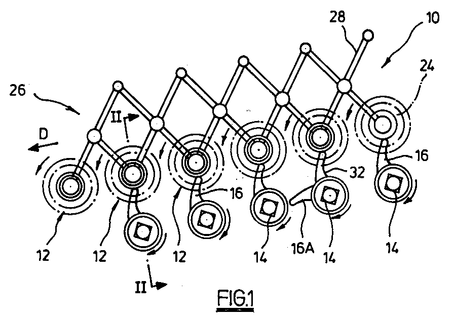
- crop conveying apparatus 10 comprises a series of driveable spiral roller conveyor elements 12 and an associated series of shafts 14 carrying projections 16.
- the projections are mounted adjacent the roller conveyor elements at intervals along the lengths thereof so as to mesh with the spirals to remove material thereform.
- Roller conveyor elements 12 each comprise a spiral element 18 of helical form seen in Fig 2 and driveably mounted on a central shaft 20 and provided with an end plate 22 at each of the opposite axial ends thereof. Between spiral element 18 and shaft 20 there is an otherwise unoccupied space 24 into which projections 16 project.
- a lazy tongs device 26 is provided to adjust the spacing between roller conveyor elements 12.
- the lazy tongs device is actuated by a thrust device (not shown) such as a ram connected to an end actuating arm 28 and provides a convenient means for adjusting the spacing between the rollers whereby the cleaning action which they exert on crop material passing thereover is altered.
- Corresponding adjustment means may be provided for the shafts 14 and their corresponding projections, or not, since the degree of spacial adjustment of the roller conveyor elements 12 need not be so great as to have the result that the movement of the roller conveyor elements extends beyond the zones in which the projections 16 are effective.
- Projections 16 are mounted on the shafts 14 as shown in Fig 2 through individual hubs 30 suitably keyed to the square-section shafts.
- the shafts 14, and indeed the shafts 20, are mounted in end bearings (not shown) and are driveably coupled together by pinions or the like so as to rotate in opposite directions.
- Fig 1 The directions of rotation are indicated in Fig 1 ie the finger 16 rotate in the opposite direction to the roller conveyor elements 12.
- the conveying direction for crop passing over apparatus 10 is indicated by arrow D in Fig 1.
- Projections 16 are in the form of fingers moulded in a resilient material such as natural or synthetic rubber or another suitable polymer. Their general form is seen in Fig 1 in which it can be seen that they are inclined slightly forwards in the direction of rotation so as to have a more aggressive action than if they were of trailing form.
- the leading edge 32 is of concave profile.
- Fingers 16 are disposed at spaced intervals along shaft 14. As shown at 16A in Fig 1, successive ones of the fingers are disposed at angularly offset positions so that the succession of fingers describes a spiral extending around the axis of the respective shaft 14.
- the drive for shafts 14 and 20 is arranged to rotate these shafts at different speeds.
- the shafts 14 rotate at a lower rate of rotation than the shafts 20, preferably in the range from 5 to 30% slower, and optimally between 7.5% and 12.5% slower.
- the projections progressively act on successive portions of the spiral periphery of the elements 18.
- the axis of shafts 14 and 20 are generally parallel.
- crop material is conveyed in direction D over the roller conveyor elements 12. Unwanted material passes between successive roller elements through the gaps.
- the fingers 16 could rotate in the same direction as the rollers 12, but the cleaning action would be expected to be less effective.
- the form and number of such fingers could be varied considerably, and likewise the choice of material therefore is open to considerable variation.
- the fingers 16 could be arranged to be rotated by the rotary action of the spiral elements 18 themselves. In such a case, the axes of rotation of the fingers would probably need to be adjusted from the parallel relationship shown in the drawings to a somewhat different disposition.
- the fingers 16 could be moulded or otherwise formed and in some circumstances it might be desirable to provide more than one such projection or finger at any one given axial location.
- shafts 114 are of hexagonal section. This polygonal form permits simpler indexing of the fingers around the shaft for assembly purposes.
- fingers 116 are constructed to have a trailing profile with respect to their direction of rotation so as to have a less aggressive cleaning action. It has been found that this is to be preferred in many instances, particularly with respect to many types of potato crop.
Landscapes
- Life Sciences & Earth Sciences (AREA)
- Environmental Sciences (AREA)
- Engineering & Computer Science (AREA)
- Mechanical Engineering (AREA)
- Apparatuses For Bulk Treatment Of Fruits And Vegetables And Apparatuses For Preparing Feeds (AREA)
Abstract
Description
- This invention relates to a method and apparatus for conveying or cleaning crop or the like. An example of the use of the invention is the cleaning of a harvested potato crop. The invention may find application to many other such crops and may be used in crop and the like conveyors in any situation where it is desired to remove soil or crop material or other material from conveyor elements. One application of the invention would be for use in a potato or like crop harvester.
- Prior disclosures to which attention is drawn include :
US-A-2,261,893 (Wolfard), GB-A-754,400 (Christensen), EP-A-0, 410,807 (Pearson), GB-A-2,232,866 (Pearson) and GB-A-2,222,507 (Pearson). - None of the above specifications provides any relevant teaching in relation to the cleaning of spiral roller conveyor elements in crop or the like conveying apparatus.
- In the case of crop or the like conveying apparatus employing driveable spiral roller conveyor elements the problem arises that soil and other waste material tends to become lodged or to accumulate in or on the spirals of the conveyor elements and as a result efficiency of the conveyor and the effectiveness of its cleaning action is reduced. We have identified a need for improvements in this respect, or generally.
- According to the invention there is provided crop or the like conveying or cleaning apparatus and a method of conveying or cleaning crop or the like as defined in the accompanying claims.
- In an embodiment of the invention there is provided crop or the like conveying apparatus in which driveable spiral roller conveyor elements are each provided with a plurality of projections mounted adjacent these conveyor elements at intervals along the length thereof so as to mesh with the spirals to remove material therefrom. In this way a convenient cleaning action is performed on the roller conveyor elements.
- Likewise in the embodiment, the projections are mounted on a shaft, arranged to be rotated and driven in the opposite direction to the roller conveyor elements and are constructed of a resilient material. In this way the projections are provided with a simple means for giving them the necessary positive cleaning action. This is accentuated by the opposite direction of rotation of the projections. Moreover, provision of these in resilient form enables them to snap or click-over successive portions of the spiral rotating conveyor elements as cleaning progresses. This action has an inherent cleaning effect on the co-operating parts and contributes to the overall cleaning effect.
- In the embodiment, the projections are disposed spirally about the axes of rotation of the shaft-mounting thereof. In this way a progressive cleaning action is provided which can be disposed in a somewhat timed relationship to the helical or spiral turns of the roller conveyor element in question. The drive for the projections may be arranged to rotate them at from 5 to 30% slower than the roller conveyor elements, and preferably at 7.5% to 12.5% slower. As a result of this speed differential, the projections have a progressive cleaning action on successive portions of the spiral structure.
- Also in the embodiment, the projections have a finger-like form with an inclined or leading inclination having regard to their direction of rotation, thereby producing a somewhat aggressive cleaning action. This can be considered as resulting in the foreign matter being picked out from the roller rather than being pushed inwards.
- As regards the outward or radial extent of the projections from their shaft or other mounting, this is arranged in relation to the roller conveyor elements so that the projections extend into the spiral form thereof by an amount such that they enter the space between the spiral element itself but do not quite reach the central shaft thereof.
- An embodiment of the invention will now be described by way of example with reference to the accompanying drawings in which :
- Fig 1 shows a side elevation view of a portion of crop or the like conveying apparatus comprising a series of spiral roller conveyor elements mounted on a lazy tongs device and a series of co-operating shafts carrying projections;
- Fig 2 shows a section through the apparatus of Fig 1 taken on the line II-II showing a portion of the axial length of the apparatus including one of said projections and the corresponding portion of the spiral roller conveyor element; and
- Fig 3 shows a modification of the embodiment of Fig 2.
- As shown in the drawings
crop conveying apparatus 10 comprises a series of driveable spiralroller conveyor elements 12 and an associated series ofshafts 14 carryingprojections 16. The projections are mounted adjacent the roller conveyor elements at intervals along the lengths thereof so as to mesh with the spirals to remove material thereform. -
Roller conveyor elements 12 each comprise aspiral element 18 of helical form seen in Fig 2 and driveably mounted on acentral shaft 20 and provided with anend plate 22 at each of the opposite axial ends thereof. Betweenspiral element 18 andshaft 20 there is an otherwiseunoccupied space 24 into whichprojections 16 project. - A
lazy tongs device 26 is provided to adjust the spacing betweenroller conveyor elements 12. The lazy tongs device is actuated by a thrust device (not shown) such as a ram connected to an end actuatingarm 28 and provides a convenient means for adjusting the spacing between the rollers whereby the cleaning action which they exert on crop material passing thereover is altered. Corresponding adjustment means may be provided for theshafts 14 and their corresponding projections, or not, since the degree of spacial adjustment of theroller conveyor elements 12 need not be so great as to have the result that the movement of the roller conveyor elements extends beyond the zones in which theprojections 16 are effective. -
Projections 16 are mounted on theshafts 14 as shown in Fig 2 throughindividual hubs 30 suitably keyed to the square-section shafts. Theshafts 14, and indeed theshafts 20, are mounted in end bearings (not shown) and are driveably coupled together by pinions or the like so as to rotate in opposite directions. - The directions of rotation are indicated in Fig 1 ie the
finger 16 rotate in the opposite direction to theroller conveyor elements 12. The conveying direction for crop passing overapparatus 10 is indicated by arrow D in Fig 1. -
Projections 16 are in the form of fingers moulded in a resilient material such as natural or synthetic rubber or another suitable polymer. Their general form is seen in Fig 1 in which it can be seen that they are inclined slightly forwards in the direction of rotation so as to have a more aggressive action than if they were of trailing form. The leadingedge 32 is of concave profile. -
Fingers 16 are disposed at spaced intervals alongshaft 14. As shown at 16A in Fig 1, successive ones of the fingers are disposed at angularly offset positions so that the succession of fingers describes a spiral extending around the axis of therespective shaft 14. - The drive for
shafts shafts 14 rotate at a lower rate of rotation than theshafts 20, preferably in the range from 5 to 30% slower, and optimally between 7.5% and 12.5% slower. By virtue of the difference in speed of rotation, the projections progressively act on successive portions of the spiral periphery of theelements 18. The axis ofshafts - In use, crop material is conveyed in direction D over the
roller conveyor elements 12. Unwanted material passes between successive roller elements through the gaps. - As the roller conveyor elements rotate,
fingers 16 mesh therewith in a contra-rotating action. As the fingers pass through the rotatingspiral elements 18, the screwing action of the latter causes the fingers to be deflected more and more until each one is obliged to click or snap over the spiral element into the next gap therein. As the fingers pass through the helix of the spiral element they exert a significant cleaning action. - Amongst other modifications which could be made in the above embodiment are the following. Firstly, the
fingers 16 could rotate in the same direction as therollers 12, but the cleaning action would be expected to be less effective. Secondly, the form and number of such fingers could be varied considerably, and likewise the choice of material therefore is open to considerable variation. If desired, thefingers 16 could be arranged to be rotated by the rotary action of thespiral elements 18 themselves. In such a case, the axes of rotation of the fingers would probably need to be adjusted from the parallel relationship shown in the drawings to a somewhat different disposition. Thefingers 16 could be moulded or otherwise formed and in some circumstances it might be desirable to provide more than one such projection or finger at any one given axial location. - In the embodiment of Fig 3 all details of the construction and arrangement are otherwise substantially as described above, and therefore will not be repeated, except as follows.
- In this embodiment, parts corresponding to those of Figs 1 and 2 have the same reference numerals, but increased by 100. Thus, projections or
fingers 16 become 116 etc. - In this embodiment,
shafts 114 are of hexagonal section. This polygonal form permits simpler indexing of the fingers around the shaft for assembly purposes. - As regards the
fingers 116, it will be noted that these are constructed to have a trailing profile with respect to their direction of rotation so as to have a less aggressive cleaning action. It has been found that this is to be preferred in many instances, particularly with respect to many types of potato crop.
Claims (14)
- Crop or the like conveying or cleaning apparatus comprising at least one driveable spiral roller conveyor element, characterised by a plurality of projections mounted adjacent said roller conveyor element at intervals along the length thereof so as to mesh or co-operate with said spiral to remove material therefrom.
- Apparatus according to claim 1 characterised by said projections being mounted on a shaft.
- Apparatus according to claim 1 or claim 2 characterised by said projections being arranged to be rotated.
- Apparatus according to any one of claims 1 to 4 characterised by drive means for said projections.
- Apparatus according to claim 4 characterised by said drive being adapted to rotate said projections in the opposite direction to the direction of rotation of said roller conveyor element.
- Apparatus according to claim 3 characterised by the axes of rotation of said projections and of said roller conveyor element being disposed generally parallel to each other.
- Apparatus according to claim 3 characterised by said projections being disposed spirally about the axes of rotation of said shaft.
- Apparatus according to claim 4 characterised by said drive being adapted to rotate said projections at a different speed from the rate of rotation of said roller conveyor element.
- Apparatus according to claim 8 characterised by said drive being adapted to rotate said projections at a speed of from 5% to 30% slower than said roller conveyor element.
- Apparatus according to any one of the preceding claims characterised by said projections being resilient.
- Apparatus according to any one of the preceding claims characterised by said projections being of finger-like form.
- Apparatus according to claim 11 characterised by said fingers being inclined rearwards with respect to their own direction of rotation.
- Apparatus according to any one of the preceding claims characterised by a plurality of said roller conveyor elements disposed alongside each other to provide said conveying apparatus and each having its own series of said projections mounted to mesh with the spiral roller conveyor element thereof.
- A method of conveying crop or the like comprising driving a spiral roller conveyor element, mounting a plurality of projections adjacent said roller conveyor element at intervals along the length thereof and causing said projections to mesh with said spiral so as to remove material therefrom.
Priority Applications (2)
| Application Number | Priority Date | Filing Date | Title |
|---|---|---|---|
| EP19940301886 EP0673593B1 (en) | 1994-03-16 | 1994-03-16 | Method and apparatus for conveying crop or the like |
| DE69412786T DE69412786D1 (en) | 1994-03-16 | 1994-03-16 | Method and device for conveying minced fruit |
Applications Claiming Priority (1)
| Application Number | Priority Date | Filing Date | Title |
|---|---|---|---|
| EP19940301886 EP0673593B1 (en) | 1994-03-16 | 1994-03-16 | Method and apparatus for conveying crop or the like |
Publications (2)
| Publication Number | Publication Date |
|---|---|
| EP0673593A1 true EP0673593A1 (en) | 1995-09-27 |
| EP0673593B1 EP0673593B1 (en) | 1998-08-26 |
Family
ID=8217615
Family Applications (1)
| Application Number | Title | Priority Date | Filing Date |
|---|---|---|---|
| EP19940301886 Expired - Lifetime EP0673593B1 (en) | 1994-03-16 | 1994-03-16 | Method and apparatus for conveying crop or the like |
Country Status (2)
| Country | Link |
|---|---|
| EP (1) | EP0673593B1 (en) |
| DE (1) | DE69412786D1 (en) |
Cited By (7)
| Publication number | Priority date | Publication date | Assignee | Title |
|---|---|---|---|---|
| NL1016090C2 (en) * | 2000-09-04 | 2002-03-05 | Miedema Landbouwwerktuigen | Device for separating tare from agricultural products and method for cleaning this device. |
| WO2003026384A1 (en) * | 2001-09-26 | 2003-04-03 | Richard Pearson Limited | An agricultural separator |
| EP2050326A1 (en) * | 2007-10-19 | 2009-04-22 | Grimme Landmaschinenfabrik GmbH & Co. KG | Transport and dividing device for root crops and corresponding method |
| CN103918362A (en) * | 2014-04-29 | 2014-07-16 | 吉林大学 | Profiling bionic press roller |
| EP2997807A1 (en) | 2014-09-16 | 2016-03-23 | Bijlsma Hercules BV | Device for cleaning, sieving and (pre)sorting of bulbous plants, tuberous plants and root crop |
| CN110639789A (en) * | 2019-09-11 | 2020-01-03 | 新昌县彭诚农业科技有限公司 | Elastic rod sieve plate for sticky wet coal automatically cleaned by using speed difference |
| CN114793597A (en) * | 2022-05-05 | 2022-07-29 | 承德万联机械制造有限公司 | Onion harvester and using method thereof |
Families Citing this family (1)
| Publication number | Priority date | Publication date | Assignee | Title |
|---|---|---|---|---|
| CN114247635A (en) * | 2021-12-30 | 2022-03-29 | 太原科技大学 | Vibrating screen with adjustable screen holes |
Citations (7)
| Publication number | Priority date | Publication date | Assignee | Title |
|---|---|---|---|---|
| GB857827A (en) * | 1956-07-09 | 1961-01-04 | Lely Nv C Van Der | Improvements in or relating to devices for lifting tubers, potatoes, beets and like crops from the soil |
| DE1169183B (en) * | 1958-06-10 | 1964-04-30 | Massey Ferguson Great Britain | Cleaning device for conveyors on or in root crop harvesting machines |
| BE861618A (en) * | 1977-12-08 | 1978-03-31 | Buttering Maschf Geb | ROLLER SHELF FOR CLEANING AGRICULTURAL PRODUCTS, IN PARTICULAR SUGAR BEET |
| GB2017536A (en) * | 1978-03-17 | 1979-10-10 | Grimme Landmaschf Franz | Separating apparatus |
| FR2520334A1 (en) * | 1982-01-27 | 1983-07-29 | Vuillafans Expl Usines | Self cleaning device for worm screw in conveyor mixer etc. - employs returnable scraper blades driven along between screw spirals |
| EP0280399A2 (en) * | 1987-01-26 | 1988-08-31 | Flexi-Coil (Uk) Limited | Coil apparatus |
| EP0294903A1 (en) * | 1987-06-10 | 1988-12-14 | C. van der Lely N.V. | A soil cultivating machine comprising a roller |
-
1994
- 1994-03-16 EP EP19940301886 patent/EP0673593B1/en not_active Expired - Lifetime
- 1994-03-16 DE DE69412786T patent/DE69412786D1/en not_active Expired - Lifetime
Patent Citations (7)
| Publication number | Priority date | Publication date | Assignee | Title |
|---|---|---|---|---|
| GB857827A (en) * | 1956-07-09 | 1961-01-04 | Lely Nv C Van Der | Improvements in or relating to devices for lifting tubers, potatoes, beets and like crops from the soil |
| DE1169183B (en) * | 1958-06-10 | 1964-04-30 | Massey Ferguson Great Britain | Cleaning device for conveyors on or in root crop harvesting machines |
| BE861618A (en) * | 1977-12-08 | 1978-03-31 | Buttering Maschf Geb | ROLLER SHELF FOR CLEANING AGRICULTURAL PRODUCTS, IN PARTICULAR SUGAR BEET |
| GB2017536A (en) * | 1978-03-17 | 1979-10-10 | Grimme Landmaschf Franz | Separating apparatus |
| FR2520334A1 (en) * | 1982-01-27 | 1983-07-29 | Vuillafans Expl Usines | Self cleaning device for worm screw in conveyor mixer etc. - employs returnable scraper blades driven along between screw spirals |
| EP0280399A2 (en) * | 1987-01-26 | 1988-08-31 | Flexi-Coil (Uk) Limited | Coil apparatus |
| EP0294903A1 (en) * | 1987-06-10 | 1988-12-14 | C. van der Lely N.V. | A soil cultivating machine comprising a roller |
Cited By (11)
| Publication number | Priority date | Publication date | Assignee | Title |
|---|---|---|---|---|
| NL1016090C2 (en) * | 2000-09-04 | 2002-03-05 | Miedema Landbouwwerktuigen | Device for separating tare from agricultural products and method for cleaning this device. |
| EP1183930A1 (en) * | 2000-09-04 | 2002-03-06 | Miedema Landbouwwerktuigenfabriek B.V. | Device for separating tare from agricultural products and method for cleaning said device |
| WO2003026384A1 (en) * | 2001-09-26 | 2003-04-03 | Richard Pearson Limited | An agricultural separator |
| EP2050326A1 (en) * | 2007-10-19 | 2009-04-22 | Grimme Landmaschinenfabrik GmbH & Co. KG | Transport and dividing device for root crops and corresponding method |
| US8191714B2 (en) | 2007-10-19 | 2012-06-05 | Grimme Landmaschinenfabrik Gmbh & Co. Kg | Conveying and separating device for root crop and a method for operating the device |
| CN103918362A (en) * | 2014-04-29 | 2014-07-16 | 吉林大学 | Profiling bionic press roller |
| EP2997807A1 (en) | 2014-09-16 | 2016-03-23 | Bijlsma Hercules BV | Device for cleaning, sieving and (pre)sorting of bulbous plants, tuberous plants and root crop |
| NL2013477B1 (en) * | 2014-09-16 | 2016-09-28 | Bijlsma Hercules B V | Device for cleaning, sieving and (pre) sorting bulb, tuber, and root crops. |
| CN110639789A (en) * | 2019-09-11 | 2020-01-03 | 新昌县彭诚农业科技有限公司 | Elastic rod sieve plate for sticky wet coal automatically cleaned by using speed difference |
| CN114793597A (en) * | 2022-05-05 | 2022-07-29 | 承德万联机械制造有限公司 | Onion harvester and using method thereof |
| CN114793597B (en) * | 2022-05-05 | 2023-03-24 | 承德万联机械制造有限公司 | Onion harvester and using method thereof |
Also Published As
| Publication number | Publication date |
|---|---|
| EP0673593B1 (en) | 1998-08-26 |
| DE69412786D1 (en) | 1998-10-01 |
Similar Documents
| Publication | Publication Date | Title |
|---|---|---|
| US8191714B2 (en) | Conveying and separating device for root crop and a method for operating the device | |
| EP0673593A1 (en) | Method and apparatus for conveying crop or the like | |
| CN104475375B (en) | Rhizoma Solani tuber osi separating conveyor cleaning plant | |
| US5919086A (en) | Combine rotor and method | |
| CA2129588C (en) | Stone separation table for potatoes and other root crops | |
| WO1988004885A1 (en) | Apparatus and method for harvesting crops | |
| US6253535B1 (en) | Finger rollers for agricultural implements | |
| CN113207408B (en) | Drum screen device of cyperus esculentus harvester | |
| CA2282630C (en) | Apparatus and method for removing tops or roots from crops | |
| GB2274380A (en) | Crop conveying apparatus | |
| CA2156406C (en) | Beansprouts roots and husks cleaning machine | |
| EP0907426B1 (en) | Agricultural separating device and starwheel scrapers | |
| CN111226566B (en) | A kind of Jerusalem artichoke tuber cleaning device for Jerusalem artichoke combine harvester | |
| US20200296886A1 (en) | Cleaning device for cleaning crops as well as harvesting machine | |
| EP1661471A1 (en) | Separating and transferring device for tuberous products | |
| EP0557702A2 (en) | Transversal screw conveyor for a mowing or maize-harvesting attachment | |
| CN216313946U (en) | Auger and scattering machine | |
| WO2001015821A1 (en) | Separating device | |
| FI87186B (en) | SKRUVGALLER. | |
| SU1015847A1 (en) | Cleaning separator | |
| JP2021136907A (en) | Mud removal device of crop | |
| JPH088600Y2 (en) | Lower leaf remover in flower sorter | |
| SU1750469A1 (en) | Device for separating off sold and plant residues from potato tubers | |
| CN107855283A (en) | A kind of seed pin type separator | |
| DE2730877C2 (en) | Conveying and cleaning device on beet harvesting machines |
Legal Events
| Date | Code | Title | Description |
|---|---|---|---|
| PUAI | Public reference made under article 153(3) epc to a published international application that has entered the european phase |
Free format text: ORIGINAL CODE: 0009012 |
|
| 17P | Request for examination filed |
Effective date: 19950213 |
|
| AK | Designated contracting states |
Kind code of ref document: A1 Designated state(s): BE DE FR GB NL |
|
| 17Q | First examination report despatched |
Effective date: 19960614 |
|
| GRAG | Despatch of communication of intention to grant |
Free format text: ORIGINAL CODE: EPIDOS AGRA |
|
| GRAG | Despatch of communication of intention to grant |
Free format text: ORIGINAL CODE: EPIDOS AGRA |
|
| GRAH | Despatch of communication of intention to grant a patent |
Free format text: ORIGINAL CODE: EPIDOS IGRA |
|
| GRAH | Despatch of communication of intention to grant a patent |
Free format text: ORIGINAL CODE: EPIDOS IGRA |
|
| GRAA | (expected) grant |
Free format text: ORIGINAL CODE: 0009210 |
|
| RBV | Designated contracting states (corrected) |
Designated state(s): BE DE FR GB NL |
|
| AK | Designated contracting states |
Kind code of ref document: B1 Designated state(s): BE DE FR GB NL |
|
| PG25 | Lapsed in a contracting state [announced via postgrant information from national office to epo] |
Ref country code: NL Free format text: LAPSE BECAUSE OF FAILURE TO SUBMIT A TRANSLATION OF THE DESCRIPTION OR TO PAY THE FEE WITHIN THE PRESCRIBED TIME-LIMIT Effective date: 19980826 Ref country code: FR Free format text: LAPSE BECAUSE OF FAILURE TO SUBMIT A TRANSLATION OF THE DESCRIPTION OR TO PAY THE FEE WITHIN THE PRESCRIBED TIME-LIMIT Effective date: 19980826 Ref country code: BE Free format text: LAPSE BECAUSE OF FAILURE TO SUBMIT A TRANSLATION OF THE DESCRIPTION OR TO PAY THE FEE WITHIN THE PRESCRIBED TIME-LIMIT Effective date: 19980826 |
|
| REF | Corresponds to: |
Ref document number: 69412786 Country of ref document: DE Date of ref document: 19981001 |
|
| PG25 | Lapsed in a contracting state [announced via postgrant information from national office to epo] |
Ref country code: DE Free format text: LAPSE BECAUSE OF FAILURE TO SUBMIT A TRANSLATION OF THE DESCRIPTION OR TO PAY THE FEE WITHIN THE PRESCRIBED TIME-LIMIT Effective date: 19981127 |
|
| EN | Fr: translation not filed | ||
| NLV1 | Nl: lapsed or annulled due to failure to fulfill the requirements of art. 29p and 29m of the patents act | ||
| PGFP | Annual fee paid to national office [announced via postgrant information from national office to epo] |
Ref country code: GB Payment date: 19990318 Year of fee payment: 6 |
|
| PLBE | No opposition filed within time limit |
Free format text: ORIGINAL CODE: 0009261 |
|
| STAA | Information on the status of an ep patent application or granted ep patent |
Free format text: STATUS: NO OPPOSITION FILED WITHIN TIME LIMIT |
|
| 26N | No opposition filed | ||
| PG25 | Lapsed in a contracting state [announced via postgrant information from national office to epo] |
Ref country code: GB Free format text: LAPSE BECAUSE OF NON-PAYMENT OF DUE FEES Effective date: 20000316 |
|
| GBPC | Gb: european patent ceased through non-payment of renewal fee |
Effective date: 20000316 |