EP0673136B1 - Verfahren und Schaltungsanordnung zum Steuern der Übertragung von Nachrichtenblöcken innerhalb eines Übertragungssystems - Google Patents
Verfahren und Schaltungsanordnung zum Steuern der Übertragung von Nachrichtenblöcken innerhalb eines Übertragungssystems Download PDFInfo
- Publication number
- EP0673136B1 EP0673136B1 EP95102017A EP95102017A EP0673136B1 EP 0673136 B1 EP0673136 B1 EP 0673136B1 EP 95102017 A EP95102017 A EP 95102017A EP 95102017 A EP95102017 A EP 95102017A EP 0673136 B1 EP0673136 B1 EP 0673136B1
- Authority
- EP
- European Patent Office
- Prior art keywords
- message blocks
- transmission
- stipulated
- processor
- queue
- Prior art date
- Legal status (The legal status is an assumption and is not a legal conclusion. Google has not performed a legal analysis and makes no representation as to the accuracy of the status listed.)
- Expired - Lifetime
Links
- 230000005540 biological transmission Effects 0.000 title claims description 77
- 238000000034 method Methods 0.000 title claims description 11
- 230000000737 periodic effect Effects 0.000 claims description 2
- 241001484259 Lacuna Species 0.000 claims 1
- 230000008878 coupling Effects 0.000 description 3
- 238000010168 coupling process Methods 0.000 description 3
- 238000005859 coupling reaction Methods 0.000 description 3
- 101150096620 LAE1 gene Proteins 0.000 description 1
- 230000006978 adaptation Effects 0.000 description 1
- 238000006243 chemical reaction Methods 0.000 description 1
- 238000001514 detection method Methods 0.000 description 1
- 230000001771 impaired effect Effects 0.000 description 1
- 230000004044 response Effects 0.000 description 1
Images

Classifications
-
- H—ELECTRICITY
- H04—ELECTRIC COMMUNICATION TECHNIQUE
- H04L—TRANSMISSION OF DIGITAL INFORMATION, e.g. TELEGRAPHIC COMMUNICATION
- H04L47/00—Traffic control in data switching networks
- H04L47/10—Flow control; Congestion control
- H04L47/30—Flow control; Congestion control in combination with information about buffer occupancy at either end or at transit nodes
-
- H—ELECTRICITY
- H04—ELECTRIC COMMUNICATION TECHNIQUE
- H04L—TRANSMISSION OF DIGITAL INFORMATION, e.g. TELEGRAPHIC COMMUNICATION
- H04L47/00—Traffic control in data switching networks
- H04L47/10—Flow control; Congestion control
-
- H—ELECTRICITY
- H04—ELECTRIC COMMUNICATION TECHNIQUE
- H04L—TRANSMISSION OF DIGITAL INFORMATION, e.g. TELEGRAPHIC COMMUNICATION
- H04L47/00—Traffic control in data switching networks
- H04L47/10—Flow control; Congestion control
- H04L47/26—Flow control; Congestion control using explicit feedback to the source, e.g. choke packets
Definitions
- the invention relates to a method and a circuit arrangement to control the transmission of message blocks within a transmission system according to the preamble of the claim 1.
- W open window size
- the message blocks that are initially not transferable as a result are placed in one of the relevant line queues assigned reset queue inserted.
- the transmission then of message blocks that are in the relevant line queue are to be inserted by the respective switching computer resumed here, initially taking into account those in the reset queue inserted message blocks.
- the aforementioned tax measures for the transmission of message blocks between switching computers and line connection facilities therefore represent a control system depends in particular on the size of the previously mentioned line queues on the total running time of the control loop.
- the control loop consists of sending out a message block, the detection of an overload in one of the line queues, the return of a corresponding one Control signal and from the response of the switching computer on such a control signal. From this, if necessary relatively long runtimes and memory sizes result, which are sometimes undesirable.
- the invention has the advantage that the load of the individual interfaces through supplied message blocks exclusively in the respective transmission processor is determined and therefore no the runtime of the control loop influencing communications between each Transmission processor and the associated line connection device required are. Another advantage is that at the individual interfaces a Line connection device none in the prior art provided line queues corresponding storage arrangements required are.
- the task outlined above is in a circuit arrangement according to the preamble of claim 5 by the circuitry specified in this claim Features resolved.
- the advantage of the invention is the low circuit complexity for that exclusively realized in the respective transmission processor Control system for the transmission of message blocks between this transmission processor and the associated one Line unit.
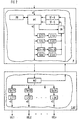
- FIG. 1 schematically shows a transmission system, which has a plurality m of identical transmission processor units P1 ... Pm. These transfer processor units stand out on the one hand a coupling device KE and on the other hand each with a Line connection device in connection. These line connection devices, to each of which a plurality n of Transmission lines UEL1 ... UELn are connected according to the assignment to the transmission processor units designated with LAE1 ... LAEm.
- the transmission system may designed for example as a packet transmission system be, with the coupling device KE for example around one or more interconnected switching devices, around one or more "cross-connect" devices or may be a loop system.
- FIG. 2 shows a possible structure of one of those shown in FIG. 1 Transfer processor units and an associated Line connection device shown in sections.
- the transmission processor unit is P, the line connection device, however, designated LAE. Only those elements are specified in this FIG necessary for the explanation of the present invention are.
- the transfer processor unit P has one for the Control the recording and forwarding of message packets serving processor PR, which among other things with a Packet store M1 is connected.
- this packet store become that of the transmission processor unit with a transmission rate V1 via the coupling device indicated in FIG. 1 KE supplied message packets added.
- the package store serves as a packet queue, i.e. as speed adjustment memory, around the message packets with a lower transmission rate than the transmission rate V1 V2 to the associated line connection device Forward LAE.
- the line connection device LAE has one packet store also serving as a packet queue M2, for example in the form of a "first-in-first-out" memory from which the supplied message packets in accordance with the address information contained therein on the transmission lines shown in FIG 1 UEL1 ... UELn can be distributed. It is assumed that the message blocks over the respective transmission line forwarded with an approximately constant discharge rate V3 be lower than the transfer rate V2 is.
- the line connection device LAE is for each Transmission lines UEL1 ... UELn a separate interface provided, for example, from a buffer Sp for protocol implementation and an adaptation module L is formed. The assignment to the respective transmission line goes from a parenthesized Reference signs.
- a flow control in the present embodiment provided that is designed in two stages. According to one first, global flow control is in the line connection facility LAE constantly the filling level of the packet memory M2 monitored and when a defined threshold value is reached a control signal indicating an overload by the packet memory M2 to a global control device shown in FIG ST-G transmitted. Under the control of this Control device is then the delivery of message packets prevented by the packet memory M1. That way ensures that all message packets in the transmission processor unit P processed and to the line connection device LAE are actually sent to forwarded the transmission lines in question become. This is particularly important if the of message packets delivered to the packet memory M1 the processor will be charged.
- the interfaces and thus the transmission lines individually assigned selection facilities connected, according to their assignment to the Transmission lines UEL1 ... UELn designated S (1) ... S (n) are.
- the respective selection device is one Downstream counter arrangement, the counting range with regard the minimum and maximum meter reading is. For example, it can be an up-down counter act, the minimum count of which Counter reading is "0".
- the individual counter arrangements are in 2 according to their assignment to the selection devices denoted by S (1) ... S (n) by Z (1) ... Z (n).
- the respective selection device is designed such that through this the assigned interface (Transmission line) to be supplied message packets the address information contained therein and the current one Counter reading of the associated counter arrangement by one corresponding to the packet length of the respective message packet Count value is incremented. You can do this, for example in the event that message packets within the transmission system are transmitted with a variable packet length, those contained in the packet headers of these message packets Information regarding the package length can be used. alternative this can be done by the respective selection device Package length also by counting, for example, that in the respective Message packet contained bytes are determined if no information in the packet headers of the message packets regarding the package length are included and the respective Message packet marked by a start and end identifier is. In addition, in the event that within the Transmission system only message packets with a fixed Packet length are transmitted with every occurrence of a Message packet directly the current counter reading of the respective Counter arrangement by one corresponding to the fixed packet length Incremented count value.
- the counter value by which the current counter reading of a counter arrangement when a Message packet to be incremented is the number of bytes belonging to the respective message packet are used become.
- it can also be a different, proportional to the packet length of the respective message packet specified count value can be used.
- the respective counter arrangement Z (1) ... Z (n) at periodic intervals by one of the discharge rates of the message packets on the respective transmission line decremented the corresponding count value. Again, either the number of bytes flowing out per time interval or a proportional size is used.
- the control outputs of the counter arrangements Z (1) ... Z (n) are at the present embodiment together to a release device FR connected, which additionally from the Packet memory M1 forth a release signal indicating its fill level is fed.
- a fed to the release device FR control signal indicating an overload of an interface only becomes an interface-related one Control device ST-S forwarded when through that called release signal a above a specified
- the filling level of the packet memory M1 lying below the threshold value is displayed is.
- the forwarding of message packets to the respective Transmission line UEL1 ... UELn prevented, i.e. the message packets intended for this transmission line are discarded.
- Through this targeted release of one Control signals indicating overload are achieved that message packets only be discarded if the degree of filling of the packet memory M1 exceeds the defined threshold.
- the for the interface-related Flow control facilities also provided can be modified such that instead of the selection devices S (1) ... S (n) one in multiplex mode exploited selection device can be provided, which in accordance with those contained in the message packages Address information for the respective message package selected meter arrangement and thereby their current meter reading incremented in the manner specified above.
- control device ST-S can also be used for identification of a meter arrangement Z (1) ... Z (n) by the control device ST-S a respective meter arrangement and thus the assigned interface Address information indicative of (transmission line) together with a control signal indicating an overload via the release device FR to the control device ST-S be delivered.
- these control signals can be used also individually assigned lines above the meter arrangements are transmitted to the control device ST-S.
- the counter arrangements mentioned can depend on the Transfer rates either software or hardware, for example in the form of counter modules or a programmable one Logic, be realized.
Landscapes
- Engineering & Computer Science (AREA)
- Computer Networks & Wireless Communication (AREA)
- Signal Processing (AREA)
- Data Exchanges In Wide-Area Networks (AREA)
Description
- FIG 1
- zeigt in schematischer Form ein Übertragungssystem, bei welchem die Erfindung angewandt ist, und
- FIG 2
- zeigt ausschnittweise einen möglichen Aufbau einer der in FIG 1 lediglich schematisch dargestellten Übertragungsprozessor-Einheiten sowie einer damit verbundenen Leitungsanschlußeinrichtung.
Claims (10)
- Verfahren zum Steuern der Übertragung von Nachrichtenblöcken innerhalb eines Übertragungssystems, welches über miteinander verbundene Übertragungsprozessoren (P) verfügt, von welchen aus jeweils die für diese bestimmten Nachrichtenblöcke nach Durchlauf einer Prozessorwarteschlange (M1) mit einer festgelegten Übertragungsrate (V2) an eine individuell zugeordnete Leitungsanschlußeinrichtung (LAE) weitergeleitet werden, die über eine Mehrzahl von Schnittstellen verfügt, mit denen jeweils eine für die Weiterleitung von Nachrichtenblöcken mit einer gegenüber der festgelegten Übertragungsrate (V2) niedrigeren Abflußrate (V3) ausgelegte Übertragungsleitung (UEL) verbunden ist, wobei die die Prozessorwarteschlange (M1) verlassenden Nachrichtenblöcke jeweils über eine Adressinformation verfügen, durch welche die für die Weiterleitung in Frage kommende Schnittstelle bezeichnet ist,
dadurch gekennzeichnet,daß in dem jeweiligen Übertragungsprozessor (P) individuell für die einzelnen zugeordneten Schnittstellen nach Maßgabe der Anzahl der pro Zeiteinheit an diese jeweils weitergeleiteten Nachrichtenblöcke und der Abflußrate (V3) ein momentaner Lastwert ermittelt wird, unddaß bei Überschreiten eines festgelegten Grenzwertes durch den für eine der Schnittstellen ermittelten momentanen Lastwert die Abgabe von Nachrichtenblöcken an die jeweilige Schnittstelle unterbunden wird. - Verfahren nach Anspruch 1,
dadurch gekennzeichnet, daß die an eine Schnittstelle momentan nicht weiterleitbaren Nachrichtenblöcke dann durch den jeweiligen Übertragungsprozessor verworfen werden, wenn die diesem zugehörige Prozessorwarteschlange einen festgelegten Füllgrad überschreitet. - Verfahren nach Anspruch 1 oder 2,
dadurch gekennzeichnet, daß das Übertragungssystem als Paket-vermittelndes System ausgebildet ist, in welchem die Nachrichtenblöcke als Pakete mit variabler Länge übertragen werden, wobei in die Ermittlung eines momentanen Lastwertes neben der Anzahl der pro Zeiteinheit an die jeweilige Eingangswarteschlange abgegebenen Nachrichtenblöcke auch deren Länge mit einbezogen wird. - Verfahren nach Anspruch 1 oder 2,
dadurch gekennzeichnet, daß das Übertragungssystem als paket-vermittelndes System ausgebildet ist, in welchem die Nachrichtenblöcke als Pakete mit einer festen Länge übertragen werden. - Verfahren nach einem der vorstehenden Ansprüche,
dadurch gekennzeichnet, daß die Nachrichtenblöcke an eine Eingangswarteschlange (M2) der individuell zugeordneten Leitungsanschlußeinrichtung weitergeleitet werden, wobei zwischen dem jeweiligen Übertragungsprozessor und der diesem zugeordneten Leitungsanschlußeinrichtung eine Flußsteuerung derart durchgeführt wird, daß durch den Übertragungsprozessor bei Vorliegen eines festgelegten Füllgrades der Eingangswarteschlange die Abgabe von Nachrichtenblöcken an diese bzw. bei einer Überlastung einer der Schnittstellen die Abgabe die dieser zuzuführenden Nachrichtenblöcke unterbunden wird. - Schaltungsanordnung zum Steuern der Übertragung von Nachrichtenblöcken innerhalb eines Übertragungssystems, welches über miteinander verbundenen Übertragungsprozessoren (P) verfügt, von welchen aus jeweils die für diese bestimmten Nachrichtenblöcke nach Durchlauf einer Prozes-sorwarteschlange (M1) mit einer festgelegten Übertragungsrate an eine individuell zugeordnete Leitungsanschlußeinrichtung (LAE) weitergeleitet werden, die über eine Mehrzahl von Schnittstellen verfügt, mit denen jeweils eine für die Weiterleitung von Nachrichtenblöcken mit einer gegenüber der festgelegten Übertragungsrate (V2) niedrigeren Abflußrate (V3) ausgelegte Übertragungsleitung (UEL) verbunden ist, wobei die die Prozessorwarteschlange (M1) verlassenden Nachrichtenblöcke jeweils über eine Adressinformation verfügen, durch welche die für die Weiterleitung in Frage kommende Schnittstelle bezeichnet ist,
dadurch gekennzeichnet,daß in dem jeweiligen Übertragungsprozessor (P) der Prozessorwarteschlange (M1) den Schnittstellen individuell zugeordnete Selektionsmittel (S) nachgeschaltet sind,daß an das jeweilige Selektionsmittel (S) ein Zählmittel (Z) angeschlossen ist, dessen Zählbereich hinsichtlich des minimalen und des maximalen Zählerstandes begrenzt ist, unddaß die Selektionsmittel und die Zählmittel derart miteinander verbunden und ausgebildet sind,daß durch das jeweilige Selektionsmittel die der zugeordneten Schnittstelle zuzuführenden Nachrichtenblöcke anhand der darin enthaltenen Adresseninformation erfaßt und der momentane Zählerstand des zugehörigen Zählmittels um einen der Länge des jeweiligen Nachrichtenblockes entsprechenden Zählwert inkrementiert wird,daß darüber hinaus der momentane Zählerstand dieses Zählmittels in periodischen Zeitabständen um einen der Abflußrate der Nachrichtenblöcke entsprechenden Zählwert dekrementiert wird, unddaß bei Überschreiten eines festgelegten Schwellwertes durch den momentanen Zählerstand ein eine Überlast der jeweiligen Schnittstelle anzeigendes Steuersignal an einem Steuerausgang des Zählmittels bereitgestellt ist. - Schaltungsanordnung nach Anspruch 6,
dadurch gekennzeichnet, daß für den Fall, daß die Nachrichtenblöcke in Form von Paketen mit einer variablen Paketlänge auftreten und in dem jeweiligen Paket zusätzlich zu einer Adresseninformation Angaben bezüglich der Paketlänge enthalten sind, durch das jeweilige Selektionsmittel der momentane Zählerstand des zugehörigen Zählmittels nach Maßgabe dieser Angaben inkrementiert wird. - Schaltungsanordnung nach Anspruch 6,
dadurch gekennzeichnet, daß für den Fall, daß die Nachrichtenblöcke in Form von Paketen mit einer variablen Paketlänge auftreten und in dem jeweiligen Paket neben der Adresseninformation lediglich einer Paketanfangs- und -endekennung enthalten ist, durch das jeweilige Selektionsmittel die Paketlänge anhand der in den Paketen jeweils enthaltenen Paketanfangs- und -endekennung ermittelt und der momentane Zählerstand des zugehörigen Zählmittels nach Maßgabe der ermittelten Paketlänge inkrementiert wird. - Schaltungsanordnung nach einem der Ansprüche 6 bis 8, dadurch gekennzeichnet, daß die Steuerausgänge der Zählmittel gemeinsam an ein Freigabemittel (FR) angeschlossen sind, welchem zusätzlich ein den Füllgrad der dem jeweiligen Übertragungsprozessor zugehörigen Prozessorwarteschlange (M1) anzeigendes Freigabesignal zugeführt ist, wobei ein eine Überlast einer Schnittstelle anzeigendes Steuersignal lediglich dann freigegeben ist, wenn durch das Freigabesignal ein oberhalb eines festgelegten Schwellwertes liegender Füllgrad der Prozessorwarteschlange angezeigt ist.
- Schaltungsanordnung nach einem der Ansprüche 6 bis 9,
dadurch gekennzeichnet, daß für den Fall, daß die Nachrichtenblöcke an eine Eingangswarteschlange (M2) der individuell zugeordneten Leitungsanschlußeinrichtung weitergeleitet werden, zwischen dem jeweiligen Übertragungsprozessor und der diesem zugeordneten Leitungsanschlußeinrichtung eine Flußsteuerung derart vorgesehen und ausgebildet ist, daß in der Leitungsanschlußeinrichtung ständig der Füllgrad der Eingangswarteschlange überwacht und bei Erreichen eines festgelegten Schwellwertes ein eine Überlast anzeigendes Steuersignal zu einer globalen Steuereinrichtung (ST-G) hin übertragen wird, worauf unter Steuerung dieser Steuereinrichtung dann die Abgabe von Nachrichtenblöcken aus der zugeordneten Prozessorwarteschlange (M1) unterbunden wird.
Applications Claiming Priority (2)
| Application Number | Priority Date | Filing Date | Title |
|---|---|---|---|
| DE4405262A DE4405262C1 (de) | 1994-02-18 | 1994-02-18 | Verfahren und Schaltungsanordnung zum Steuern der Übertragung von Nachrichtenblöcken innerhalb eines Übertragungssystems |
| DE4405262 | 1994-02-18 |
Publications (2)
| Publication Number | Publication Date |
|---|---|
| EP0673136A1 EP0673136A1 (de) | 1995-09-20 |
| EP0673136B1 true EP0673136B1 (de) | 2003-08-13 |
Family
ID=6510605
Family Applications (1)
| Application Number | Title | Priority Date | Filing Date |
|---|---|---|---|
| EP95102017A Expired - Lifetime EP0673136B1 (de) | 1994-02-18 | 1995-02-14 | Verfahren und Schaltungsanordnung zum Steuern der Übertragung von Nachrichtenblöcken innerhalb eines Übertragungssystems |
Country Status (3)
| Country | Link |
|---|---|
| US (1) | US5572520A (de) |
| EP (1) | EP0673136B1 (de) |
| DE (2) | DE4405262C1 (de) |
Families Citing this family (10)
| Publication number | Priority date | Publication date | Assignee | Title |
|---|---|---|---|---|
| US5745477A (en) * | 1996-01-25 | 1998-04-28 | Mitsubishi Electric Information Technology Center America, Inc. | Traffic shaping and ABR flow control |
| US5938749A (en) * | 1996-06-03 | 1999-08-17 | Whittaker Communications Inc. | Queue measurement apparatus and methodology |
| US5926457A (en) * | 1996-08-22 | 1999-07-20 | D-Link Corporation | Network controller, and method of calculating the in time interrupt point by means of the application of a fuzzy theory |
| US6098122A (en) * | 1998-03-27 | 2000-08-01 | International Business Machines Corporation | Method and apparatus for adaptively blocking outgoing communication requests and adjusting the blocking factor according to the volume of requests being received in an information handling system |
| JP3558522B2 (ja) | 1998-06-12 | 2004-08-25 | 三菱電機株式会社 | レート制御通信装置及びレート制御通信方法 |
| US20030158883A1 (en) * | 2002-02-04 | 2003-08-21 | Drudis Antoni N. | Message processing |
| KR100429911B1 (ko) * | 2002-05-18 | 2004-05-03 | 한국전자통신연구원 | 가변길이 패킷 다중화 및 역다중화 장치와 방법 |
| DE10225913B4 (de) * | 2002-06-11 | 2005-08-11 | Siemens Ag | Verfahren zur Überlastabwehr |
| US8972455B2 (en) * | 2010-10-19 | 2015-03-03 | Hewlett-Packard Development Company, L.P. | System and method for traffic surge control |
| US9055009B2 (en) * | 2011-12-19 | 2015-06-09 | International Business Machines Corporation | Hybrid arrival-occupancy based congestion management |
Family Cites Families (5)
| Publication number | Priority date | Publication date | Assignee | Title |
|---|---|---|---|---|
| US5119367A (en) * | 1988-10-28 | 1992-06-02 | Oki Electric Industry Co., Ltd. | Method and a node circuit for routing bursty data |
| EP0475180A1 (de) * | 1990-09-04 | 1992-03-18 | Siemens Aktiengesellschaft | Verfahren zum Übertragen von Nachrichtenblöcken zwischen bei bestehenden Verbindungen einander zugeordneten Übertragungsleitungen einer Fernmeldevermittlungsanlage |
| DE4121863C2 (de) * | 1991-07-02 | 1995-12-14 | Siemens Ag | Verfahren und Anordnung zur Überwachung und Vermeidung eines Überlaufs und/oder einer Entleerung eines Pufferspeichers |
| IT1257546B (it) * | 1992-06-15 | 1996-01-30 | Cselt Centro Studi Lab Telecom | Commutatore ottico per reti a commutazione veloce di cella. |
| US5335224A (en) * | 1992-06-30 | 1994-08-02 | At&T Bell Laboratories | Service guarantees/congestion control in high speed networks |
-
1994
- 1994-02-18 DE DE4405262A patent/DE4405262C1/de not_active Expired - Fee Related
-
1995
- 1995-02-13 US US08/387,188 patent/US5572520A/en not_active Expired - Lifetime
- 1995-02-14 EP EP95102017A patent/EP0673136B1/de not_active Expired - Lifetime
- 1995-02-14 DE DE59510761T patent/DE59510761D1/de not_active Expired - Fee Related
Also Published As
| Publication number | Publication date |
|---|---|
| EP0673136A1 (de) | 1995-09-20 |
| DE4405262C1 (de) | 1995-11-09 |
| US5572520A (en) | 1996-11-05 |
| DE59510761D1 (de) | 2003-09-18 |
Similar Documents
| Publication | Publication Date | Title |
|---|---|---|
| DE3587092T2 (de) | Kommunikationssystem. | |
| DE69420408T2 (de) | ATM-Übermittlungssystem zur statistischen Multiplexbildung von Zellen | |
| DE60120807T2 (de) | Schaltvorrichtung und Verfahren | |
| DE69732398T2 (de) | System zur Verkehrssteuerung und Überlastregelung für Paketnetzwerke | |
| DE19634492B4 (de) | Verfahren zum optimierten Übertragen von ATM-Zellen über Verbindungsabschnitte | |
| DE602004006573T2 (de) | Erzeugen eines schmalbandigen Kanals innerhalb einer breitbandigen Paketübertragung | |
| DE19507570C2 (de) | Verfahren und Schaltungsanordnung zum Weiterleiten von über eine ATM-Kommunikationseinrichtung übertragenen Nachrichtenzellen an eine Abnehmerleitung | |
| EP0419959B1 (de) | Schaltungsanordnung zum Überprüfen der Einhaltung festgelegter Übertragungsbitraten bei der Übertragung von Nachrichtenzellen | |
| EP0645919A2 (de) | Verfahren zum Übertragen von Nachrichtenzellen über redundante virtuelle Pfadpaare eines ATM-Kommunikationsnetzes | |
| DE19757965A1 (de) | Verteiltes Puffersystem für ATM-Schalter | |
| EP0566961B1 (de) | Verfahren und Schaltungsanordnung zum Überprüfen der Einhaltung vorgegebener Übertragungsbitraten in einer ATM- Vermittlungseinrichtung | |
| EP0498092B1 (de) | Verfahren zur Überwachung und Glättung von Datenströmen, die nach einem asynchronen Übertragungsverfahren übertragen werden | |
| DE19745020A1 (de) | Verfahren zum Steuern des Datenverkehrs in einem ATM-Netzwerk | |
| DE3784168T2 (de) | Digitale paketvermittlungsnetzwerke. | |
| DE4434724C1 (de) | Verfahren und Schaltungsanordnung zum Weiterleiten von einer ATM-Kommunikationseinrichtung zugeführten Nachrichtenzellen | |
| DE4405262C1 (de) | Verfahren und Schaltungsanordnung zum Steuern der Übertragung von Nachrichtenblöcken innerhalb eines Übertragungssystems | |
| EP0730361A2 (de) | Schaltungsanordnung zur Aufnahme und Weiterleitung von Nachrichtenzellen durch eine ATM-Kommunikationseinrichtung | |
| EP0590333B1 (de) | Verfahren zur Zuteilung von vermittungstechnischen Ressourcen in einem im Asynchron-Transfer-Modus wirkenden Kommunikationssystem | |
| EP0870416B1 (de) | Verfahren zur priorisierung von zellenströmen in systemen, die informationen nach einem asynchronen transfermodus (atm) übertragen | |
| DE102004052692B4 (de) | Verfahren zur Übermittlung von in Form von Datenpaketen zur Verfügung stehenden Daten | |
| EP0960551B1 (de) | Verfahren und schaltungsanordnung zum übertragen von nachrichtenzellen im zuge von virtuellen verbindungen unterschiedlicher prioritäten | |
| DE19521069C1 (de) | ATM-Kommunikationseinrichtung | |
| EP0475180A1 (de) | Verfahren zum Übertragen von Nachrichtenblöcken zwischen bei bestehenden Verbindungen einander zugeordneten Übertragungsleitungen einer Fernmeldevermittlungsanlage | |
| EP1010293B1 (de) | Verfahren und schaltungsanordnung zum übertragen von nachrichteneinheiten in nachrichtenströmen unterschiedlicher priorität | |
| DE60028118T2 (de) | ATM-Vermittlungssystem |
Legal Events
| Date | Code | Title | Description |
|---|---|---|---|
| PUAI | Public reference made under article 153(3) epc to a published international application that has entered the european phase |
Free format text: ORIGINAL CODE: 0009012 |
|
| AK | Designated contracting states |
Kind code of ref document: A1 Designated state(s): BE DE FR GB IT NL |
|
| 17P | Request for examination filed |
Effective date: 19951006 |
|
| GRAG | Despatch of communication of intention to grant |
Free format text: ORIGINAL CODE: EPIDOS AGRA |
|
| 17Q | First examination report despatched |
Effective date: 20010430 |
|
| GRAG | Despatch of communication of intention to grant |
Free format text: ORIGINAL CODE: EPIDOS AGRA |
|
| GRAG | Despatch of communication of intention to grant |
Free format text: ORIGINAL CODE: EPIDOS AGRA |
|
| GRAH | Despatch of communication of intention to grant a patent |
Free format text: ORIGINAL CODE: EPIDOS IGRA |
|
| GRAH | Despatch of communication of intention to grant a patent |
Free format text: ORIGINAL CODE: EPIDOS IGRA |
|
| GRAA | (expected) grant |
Free format text: ORIGINAL CODE: 0009210 |
|
| GRAJ | Information related to disapproval of communication of intention to grant by the applicant or resumption of examination proceedings by the epo deleted |
Free format text: ORIGINAL CODE: EPIDOSDIGR1 |
|
| GRAP | Despatch of communication of intention to grant a patent |
Free format text: ORIGINAL CODE: EPIDOSNIGR1 |
|
| AK | Designated contracting states |
Designated state(s): BE DE FR GB IT NL |
|
| REG | Reference to a national code |
Ref country code: GB Ref legal event code: FG4D Free format text: NOT ENGLISH |
|
| REF | Corresponds to: |
Ref document number: 59510761 Country of ref document: DE Date of ref document: 20030918 Kind code of ref document: P |
|
| GBT | Gb: translation of ep patent filed (gb section 77(6)(a)/1977) |
Effective date: 20031118 |
|
| ET | Fr: translation filed | ||
| PLBE | No opposition filed within time limit |
Free format text: ORIGINAL CODE: 0009261 |
|
| STAA | Information on the status of an ep patent application or granted ep patent |
Free format text: STATUS: NO OPPOSITION FILED WITHIN TIME LIMIT |
|
| 26N | No opposition filed |
Effective date: 20040514 |
|
| PGFP | Annual fee paid to national office [announced via postgrant information from national office to epo] |
Ref country code: DE Payment date: 20080219 Year of fee payment: 14 Ref country code: NL Payment date: 20080214 Year of fee payment: 14 Ref country code: IT Payment date: 20080220 Year of fee payment: 14 Ref country code: GB Payment date: 20080220 Year of fee payment: 14 |
|
| PGFP | Annual fee paid to national office [announced via postgrant information from national office to epo] |
Ref country code: FR Payment date: 20080214 Year of fee payment: 14 |
|
| NLS | Nl: assignments of ep-patents |
Owner name: NOKIA SIEMENS NETWORKS GMBH & CO. KG Effective date: 20080422 |
|
| PGFP | Annual fee paid to national office [announced via postgrant information from national office to epo] |
Ref country code: BE Payment date: 20080327 Year of fee payment: 14 |
|
| REG | Reference to a national code |
Ref country code: FR Ref legal event code: TP |
|
| REG | Reference to a national code |
Ref country code: GB Ref legal event code: 732E Free format text: REGISTERED BETWEEN 20090129 AND 20090204 |
|
| BERE | Be: lapsed |
Owner name: NOKIA SIEMENS NETWORKS G.M.B.H. & CO. K.G. Effective date: 20090228 |
|
| GBPC | Gb: european patent ceased through non-payment of renewal fee |
Effective date: 20090214 |
|
| NLV4 | Nl: lapsed or anulled due to non-payment of the annual fee |
Effective date: 20090901 |
|
| REG | Reference to a national code |
Ref country code: FR Ref legal event code: ST Effective date: 20091030 |
|
| PG25 | Lapsed in a contracting state [announced via postgrant information from national office to epo] |
Ref country code: NL Free format text: LAPSE BECAUSE OF NON-PAYMENT OF DUE FEES Effective date: 20090901 |
|
| PG25 | Lapsed in a contracting state [announced via postgrant information from national office to epo] |
Ref country code: DE Free format text: LAPSE BECAUSE OF NON-PAYMENT OF DUE FEES Effective date: 20090901 |
|
| PG25 | Lapsed in a contracting state [announced via postgrant information from national office to epo] |
Ref country code: BE Free format text: LAPSE BECAUSE OF NON-PAYMENT OF DUE FEES Effective date: 20090228 |
|
| PG25 | Lapsed in a contracting state [announced via postgrant information from national office to epo] |
Ref country code: GB Free format text: LAPSE BECAUSE OF NON-PAYMENT OF DUE FEES Effective date: 20090214 Ref country code: FR Free format text: LAPSE BECAUSE OF NON-PAYMENT OF DUE FEES Effective date: 20090302 |
|
| PG25 | Lapsed in a contracting state [announced via postgrant information from national office to epo] |
Ref country code: IT Free format text: LAPSE BECAUSE OF NON-PAYMENT OF DUE FEES Effective date: 20090214 |