EP0673131A2 - Hierarchical OFDM system - Google Patents
Hierarchical OFDM system Download PDFInfo
- Publication number
- EP0673131A2 EP0673131A2 EP95301731A EP95301731A EP0673131A2 EP 0673131 A2 EP0673131 A2 EP 0673131A2 EP 95301731 A EP95301731 A EP 95301731A EP 95301731 A EP95301731 A EP 95301731A EP 0673131 A2 EP0673131 A2 EP 0673131A2
- Authority
- EP
- European Patent Office
- Prior art keywords
- modulation
- hierarchical
- information data
- symbols
- hierarchical information
- Prior art date
- Legal status (The legal status is an assumption and is not a legal conclusion. Google has not performed a legal analysis and makes no representation as to the accuracy of the status listed.)
- Ceased
Links
Images


Classifications
-
- H—ELECTRICITY
- H04—ELECTRIC COMMUNICATION TECHNIQUE
- H04L—TRANSMISSION OF DIGITAL INFORMATION, e.g. TELEGRAPHIC COMMUNICATION
- H04L1/00—Arrangements for detecting or preventing errors in the information received
- H04L1/004—Arrangements for detecting or preventing errors in the information received by using forward error control
- H04L1/0056—Systems characterized by the type of code used
- H04L1/0071—Use of interleaving
-
- H—ELECTRICITY
- H04—ELECTRIC COMMUNICATION TECHNIQUE
- H04L—TRANSMISSION OF DIGITAL INFORMATION, e.g. TELEGRAPHIC COMMUNICATION
- H04L27/00—Modulated-carrier systems
- H04L27/26—Systems using multi-frequency codes
- H04L27/2601—Multicarrier modulation systems
- H04L27/2602—Signal structure
- H04L27/2604—Multiresolution systems
Definitions
- the present invention relates to a digital transmission system capable of a hierarchical transmission in an quadrature frequency multiplex modulation, a modulating apparatus and a demodulating apparatus therefor.
- An quadrature frequency multiplex signal transmission system which is generally called to as OFDM (Quadrature Frequency Division Multiplex) modulation or COFDM (Coded OFDM: "Coded” means channel coding for error correction) modulation, is one of digital modulation techniques which is planed to be adopted to digital audio broadcasting (referred to as DAB) by the ITU-R (ex-CCIR) in near future.
- DAB digital audio broadcasting
- ITU-R ex-CCIR
- one symbol of OFDM is composed of carriers of several hundreds through several thousands, it is possible to carry out interleavings in both of the time and frequency domains of the symbol. Because no continuous data lacks from data by previously applying interleavings even when a reception had failed for a length of time interval, the possibility of restoring data is heightened through an error correction processing at a receiver section. Similarly the possibility of restoring data through the error correction processing at the receiver section can be also enhanced, since, even if carriers over a certain range of frequency had been failed by selective fadings due to a multipath, etc., the interleaving can restore the continuous lack of data.
- the length of time interval of the frame is defined in depending on transmission conditions of the frame, so as that a required depth of interleaving should be obtained.
- a frame comprised of 300 symbols and 148 carriers is constructed in time and frequency directions respectively.
- the first symbol is a null symbol (zero magnitude for all the carriers) to be used for synchronizing operations in the receiver section and the second symbol is an equalization reference symbol for removing multipath signals.
- a symbol comprised of fixed data for controlling signal transmission parameters, followed by information data (i.e., symbols of effective data).
- These interleavings are carried out using a RAM (Random Access Memory) associated to this frame provided at the transmitter section, where a writ-in operation is made in a prescribed sequential order, then a read-out operation in a sequence different from that for writing.
- the figure represents an instance where plural audio channels (33 channels) are transferred simultaneously with effective data period divided into equal 33 parts. It goes similarly with non-multiplex signal transmission.
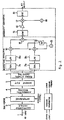
- FIGURES 2 and 3 respectively show block diagrams of a transmitter and a receiver both associated with the above-mentioned conventional transmission system.
- a 2-bits information data input into an input terminal 1 is transformed by a constellation mapper 2 into a four-phase QPSK constellation signal.
- the constellation in this context means a representation, in a complex vector plane, of the in-phase axis component and quadrature axis one in an quadrature modulation.
- the constellation In case of QPSK, the constellation has concentrically arranged four symbols with equidistant intervals therebetween, as shown in FIGURE 15. These constellation signals are collected as many as one frame as shown in FIGURE 1 to be written into an interleaver 3 comprised of memories.
- the symbol in the constellation signal in each OFDM carrier will be referred to as "modulation symbol of each carrier”
- the symbol in the OFDM signals i.e., the symbol in all the carriers will be referred to as "OFDM modulation symbol” or simply referred to as “symbol”. That is, one element in the two-dimensional plane, as shown in FIGURE 1, is the modulation symbol of each carrier, while the respective columns correspond to the OFDM modulation symbols.
- the coherent symbols (null and equalization reference symbols) are inserted into the interleaver 3 from where they are read out in conformity with a specific rule.
- the interleaved outputs are differentially encoded by a differential encoder 4.
- the differential encoding is a method for transmitting information by a phase difference between two consecutive symbols, thus characterized in that it needs no absolute reference signal. Provided this differential encoding should be performed for each carrier in the OFDM transmission. That is, processing is to be made in such a manner that the differential encoding is carried out for two consecutive symbols along the column direction, as shown in FIGURE 1. DAB has proposed mainly this sort of differential encoding. Then the differentially encoded output is transformed from a frequency domain into a time domain for every modulation symbol in an inverse FFT circuit 5. The respective columns, as shown in FIGURE 1, are output as time domain waveform for a certain period of time. Note that this output is in general a complex signal.
- the complex signal in this time domain is converted into an analog waveform by digital-analog converters 7a and 7b, followed by being frequency converted by the quadrature modulator after being band-limited at LPFs 8a and 8b.
- the quadrature modulator comprises mixers 10 and 11, a 90° phase shifter 12, a local oscillator 13 and a mixer 14. Taking the complex signals output from the inverse FFT circuit 5 as in-phase axis component I signal and quadrature axis component Q signal, this modulator synthetically modulates them by local oscillator output with zero phase and that with ninety degree phase.
- the output of the quadrature modulator being an intermediate frequency signal (referred to as IF signal), it is band limited by a BPF 15 such as a SAW filter, amplified at an amplifier 16 and then frequency converted in the section comprised of a mixer 17 and a local oscillator 18 to be output as a radio frequency signal (referred to as BF signal).
- IF signal intermediate frequency signal
- BPF 15 such as a SAW filter
- BF signal radio frequency signal
- FIGURE 3 a block diagram of the receiver associated with the above-mentioned transmission system will be explained hereinafter.
- the RF signal input into an input terminal 31 is band limited at a BPF 32. Desired signal is then selected at a channel tuner comprised of a mixer 34 and a variable local oscillator 35 through an amplifier 33 is band limited at the BPF 32. After further being band limited by a BPF 37 such as a SAW filter, the signal passes through a variable gain amplifier 38 and is detected at an quadrature detector comprised of mixers 39 and 40, a 90° phase shifter 41 and a variable local oscillator 53. This output is equivalent to the I and Q signals at the transmitter section. After being band limited at LPFs 42 and 43, these signals are digitized respectively at analog-digital converters 44 and 45 to be converted into complex digital signals.
- a BPF 37 such as a SAW filter
- the digital signals are distributed, and one of the distributed signals is fed to an envelope detector 46 to be used as a control signal for an automatic gain control (referred to as AGC) amplification.
- AGC automatic gain control
- Another distributed signal is fed to an FFT circuit 19 through guard symbol removers 49 and 50, and for each symbol of the signal in the time domain is transformed into the signal of frequency domain (symbol associated to each column in FIGURE 1.
- the complex digital symbol as distributed is fed to a sync, signal extractor 47 to detect the symbol and frame synchronization using the null symbol and other reference symbols.
- the detected output is input into a timing generator 48 to recover clock and timing signals required for respective signal processors.
- the signal processed by the FFT circuit is decomposed into modulation symbols for respective carriers, and then equalized for each carrier at an equalizer 55 and an equalization reference symbol detector 56.
- a differential detector 57 detects phase difference information (most of DAB proposed method not needing in general this equalization according to the QPSK differential detection, it is referred to here to clearly differentiate it from the present invention). As stated above, the information is transferred only by the constellation phase difference in the differentially encoded QPSK modulation, the phase difference is detected here. As a general rule the differential detector 57 is made of a simple differential detector.
- the differential detection output is restored into the initial frame construction by a deinterleaver 58 that carries out the processings inverse to the interleavings at the transmitter section. Furthermore the modulation symbols for respective carriers are demodulated into two-bit data at a constellation demapper 59 which invrsely performs the constellation conversion processed at the transmitter section.
- the digital TV broadcasting has also proposed a 16-quadrature amplitude modulation (referred to as 16QAM) and a 64-quadrature amplitude modulation (referred to as 64QAM) in addition to the QPSK.
- 16QAM 16-quadrature amplitude modulation
- 64QAM 64-quadrature amplitude modulation
- the modulation form that can be used in the OFDM transmission is (multi-valued) quadrature modulation and one similar thereto, namely a QPSK (equivalent to 4QAM), an N-QAM or an N-phase PSK (N: integer 2 or higher).
- a QPSK equivalent to 4QAM
- N N: integer 2 or higher
- the PSK larger than the 16-phase level is not generally used due to its required C/N ratio that is higher than the 16QAM.
- the QAMs other than 2QAM and 4QAM (2QAM and 4QAM are equivalent to the 2-phase PSK and the QPSK) is restrained in that it is difficult to differentially encode due to the characteristic of its constellation and that it should be demodulated through the coherent detection.
- the DAB transmission system known as a prior art performs a modulation presupposing such differential encoding as the QPSK.
- the digital TV broadcasting falls short of the transmission capacity in its modulation form with lower multi-valued level such as the QPSK that enables the differential encoding. In consequence therefore it is compelled to utilize such higher multi-valued modulation as is difficult to differentially encode.
- an object of the present invention to provide a transmission system, a transmitter and a receiver therefor as can realize a stable demodulation in the hierarchical OFDM transmission even under poor receiving conditions.
- Another object of the present invention is to provide such a transmission system, a transmitter and a receiver therefor as can demodulate stably the information at least from lower hierarchical layers.
- a hierarchical information transmission system includes, means for constructing a frame comprised of a plurality of symbols in an quadrature frequency multiplex signal transmission system that transmits a plurality of hierarchical information data using a modulation form with respectively different C/N ratios as required, means for performing the interleavings in both of the time and frequency domains, between the data using respective modulation forms within the frame, and means for making the respective modulatlon forms to associate with respective predetermined carriers.
- the transmission system includes means for constituting a frame comprised of a plurality of symbols, means for performing interleavings in both of the time and frequency domains among the data using respective modulation forms within the frame, means for differentially encoding at least a part of the modulation forms, and means for making respective modulation forms to associate with respectively predetermined carriers.
- a transmitter includes means for forming modulated signals, mens for making the plurality of hierarchical information data to associate with modulation forms of respectively different C/N ratios as required, means for performing the interleavings in both of the time and frequency domains among the modulatlon signals in different modulation forms within a frame comprised of a plurality of symbols, and means carrying out an inverse Fourier transform every symbol by making respective modulation forms to associate with respective predetermined carriers.
- a transmitter includes means for interleaving both in the time and frequency domains among the symbols in respective modulation forms within a frame comprised of a plurality of symbols, means for differentially encoding at least a part of the modulation forms, and means carrying out an inverse Fourier transform for every symbol by making respective modulation forms to associate with respective predetermined carriers.
- a receiver includes means for carrying out a Fourier transform for every symbol, means for recovering carriers using the Fourier transform output of specific carriers allocated to the lowest hierarchy of a plurality of modulation forms, means for coherently detecting signals of all the modulation forms using the recovered carriers, means for reconstructing a frame comprised of a plurality of symbols, means for carrying out deinterleavings in both of the time and frequency domains among the signals in respective modulation forms within the frame, and means for recovering a plurality of hierarchical information data from the modulation forms with respectively different C/N ratios as required.
- a receiver includes means for carrying out a Fourier transform for every symbol, means for recovering carriers using the lowest hierarchy of a plurality of modulation forms allocated to a specific carrier, means for coherently detecting other modulation forms using the recovered carriers, means for demodulating the lowest hierarchy of modulation form by a differential detection, means for reconstructing a frame comprised of a plurality of symbols, means for performing deinterleavings in both of the time and frequency domains among the signals in respective modulation forms within the frame, and means for recovering the plurality of hierarchical information data from the modulation forms of respective different C/N ratios as required depending to transmission conditions.
- the frame comprised of a plurality of symbols is constructed wherein the interleavings are performed in both of the time and the frequency domains among the data using their respective modulation forms.
- the respective modulation forms are associated to the respective predetermined carriers.
- differential encoding of at least in a part of the modulation forms allows to demodulate with ease the corresponding (lower hierarchical) information data at the receiver section without employing any coherent detection processing. Therefore the operation can be performed in such a manner that at least a part of the information data is demodulated despite such extremely unfavorable receiving conditions as makes it difficult to recover the carrier required for the coherent detection.
- modulation signals are produced using the aforesaid means by making the plurality of hierarchical information data to be associated to the respective modulation forms with different C/N ratios as required, with interleavings performed in both of the time and frequency domains among the signals of respective modulation forms within the frame comprised of a plurality of symbols. Thereafter the inverse Fourier transform produces an actual transformed wave, and then the respective modulation forms are allocated to the respective predetermined carriers for every symbol.
- a carrier recovery is attained using the Fourier transform output of the specific carrier allocated to the lowest hierarchy of the modulation form among the plurality of modulation forms.
- Using this recovered carrier enables to coherently detect the signals under any of or all the modulation forms.
- Deinterleavings are performed in both of the time and frequency domains among the signals in respective modulation forms within the frame with the plurality of hierarchical information data recovered from the modulation forms with respectively different C/N ratios as required. Furthermore the operation is afforded so that the lowest hierarchical modulation form can be demodulated by the differential detection.
- FIGURES 4 through 16 some embodiments of the present invention will be explained hereinafter.
- FIGURE 4 represents an embodiment transmission system according to the present invention, where a transmission frame construction corresponds to that in the conventional one, as shown in FIGURE 1.
- the row direction represents the frequency axis direction (i.e., OFDM carrier number), while the column direction represents the time axis direction (i.e., OFDM modulation symbol number).
- the carriers with the numbers 1 through n1 and N-n2 through N, located on both ends of the channel, are used as guard bands, but not used for effective data.
- the carrier with the number n1+1 is allocated for the lowest hierarchical information data among the hierarchically constructed information data.
- This example also illustrates that the intermediate hierarchical information data and the highest hierarchical (uppermost hierarchical) information data have been assigned to n1+2 carrier and a n1+3 carrier, respectively. Similarly and repeatedly the carriers and hierarchical information are made to associate with each other in the sequential order of the lowermost hierarchy, the intermediate hierarchy, the uppermost hierarchy and so on.
- the embodiment shows a QPSK as the modulation form in the lowermost hierarchy, a 16QAM as that in the intermediate hierarchy, and lastly a 64QAM as that of the uppermost hierarchy.
- a first symbol is taken as a null symbol for use of synchronization as in the conventional cases, while a second symbol is taken as an equalization reference symbol.
- a third symbol and subsequent are information symbols.
- a multi-valued modulation form when conducting a demodulation on the receiver section presupposes a coherent detection.
- the higher the multi-valued level raised the more a carrier recovery required for coherent detection becomes complicated, and also the more it becomes difficult to process in particular under unfavorable receiving conditions (for example, a low C/N ratio condition, a heavy fading condition, etc.).
- the transmission frame construction and establishment of the relationships between the respective carriers and the layers in the hierarchical construction according to the present invention however make it possible to recover carriers by selecting a modulation form with a lower multi-valued level already known in the receiver. In consequence the coherent detection can be performed with ease even under poor receiving conditions.
- the embodiment of the hierarchical arrangement illustrates the allocation sequence to each carrier such as the lowermost, the intermediate and the uppermost hierarchical layers and so on, the present invention should not be limited to the embodiment.
- the embodiment of the hierarchical arrangement employs a QPSK, a 16QAM and a 64QAM as the modulation forms in the lowest, the intermediate and the highest hierarchical layers, respectively.
- This embodiment gives a case where required C/N ratios in respective modulation forms are stepped by about 7 dB. Too little difference between the required C/N in these modulation forms annihilates the merits of the hierarchical transmission, while too large a difference makes it impossible to demodulate higher hierarchical layers of information at numerous receiving locations.
- the difference of 7 dB between required C/N ratios, if simply converted into transmission distance equals about 2.2 times, which is a suitable value to make use of the characteristics of the hierarchical transmission.
- interleavings in the present transmission system will be described hereinafter.
- a specific modulation form has been allotted to each carrier, where the interleavings are performed in both of the time and frequency domains between respective modulation forms (i.e., the respective hierarchical information data).
- modulation forms i.e., the respective hierarchical information data.
- FIGURE 5 shows an exemplary hierarchical construction not yet processed any interleaving.
- any number of hierarchical layers be transmitted, corresponding number of Interleavings are carried out on the number of transmitting hierarchical layers.
- information data are respectively written into memories along the frequency direction (row direction) in a sequential order, thus one column of data is converted into an OFDM modulation symbol. If in this case the data suffers an interference on a transmission channel, a bulk of series data are damaged, which may reduce the error correction capability of the receiver section.
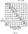
- FIGURE 6 depicts an example where interleavings have been executed on the symbols in the hierarchical construction.
- two consecutive data are isolated by a proper distance so as not to be adjacent with each other in the two-dimensional arrangement.
- the transmission error becomes similar to a random error rather than to a burst error, thereby enabling to prevent worsening the error correction capability.
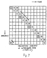
- FIGURE 7 gives another example for further optimization of the data restoration.
- two consecutive data are more isolated by much longer distance in the two-dimensional arrangement, by interleaving the data by every three units rather than every two units.
- the degree of the optimization may be defined in response to the size of the two-dimensional construction.
- This embodiment is characterized in that the modulation form in lower hierarchical layers makes use of the differential encoding method.
- the present invention allows for the differential encoding only for such lower hierarchical layers of modulation forms (for example, two-phase PSK, QPSK, 8-phase PSK, etc.) as can be differentially encoded in due consideration of the fact that the higher hierarchical layers of multi-valued modulation forms cannot be differentially encoded. That implies that specific carriers are modulated in the modulation form that includes differential encoding. This operation enables the signals in lower hierarchical layers to be demodulated by the differential detection on the receiver section.
- the coherent detection made possible by the signals in higher hierarchical layers contributes to ensure a higher transmission capacity in the multi-valued modulation form thus allowing for reception of higher quality of information.
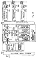
- FIGURE 8 illustrates a transmitter section of the embodiment according to the present invention.
- the transmission system for the transmitter is based on the above-described system according to the present invention.
- FIGURE 8 three hierarchical information data are assigned for three input terminals 501, 502 and 503. These three hierarchical information data are selectively coupled to their corresponding input terminals according to clocks for each hierarchical layer as output from a timing generator 538. This is because the three hierarchical information data have different transfer rates due to the different transmission capacities among the three hierarchical layers.
- the input information of respective hierarchical layers are each converted into a parallel data configuration in serial-parallel (S/P) converters 504, 505 and 506.
- S/P serial-parallel
- the layer employing the QPSK modulation is converted into a 2-bit parallel data
- the layers employing the 16QAM and 64QAM modulations are converted into a 4-bit and a 6-bit parallel data, respectively.
- the parallel data in respective hierarchical layers are transformed into symbols in the constellation of the respective modulation forms at constellation mappers 507, 508 and 509. This transformation is made by using read only memories (ROMs) etc.
- the outputs of the constellation mappers 507, 508 and 509 are a complex signal consisting of an in-phase axis component (I signal) and an quadrature axis component (Q signal).
- the timing generator 538 generates timing signals and clocks for use in the respective circuits as well as clocks for use in the respective layers, from clock signals and timing signals.
- the respective complex signals in the respective hierarchical layers are then applied into switches 510, 511 and 512 in the interleaver section.
- the switch 510 supplies its input to random access memories (RAMs) 513 and 514.
- the switch 511 supplies its input to RAMs 515 and 516, while the switch 512 supplies its input to RAMs 517 and 518.
- the outputs from the RAMs 513 and 514 are supplied to a switch 526, while the outputs from the RAMs 515 and 516 are supplied to a switch 527, and also the outputs from the RAMs 517 and 518 are supplied to a switch 528.
- the addresses of the respective memories are controlled by the addresses generated at a write address generator 529 and a read address generator 530.
- Two RAMs each are provided in the respective hierarchical layers in order that the write-in operation and the read-out operation may be alternately carried out, but consecutively between them.
- a differential detector 534 and a delay unit 535 are those intended for conducting the differential encoding which are shown here as an exemplary differential encoding limited to the lowermost hierarchical layers.
- the present invention includes also what does not contain the differential encoding process.
- the signals in the lower hierarchical layers can be demodulated by the differential detection at the receiver section. As this transmission does not need any carrier recovering operation, as described before, the probability of failing the reception of the transmitted signal becomes very low, even under unfavorable receiving conditions and makes it possible to have guaranteed minimum reception under poor receiving conditions.
- the multiplexed output is fed to the transmission signal processor.
- FIGURE 10 illustrates the detail of this transmission signal processor.
- the multiplexed output is converted at an inverse FFT circuit 541 to be output as a time domain waveform for every symbol. Then it is inserted a guard period symbol by a guard symbol inserter 542 to be output as an RF signal at a downstream quadrature modulator 24 and a frequency converter 25. Since this processing is the same as that in the conventional one, its detailed explanation will be omitted for simplicity of explanation.
- the interleaving is realized in the respective modulation forms corresponding to the respective hierarchical layers.
- the processing is so designed that the signals output from the interleaver are sequentially multiplexed with specific carriers modulated in specific modulation form at the inverse FFT output.
- FIGURE 9 shows another embodiment of transmitter according to the present invention.
- FIGURE 9 the transmission system used in the embodiment is the same as that of the embodiment described above.
- Like reference numerals denote like elements or portions in the drawings of the above embodiments.
- three hierarchical information data are input to the transmitter of FIGURE 9.
- the serial-parallel processing and constellation mapping are also the same as these in the above embodiment.
- the respective hierarchical layers are multiplexed at a multiplexer 601 together with the null symbol for synchronization and the reference symbol.
- An output from a switch 602 is input into RAMs 603 and 604.
- the outputs from the RAMs 603 and 604 are applied to a switch 607.
- the addresses of the RAMs 603 and 604 are given through switches 605 and 606, respectively.
- the interleaving is performed in conformity with the rule limited to within the respective hierarchical layers as above.
- their address spaces for each hierarchical layer are divided, then these divided regions are assigned by upper addresses.
- the addresses assigning the hierarchical layers are specified in hierarchical address generators 608 and 610 respectively in their write-in operation and the read-out operation.
- the lower addresses are common to the two processing systems that control them at address generators 609 and 611.
- a read/write (R/W) switching pulse generator 612 is also provided in the interleaver, for supplying read/write (R/W) switching pulses to the RAMs and the switches.
- the output of this interleaver is so instructed that the differential encoding carried out by the difference calculation is applied to the lower hierarchical layers and that whether this encoding should be carried out for each layer is controlled at a switch 615 and hierarchical timing generator 616. That is, the output of the switch 607 is not only directly supplied to the switch 615, but also indirectly supplied thereto through the differential encoding at a delay unit 613 and a differential detector 614. The switch 615 selects any one of the output to supply it to the transmission signal processor. The subsequent steps, which are exactly the same with the former embodiment, may be omitted.
- FIGURE 11 shows an embodiment of the receiver according to the present invention.
- FIGURE 11 the receiver is configured in conformity with the transmission system as discussed above according to the present invention.
- a received signal demodulator 801 the input RF signal is converted into the signal in the frequency domain by an FFT circuit 51 after processed the channel selection, the quadrature detection and the analog-digital conversion. Phases and amplitudes of the respective OFDM carriers (or I signal and Q signal) can thus be obtained.
- the complex signal output from the FFT circuit 51 are executed with an equalizing process and then separated for each hierarchical layer at a multiplexer 802.
- the respective layers which have been transferred beforehand with a carrier arrangement known in the receiver, can be easily separated.
- the timing generator 48 affords the clock for the uppermost hierarchical layer, that for intermediate layer and that for the lowermost layer.
- the complex signal as obtained from the demultiplexer 802 is time-adjusted at delay units 803 through 805 to be output in the original order of data from the deinterleaver by being oppositely processed entirely to the interleaving operation.
- the output of the uppermost hierarchical layer obtained from the demultiplexer 802 is input into a switch 811, while the output of the intermediate layer is input in a switch 812 through the delay unit 803.
- the output of the lowermost hierarchical layer is differentially operated at a differential detector 808 and a delay unit 807, the output of which is input into a switch 813.
- the construction of the deinterleaver being exactly the same with that in the transmitter section, is comprised of the switches 811 through 813, 821 through 829, RAMs 814 through 819, a write address generator 831 and a read address generator 832.
- the outputs of the switches 827, 828 and 829 are supplied to constellation demappers 841, 842 and 843, respectively. That is, the deinterleaved complex signals having I and Q components in respective hierarchical layers are converted into parallel data depending on the number of bits in the respective layers at the demappers 841 through 843. For instance, the QPSK signal is converted into the 2-bit parallel signal, while the 16QAM signal and the 64QAM signal are converted into the 4-bit and the 6-bit parallel signals, respectively. These parallel signals are then converted to their corresponding serial data at parallel-serial (P/S) converters 844 through 846.
- the clock suited to each hierarchical layer is provided from the timing generator 48 (see FIGURE 12).
- the differential detector comprised of the differential detector 806 and the delay unit 807 is illustrated as used only in the lowest hierarchical layer.
- the present invention is however not limited to the case, but covers another configuration in which the differential detection is bypassed. Further it is easy to selectively employs those configurations appropriately in response to the receiving conditions in this embodiment.
- the judgement of the receiving conditions is readily realized by observing, for instance, the dispersion of symbols in the constellation in the respective hierarchical layers.
- the carrier recovery is achieved by inputting only the modulation form in the lowest hierarchical layer into a carrier recovery circuit 52, as shown in FIGURE 12. This enables to perform the carrier recovery in the modulation form with the lowest multi-valued level which further makes the recovery easier.
- FIGURE 13 represents another embodiment of the receiver according to the present invention.
- FIGURE 13 the receiver is configured in conformity with the transmission system as discussed above according to the present invention.
- a received signal demodulator 901 the input RF signal is converted into the signal in the frequency domain by the FFT circuit 51 after processed the channel selection, the quadrature detection and the analog-digital conversion. Phases and amplitudes of the respective OFDM carriers (or I signal and Q signal) can thus be obtained.
- the complex signal output from the FFT circuit 51 are executed with an equalizing process and then supplied into a differential detector 911, a delay unit 912 and a switch 913.
- the differential detector 911, the delay unit 912 and the switch 918 execute the differential detection.
- the resulted output of the differential detection is then supplied into the switch 913.
- the switch 913 is controlled by a hierarchical timing generator 914 so that the differential detection output can be selectively derived when the signal in the lowest hierarchical layer is processed.
- the output from the switch 913 is then supplied into a switch 921 in the deinterleaver.
- the deinterleavr comprised of the switch 921 and switches 924 through 926, RAMs 922 and 923, hierarchical address generators 927 and 929, a write address generator 928, a read address generator 930, and a read/write switching pulse (R/W) generator 931, executes a deinterleaving operation which is opposite to the interleaving operation executed in the transmitter section.
- the above embodiment of the receiver is different from the former embodiment of the receiver, by that a demultiplexer 931 is located after the deinterleaver.
- a demultiplexer 931 is located after the deinterleaver.
- the signals in the respective hierarchical layers as obtained from the demultiplexer 931 are supplied to constellation demappers 941, 942 and 943 in the constellation demapper section. That is, the deinterleaved complex signals having I and Q components in respective hierarchical layers are converted into parallel data depending on the number of bits in the respective layers at the demappers 941 through 943.
- the QPSK signal is converted into the 2-bit parallel signal, while the 16QAM signal and the 64QAM signal are converted into the 4-bit and the 6-bit parallel signals, respectively. These parallel signals are then converted to their corresponding serial data at the parallel-serial (P/S) converters 844 through 846.
- the clock suited to each hierarchical layer is provided from the timing generator 48 (see FIGURE 14).
- the configuration as shown in FIGURE 14 is so designed that only the complex signal in modulation form in the lowest hierarchical layer as separated at a switch 950 is supplied to the carrier recovery circuit 52. This enables to perform the carrier recovery in the modulation form with the lowest multi-valued level which further makes the recovery easier.
- the present invention can provide an extremely preferable transmission system which is capable of serving for a stable demodulation as well as transmitters and receivers therefor in the OFDM hierarchical transmission system, even under poor receiving conditions.
- the present invention can also provide a transmission system which is capable of serving for a stable demodulation of at least lower layer of hierarchical information data by using a differential detection as well as transmitters and receivers therefor.
Landscapes
- Engineering & Computer Science (AREA)
- Computer Networks & Wireless Communication (AREA)
- Signal Processing (AREA)
- Digital Transmission Methods That Use Modulated Carrier Waves (AREA)
- Transmitters (AREA)
- Mobile Radio Communication Systems (AREA)
Abstract
Description
- The present invention relates to a digital transmission system capable of a hierarchical transmission in an quadrature frequency multiplex modulation, a modulating apparatus and a demodulating apparatus therefor.
- An quadrature frequency multiplex signal transmission system, which is generally called to as OFDM (Quadrature Frequency Division Multiplex) modulation or COFDM (Coded OFDM: "Coded" means channel coding for error correction) modulation, is one of digital modulation techniques which is planed to be adopted to digital audio broadcasting (referred to as DAB) by the ITU-R (ex-CCIR) in near future. The detail of this technique is described in the contribution document (TG11/3) issued from ITU-R and Report of the Television Society, Vol. 17, No.54, pp.7-12, BCS 93-33 (Sep. 1993). These prior arts will be discussed in the scope relevant to the present invention.
- Since one symbol of OFDM is composed of carriers of several hundreds through several thousands, it is possible to carry out interleavings in both of the time and frequency domains of the symbol. Because no continuous data lacks from data by previously applying interleavings even when a reception had failed for a length of time interval, the possibility of restoring data is heightened through an error correction processing at a receiver section. Similarly the possibility of restoring data through the error correction processing at the receiver section can be also enhanced, since, even if carriers over a certain range of frequency had been failed by selective fadings due to a multipath, etc., the interleaving can restore the continuous lack of data. The length of time interval of the frame is defined in depending on transmission conditions of the frame, so as that a required depth of interleaving should be obtained.
- There are some examples in the OFDM transmission system as proposed by the DAB, which employ such interleavings in both of the time and frequency domains in consideration of the poor receiving conditions in the mobile radio communication. This means that the frame consisting of several hundred symbols is altered the arrangement of the symbols in conformity with a prescribed rule.
- As shown in FIGURE 1 a frame comprised of 300 symbols and 148 carriers is constructed in time and frequency directions respectively. The first symbol is a null symbol (zero magnitude for all the carriers) to be used for synchronizing operations in the receiver section and the second symbol is an equalization reference symbol for removing multipath signals. Then comes a symbol comprised of fixed data for controlling signal transmission parameters, followed by information data (i.e., symbols of effective data). These interleavings are carried out using a RAM (Random Access Memory) associated to this frame provided at the transmitter section, where a writ-in operation is made in a prescribed sequential order, then a read-out operation in a sequence different from that for writing. The figure represents an instance where plural audio channels (33 channels) are transferred simultaneously with effective data period divided into equal 33 parts. It goes similarly with non-multiplex signal transmission.
- FIGURES 2 and 3 respectively show block diagrams of a transmitter and a receiver both associated with the above-mentioned conventional transmission system.
- In FIGURE 2, a 2-bits information data input into an
input terminal 1 is transformed by aconstellation mapper 2 into a four-phase QPSK constellation signal. The constellation in this context means a representation, in a complex vector plane, of the in-phase axis component and quadrature axis one in an quadrature modulation. In case of QPSK, the constellation has concentrically arranged four symbols with equidistant intervals therebetween, as shown in FIGURE 15. These constellation signals are collected as many as one frame as shown in FIGURE 1 to be written into aninterleaver 3 comprised of memories. For simplicity of explanations, the symbol in the constellation signal in each OFDM carrier will be referred to as "modulation symbol of each carrier" , while the symbol in the OFDM signals, i.e., the symbol in all the carriers will be referred to as "OFDM modulation symbol" or simply referred to as "symbol". That is, one element in the two-dimensional plane, as shown in FIGURE 1, is the modulation symbol of each carrier, while the respective columns correspond to the OFDM modulation symbols. The coherent symbols (null and equalization reference symbols) are inserted into theinterleaver 3 from where they are read out in conformity with a specific rule. The interleaved outputs are differentially encoded by adifferential encoder 4. The differential encoding is a method for transmitting information by a phase difference between two consecutive symbols, thus characterized in that it needs no absolute reference signal. Provided this differential encoding should be performed for each carrier in the OFDM transmission. That is, processing is to be made in such a manner that the differential encoding is carried out for two consecutive symbols along the column direction, as shown in FIGURE 1. DAB has proposed mainly this sort of differential encoding. Then the differentially encoded output is transformed from a frequency domain into a time domain for every modulation symbol in aninverse FFT circuit 5. The respective columns, as shown in FIGURE 1, are output as time domain waveform for a certain period of time. Note that this output is in general a complex signal. After a guard symbol period for preventing the inter-symbol interference by multipath (for detail refer to the bibliography) being inserted at aguard symbol inserter 6, the complex signal in this time domain is converted into an analog waveform by digital-analog converters LPFs 8a and 8b. The quadrature modulator comprisesmixers phase shifter 12, alocal oscillator 13 and amixer 14. Taking the complex signals output from theinverse FFT circuit 5 as in-phase axis component I signal and quadrature axis component Q signal, this modulator synthetically modulates them by local oscillator output with zero phase and that with ninety degree phase. The output of the quadrature modulator being an intermediate frequency signal (referred to as IF signal), it is band limited by aBPF 15 such as a SAW filter, amplified at anamplifier 16 and then frequency converted in the section comprised of amixer 17 and alocal oscillator 18 to be output as a radio frequency signal (referred to as BF signal). - Referring now to FIGURE 3 a block diagram of the receiver associated with the above-mentioned transmission system will be explained hereinafter.
- The RF signal input into an
input terminal 31 is band limited at aBPF 32. Desired signal is then selected at a channel tuner comprised of amixer 34 and a variablelocal oscillator 35 through anamplifier 33 is band limited at theBPF 32. After further being band limited by aBPF 37 such as a SAW filter, the signal passes through avariable gain amplifier 38 and is detected at an quadrature detector comprised ofmixers phase shifter 41 and a variablelocal oscillator 53. This output is equivalent to the I and Q signals at the transmitter section. After being band limited atLPFs digital converters envelope detector 46 to be used as a control signal for an automatic gain control (referred to as AGC) amplification. Another distributed signal is fed to anFFT circuit 19 throughguard symbol removers signal extractor 47 to detect the symbol and frame synchronization using the null symbol and other reference symbols. The detected output is input into atiming generator 48 to recover clock and timing signals required for respective signal processors. - After the guard period symbol is removed at guard symbol removers 129 and 130, the signal processed by the FFT circuit is decomposed into modulation symbols for respective carriers, and then equalized for each carrier at an
equalizer 55 and an equalizationreference symbol detector 56. Further, adifferential detector 57 detects phase difference information (most of DAB proposed method not needing in general this equalization according to the QPSK differential detection, it is referred to here to clearly differentiate it from the present invention). As stated above, the information is transferred only by the constellation phase difference in the differentially encoded QPSK modulation, the phase difference is detected here. As a general rule thedifferential detector 57 is made of a simple differential detector. Next, the differential detection output is restored into the initial frame construction by adeinterleaver 58 that carries out the processings inverse to the interleavings at the transmitter section. Furthermore the modulation symbols for respective carriers are demodulated into two-bit data at aconstellation demapper 59 which invrsely performs the constellation conversion processed at the transmitter section. - The recent general trend is toward the digital broadcasting not only the sound but also TV signal, which has led to some proposals for using the OFDM also in the digital TV broadcasting. On the other hand since the digital TV broadcasting requires a higher transmission capacity than the DAB, a modulation form is customarily used with higher transmission efficiency. What is problematic in this system is that the modulation with higher transmission efficiency requires in general better transmission conditions, namely better receiving C/N ratio (carrier to noise ratio). In the DAB, for example, a quadrature phase shift keying (referred to as QPSK) is used a modulation form to modulate the respective carriers of the OFDM. The digital TV broadcasting has also proposed a 16-quadrature amplitude modulation (referred to as 16QAM) and a 64-quadrature amplitude modulation (referred to as 64QAM) in addition to the QPSK. It should be noted here that in any multi-valued modulation form the more the multi-valued level number, the required C/N ratio increases more thereby reducing the service area. Moreover it is one of the characteristics of the digital broadcasting that even a trifling geographical difference may cause worse receiving conditions. In some cases the reception might be absolutely impossible. To overcome such a situation proposed has been a concept called "graceful degradation." This concept consists in a hierarchical demodulation of such information only as can be received in terms of the receiving conditions of the receiver.
- The modulation form that can be used in the OFDM transmission is (multi-valued) quadrature modulation and one similar thereto, namely a QPSK (equivalent to 4QAM), an N-QAM or an N-phase PSK (N:
integer 2 or higher). Provided the PSK larger than the 16-phase level is not generally used due to its required C/N ratio that is higher than the 16QAM. By the way the QAMs other than 2QAM and 4QAM (2QAM and 4QAM are equivalent to the 2-phase PSK and the QPSK) is restrained in that it is difficult to differentially encode due to the characteristic of its constellation and that it should be demodulated through the coherent detection. - As has so far been discussed, the DAB transmission system known as a prior art performs a modulation presupposing such differential encoding as the QPSK. In consideration of the digital TV broadcasting, however, it falls short of the transmission capacity in its modulation form with lower multi-valued level such as the QPSK that enables the differential encoding. In consequence therefore it is compelled to utilize such higher multi-valued modulation as is difficult to differentially encode.
- Even such a hierarchical transmission as the graceful degradation using a modulation form with higher multi-valued levels only or using simultaneously plural modulation forms with different C/N ratios required in such a multicarrier transmission as the OFDM signifies nothing unless a stable demodulatlon operation is systematically guaranteed under poor receiving conditions. The prior art made no contrivance to stabilize the receiving operation as a transmission system except the utilization of the null symbols.
- It is, therefore, an object of the present invention to provide a transmission system, a transmitter and a receiver therefor as can realize a stable demodulation in the hierarchical OFDM transmission even under poor receiving conditions.
- Another object of the present invention is to provide such a transmission system, a transmitter and a receiver therefor as can demodulate stably the information at least from lower hierarchical layers.
- In order to achieve the above object, a hierarchical information transmission system according to one aspect of the present invention includes, means for constructing a frame comprised of a plurality of symbols in an quadrature frequency multiplex signal transmission system that transmits a plurality of hierarchical information data using a modulation form with respectively different C/N ratios as required, means for performing the interleavings in both of the time and frequency domains, between the data using respective modulation forms within the frame, and means for making the respective modulatlon forms to associate with respective predetermined carriers.
- Furthermore the transmission system according to another aspect of the present invention includes means for constituting a frame comprised of a plurality of symbols, means for performing interleavings in both of the time and frequency domains among the data using respective modulation forms within the frame, means for differentially encoding at least a part of the modulation forms, and means for making respective modulation forms to associate with respectively predetermined carriers.
- According to another aspect of the present invention a transmitter includes means for forming modulated signals, mens for making the plurality of hierarchical information data to associate with modulation forms of respectively different C/N ratios as required, means for performing the interleavings in both of the time and frequency domains among the modulatlon signals in different modulation forms within a frame comprised of a plurality of symbols, and means carrying out an inverse Fourier transform every symbol by making respective modulation forms to associate with respective predetermined carriers.
- Furthermore a transmitter according to another aspect of the present invention includes means for interleaving both in the time and frequency domains among the symbols in respective modulation forms within a frame comprised of a plurality of symbols, means for differentially encoding at least a part of the modulation forms, and means carrying out an inverse Fourier transform for every symbol by making respective modulation forms to associate with respective predetermined carriers.
- According to another aspect of the present invention a receiver includes means for carrying out a Fourier transform for every symbol, means for recovering carriers using the Fourier transform output of specific carriers allocated to the lowest hierarchy of a plurality of modulation forms, means for coherently detecting signals of all the modulation forms using the recovered carriers, means for reconstructing a frame comprised of a plurality of symbols, means for carrying out deinterleavings in both of the time and frequency domains among the signals in respective modulation forms within the frame, and means for recovering a plurality of hierarchical information data from the modulation forms with respectively different C/N ratios as required.
- Furthermore a receiver according to another aspect of the present invention includes means for carrying out a Fourier transform for every symbol, means for recovering carriers using the lowest hierarchy of a plurality of modulation forms allocated to a specific carrier, means for coherently detecting other modulation forms using the recovered carriers, means for demodulating the lowest hierarchy of modulation form by a differential detection, means for reconstructing a frame comprised of a plurality of symbols, means for performing deinterleavings in both of the time and frequency domains among the signals in respective modulation forms within the frame, and means for recovering the plurality of hierarchical information data from the modulation forms of respective different C/N ratios as required depending to transmission conditions.
- In the quadrature frequency multiplex signal transmission system, by using the foregoing means, the plurality of hierarchical information data using the modulation forms with respectively different C/N ratios as required, the frame comprised of a plurality of symbols is constructed wherein the interleavings are performed in both of the time and the frequency domains among the data using their respective modulation forms. The respective modulation forms are associated to the respective predetermined carriers. Thus in the receiver section carriers for use in the coherent detection can be recovered only by the lower hierarchical modulation forms, thereby extremely stabilizing the operation of the receiver even under poor receiving conditions.
- Further the differential encoding of at least in a part of the modulation forms allows to demodulate with ease the corresponding (lower hierarchical) information data at the receiver section without employing any coherent detection processing. Therefore the operation can be performed in such a manner that at least a part of the information data is demodulated despite such extremely unfavorable receiving conditions as makes it difficult to recover the carrier required for the coherent detection.
- According to the transmitter having the abovementioned means, modulation signals are produced using the aforesaid means by making the plurality of hierarchical information data to be associated to the respective modulation forms with different C/N ratios as required, with interleavings performed in both of the time and frequency domains among the signals of respective modulation forms within the frame comprised of a plurality of symbols. Thereafter the inverse Fourier transform produces an actual transformed wave, and then the respective modulation forms are allocated to the respective predetermined carriers for every symbol.
- Further the operation is afforded so that at least a part of the modulation forms can be differentially encoded.
- According to the receiver, after the Fourier transform has been performed on every symbol by the foregoing means, a carrier recovery is attained using the Fourier transform output of the specific carrier allocated to the lowest hierarchy of the modulation form among the plurality of modulation forms. Using this recovered carrier enables to coherently detect the signals under any of or all the modulation forms. Deinterleavings are performed in both of the time and frequency domains among the signals in respective modulation forms within the frame with the plurality of hierarchical information data recovered from the modulation forms with respectively different C/N ratios as required. Furthermore the operation is afforded so that the lowest hierarchical modulation form can be demodulated by the differential detection.
- Additional objects and advantages of the present invention will be apparent to persons skilled in the art from a study of the following description and the accompanying drawings, which are hereby incorporated in and constitute a part of this specification.
- For a better understandings of the present invention and many of the attendant advantages thereof, reference will now be made by way of example to the accompanying drawings, wherein:
- FIGURE 1 is a diagram for explaining a conventional hierarchical OFDM transmission frame;
- FIGURE 2 is a block diagram showing a conventional OFDM transmitter;
- FIGURE 3 a block diagram showing a conventional OFDM receiver;
- FIGURE 4 is a diagram for explaining the hierarchical OFDM transmission frame in an embodiment according to the present invention;
- FIGURE 5 is an exemplary hierarchical construction prior to an interleavins, according to the present invention;
-
FIGURS 6 is an exemplary hierarchical construction after an interleaving, according to the present invention; - FIGURE 7 is another exemplary hierarchical construction after an interleaving, according to the present invention;
- FIGURE 8 is a block diagram showing an embodiment of the OFDM transmitter according to the present invention;
- FIGURE 9 represents a block diagram showing another embodiment of the OFDM transmitter according to the present invention;
- FIGURE 10 is a block diagram for illustrating the details of the transmission signal processors of FIGURES 8 and 9;
- FIGURE 11 is a block diagram showing an embodiment of the OFDM receiver according to the present invention;
- FIGURE 12 is a block diagram for illustrating the details of the receiving demodulation section of FIGURE 11;
- FIGURE 13 is a block diagram showing another embodiment of the OFDM receiver according to the present invention;
- FIGURE 14 is a block diagram for illustrating the details of the receiving demodulation section of FIGURE 13;
- FIGURE 15 is an explanatory drawing illustrating the QPSK constellation; and
- FIGURE 16 illustrates examples of the constellation under other modulation forms;
- Referring now to the drawings FIGURES 4 through 16, some embodiments of the present invention will be explained hereinafter.
- FIGURE 4 represents an embodiment transmission system according to the present invention, where a transmission frame construction corresponds to that in the conventional one, as shown in FIGURE 1.
- In a two-dimensional arrangement, as shown in FIGURE 4. the row direction represents the frequency axis direction (i.e., OFDM carrier number), while the column direction represents the time axis direction (i.e., OFDM modulation symbol number). What follows elicit the differences from the conventional system.
- The carriers with the
numbers 1 through n1 and N-n2 through N, located on both ends of the channel, are used as guard bands, but not used for effective data. The carrier with the number n1+1 is allocated for the lowest hierarchical information data among the hierarchically constructed information data. This example also illustrates that the intermediate hierarchical information data and the highest hierarchical (uppermost hierarchical) information data have been assigned to n1+2 carrier and a n1+3 carrier, respectively. Similarly and repeatedly the carriers and hierarchical information are made to associate with each other in the sequential order of the lowermost hierarchy, the intermediate hierarchy, the uppermost hierarchy and so on. - The embodiment, as shown in FIGURE 4, shows a QPSK as the modulation form in the lowermost hierarchy, a 16QAM as that in the intermediate hierarchy, and lastly a 64QAM as that of the uppermost hierarchy. In the time axis direction a first symbol is taken as a null symbol for use of synchronization as in the conventional cases, while a second symbol is taken as an equalization reference symbol. A third symbol and subsequent are information symbols.
- Establishing associations between the respective carriers and the hierarchical layers with such a frame construction allows a receiver section to know beforehand which carrier has been modulated in which modulation form, which not merely facilitates the extraction of information of respective hierarchical layers but gives the following effects.
- A multi-valued modulation form, if used, when conducting a demodulation on the receiver section presupposes a coherent detection. Here, it is known that the higher the multi-valued level raised, the more a carrier recovery required for coherent detection becomes complicated, and also the more it becomes difficult to process in particular under unfavorable receiving conditions (for example, a low C/N ratio condition, a heavy fading condition, etc.). The transmission frame construction and establishment of the relationships between the respective carriers and the layers in the hierarchical construction according to the present invention however make it possible to recover carriers by selecting a modulation form with a lower multi-valued level already known in the receiver. In consequence the coherent detection can be performed with ease even under poor receiving conditions.
- Although the embodiment of the hierarchical arrangement, as shown in FIGURE 4, illustrates the allocation sequence to each carrier such as the lowermost, the intermediate and the uppermost hierarchical layers and so on, the present invention should not be limited to the embodiment.
- The embodiment of the hierarchical arrangement, as shown in FIGURE 4, employs a QPSK, a 16QAM and a 64QAM as the modulation forms in the lowest, the intermediate and the highest hierarchical layers, respectively. This embodiment gives a case where required C/N ratios in respective modulation forms are stepped by about 7 dB. Too little difference between the required C/N in these modulation forms annihilates the merits of the hierarchical transmission, while too large a difference makes it impossible to demodulate higher hierarchical layers of information at numerous receiving locations. The difference of 7 dB between required C/N ratios, if simply converted into transmission distance equals about 2.2 times, which is a suitable value to make use of the characteristics of the hierarchical transmission. At the same time these modulation forms, if combined, give about 24 Mbps as an overall transmission bit rate in a 6 MHz channel. Even in consideration of the guard band and the like factors, 20 Mbps can be ensured to transmit the required transmission capacity (approximately 18 Mbps) of the candidates in the U.S. ATV system. The value of the bit rate is therefore of the appropriate level from this viewpoint. It should be noted however that this combination does not limit the scope of the present invention.
- Now a more concrete example of the interleavings in the present transmission system will be described hereinafter. Basically a specific modulation form has been allotted to each carrier, where the interleavings are performed in both of the time and frequency domains between respective modulation forms (i.e., the respective hierarchical information data). These interleavings heighten the endurance against variations in a frequency selective fading and a temporal transmission characteristic.
- FIGURE 5 shows an exemplary hierarchical construction not yet processed any interleaving. When any number of hierarchical layers be transmitted, corresponding number of Interleavings are carried out on the number of transmitting hierarchical layers. In FIGURE 5, information data are respectively written into memories along the frequency direction (row direction) in a sequential order, thus one column of data is converted into an OFDM modulation symbol. If in this case the data suffers an interference on a transmission channel, a bulk of series data are damaged, which may reduce the error correction capability of the receiver section.
- FIGURE 6 depicts an example where interleavings have been executed on the symbols in the hierarchical construction. In this case, two consecutive data are isolated by a proper distance so as not to be adjacent with each other in the two-dimensional arrangement. Even when the interference as above arises, the transmission error becomes similar to a random error rather than to a burst error, thereby enabling to prevent worsening the error correction capability.
- FIGURE 7 gives another example for further optimization of the data restoration. In this case, two consecutive data are more isolated by much longer distance in the two-dimensional arrangement, by interleaving the data by every three units rather than every two units. The degree of the optimization may be defined in response to the size of the two-dimensional construction.
- Although the following have been already described before, these interleaving processes are repeatedly conducted only on the same modulation forms, as shown in FIGURE 4. This fact, which characterizes the present invention, is a factor required to guarantee the effects.
- Now another embodiment of the transmission system according to the present invention will be explained hereinafter. The details of the embodiment will be also explained in later sections as paragraphed by "transmitter" and "receiver". Hereinafter the principle and the effects of this transmission system will be discussed in first.
- This embodiment is characterized in that the modulation form in lower hierarchical layers makes use of the differential encoding method. Although in the conventional systems requires the differential encoding in the modulation forms for all the carriers, the present invention allows for the differential encoding only for such lower hierarchical layers of modulation forms (for example, two-phase PSK, QPSK, 8-phase PSK, etc.) as can be differentially encoded in due consideration of the fact that the higher hierarchical layers of multi-valued modulation forms cannot be differentially encoded. That implies that specific carriers are modulated in the modulation form that includes differential encoding. This operation enables the signals in lower hierarchical layers to be demodulated by the differential detection on the receiver section. Because the differential detection needs not any carrier recovering operation, it is less apprehended that the reception becomes impossible due to poor transmission conditions. Consequently a guaranteed minimum reception is given even under any unfavorable receiving conditions. The coherent detection made possible by the signals in higher hierarchical layers contributes to ensure a higher transmission capacity in the multi-valued modulation form thus allowing for reception of higher quality of information.
- FIGURE 8 illustrates a transmitter section of the embodiment according to the present invention.
- The transmission system for the transmitter is based on the above-described system according to the present invention.
- In FIGURE 8 three hierarchical information data are assigned for three
input terminals timing generator 538. This is because the three hierarchical information data have different transfer rates due to the different transmission capacities among the three hierarchical layers. - The input information of respective hierarchical layers are each converted into a parallel data configuration in serial-parallel (S/P)
converters - The above description may be understood by referring to constellations of respective modulation forms, like those as shown in FIGURES 14 and 15. Further if an 8-phase PSK and a 32QAM are to be employed, there are needed techniques of 3-bit and 5-bit parallel conversions.
- The parallel data in respective hierarchical layers are transformed into symbols in the constellation of the respective modulation forms at
constellation mappers constellation mappers timing generator 538 generates timing signals and clocks for use in the respective circuits as well as clocks for use in the respective layers, from clock signals and timing signals. - The respective complex signals in the respective hierarchical layers are then applied into
switches - The
switch 510 supplies its input to random access memories (RAMs) 513 and 514. Theswitch 511 supplies its input toRAMs RAMs RAMs switch 526, while the outputs from theRAMs switch 527, and also the outputs from theRAMs switch 528. The addresses of the respective memories are controlled by the addresses generated at awrite address generator 529 and aread address generator 530. Two RAMs each are provided in the respective hierarchical layers in order that the write-in operation and the read-out operation may be alternately carried out, but consecutively between them. - Then the complex signals interleaved in these hierarchical layers are time-adjusted in delay units (Ds) 531, 532 and 533 in the multiplexer section, and then multiplexed sequentially at a
multiplexer 536 together with the null symbols and the reference symbols for synchronization. Adifferential detector 534 and adelay unit 535 are those intended for conducting the differential encoding which are shown here as an exemplary differential encoding limited to the lowermost hierarchical layers. As described above the present invention includes also what does not contain the differential encoding process. When transmitted with differential encoding, the signals in the lower hierarchical layers can be demodulated by the differential detection at the receiver section. As this transmission does not need any carrier recovering operation, as described before, the probability of failing the reception of the transmitted signal becomes very low, even under unfavorable receiving conditions and makes it possible to have guaranteed minimum reception under poor receiving conditions. - The multiplexed output is fed to the transmission signal processor. FIGURE 10 illustrates the detail of this transmission signal processor. The multiplexed output is converted at an
inverse FFT circuit 541 to be output as a time domain waveform for every symbol. Then it is inserted a guard period symbol by aguard symbol inserter 542 to be output as an RF signal at adownstream quadrature modulator 24 and afrequency converter 25. Since this processing is the same as that in the conventional one, its detailed explanation will be omitted for simplicity of explanation. - Thus, the interleaving is realized in the respective modulation forms corresponding to the respective hierarchical layers. The processing is so designed that the signals output from the interleaver are sequentially multiplexed with specific carriers modulated in specific modulation form at the inverse FFT output.
- FIGURE 9 shows another embodiment of transmitter according to the present invention.
- In FIGURE 9 the transmission system used in the embodiment is the same as that of the embodiment described above. Like reference numerals denote like elements or portions in the drawings of the above embodiments. Similarly three hierarchical information data are input to the transmitter of FIGURE 9. The serial-parallel processing and constellation mapping are also the same as these in the above embodiment.
- Then the respective hierarchical layers are multiplexed at a
multiplexer 601 together with the null symbol for synchronization and the reference symbol. An output from a switch 602 is input intoRAMs RAMs switch 607. The addresses of theRAMs switches hierarchical address generators address generators pulse generator 612 is also provided in the interleaver, for supplying read/write (R/W) switching pulses to the RAMs and the switches. - In similar to the former embodiment, the output of this interleaver is so instructed that the differential encoding carried out by the difference calculation is applied to the lower hierarchical layers and that whether this encoding should be carried out for each layer is controlled at a
switch 615 andhierarchical timing generator 616. That is, the output of theswitch 607 is not only directly supplied to theswitch 615, but also indirectly supplied thereto through the differential encoding at a delay unit 613 and adifferential detector 614. Theswitch 615 selects any one of the output to supply it to the transmission signal processor. The subsequent steps, which are exactly the same with the former embodiment, may be omitted. - FIGURE 11 shows an embodiment of the receiver according to the present invention.
- In FIGURE 11 the receiver is configured in conformity with the transmission system as discussed above according to the present invention. In this description any explanation of portions the same in the above embodiments will be omitted. As is clear from a comparison of FIGURE 12 with FIGURE 13, in a received
signal demodulator 801 the input RF signal is converted into the signal in the frequency domain by anFFT circuit 51 after processed the channel selection, the quadrature detection and the analog-digital conversion. Phases and amplitudes of the respective OFDM carriers (or I signal and Q signal) can thus be obtained. The complex signal output from theFFT circuit 51 are executed with an equalizing process and then separated for each hierarchical layer at amultiplexer 802. The respective layers, which have been transferred beforehand with a carrier arrangement known in the receiver, can be easily separated. In the circuit, as shown in FIGURE 12, thetiming generator 48 affords the clock for the uppermost hierarchical layer, that for intermediate layer and that for the lowermost layer. - Next, the complex signal as obtained from the
demultiplexer 802 is time-adjusted atdelay units 803 through 805 to be output in the original order of data from the deinterleaver by being oppositely processed entirely to the interleaving operation. The output of the uppermost hierarchical layer obtained from thedemultiplexer 802 is input into a switch 811, while the output of the intermediate layer is input in a switch 812 through thedelay unit 803. The output of the lowermost hierarchical layer is differentially operated at a differential detector 808 and adelay unit 807, the output of which is input into aswitch 813. The construction of the deinterleaver, being exactly the same with that in the transmitter section, is comprised of the switches 811 through 813, 821 through 829,RAMs 814 through 819, awrite address generator 831 and aread address generator 832. - The outputs of the
switches constellation demappers demappers 841 through 843. For instance, the QPSK signal is converted into the 2-bit parallel signal, while the 16QAM signal and the 64QAM signal are converted into the 4-bit and the 6-bit parallel signals, respectively. These parallel signals are then converted to their corresponding serial data at parallel-serial (P/S)converters 844 through 846. The clock suited to each hierarchical layer is provided from the timing generator 48 (see FIGURE 12). - The differential detector comprised of the
differential detector 806 and thedelay unit 807 is illustrated as used only in the lowest hierarchical layer. The present invention is however not limited to the case, but covers another configuration in which the differential detection is bypassed. Further it is easy to selectively employs those configurations appropriately in response to the receiving conditions in this embodiment. The judgement of the receiving conditions is readily realized by observing, for instance, the dispersion of symbols in the constellation in the respective hierarchical layers. - Next, the carrier recovery is achieved by inputting only the modulation form in the lowest hierarchical layer into a
carrier recovery circuit 52, as shown in FIGURE 12. This enables to perform the carrier recovery in the modulation form with the lowest multi-valued level which further makes the recovery easier. - FIGURE 13 represents another embodiment of the receiver according to the present invention.
- In FIGURE 13 the receiver is configured in conformity with the transmission system as discussed above according to the present invention. In this description any explanation of portions the same in the above embodiments will be omitted. As is clear from a comparison of FIGURE 14 with FIGURE 3, in a received
signal demodulator 901 the input RF signal is converted into the signal in the frequency domain by theFFT circuit 51 after processed the channel selection, the quadrature detection and the analog-digital conversion. Phases and amplitudes of the respective OFDM carriers (or I signal and Q signal) can thus be obtained. The complex signal output from theFFT circuit 51 are executed with an equalizing process and then supplied into adifferential detector 911, adelay unit 912 and aswitch 913. Thedifferential detector 911, thedelay unit 912 and the switch 918 execute the differential detection. The resulted output of the differential detection is then supplied into theswitch 913. Theswitch 913 is controlled by ahierarchical timing generator 914 so that the differential detection output can be selectively derived when the signal in the lowest hierarchical layer is processed. The output from theswitch 913 is then supplied into aswitch 921 in the deinterleaver. The deinterleavr, comprised of theswitch 921 andswitches 924 through 926,RAMs hierarchical address generators write address generator 928, aread address generator 930, and a read/write switching pulse (R/W)generator 931, executes a deinterleaving operation which is opposite to the interleaving operation executed in the transmitter section. - The above embodiment of the receiver is different from the former embodiment of the receiver, by that a
demultiplexer 931 is located after the deinterleaver. As operations in this embodiment are carried out in an entirely opposite way to that in the second embodiment of the transmitter section, its detailed explanations will be omitted for simplicity of explanation. The signals in the respective hierarchical layers as obtained from thedemultiplexer 931 are supplied toconstellation demappers demappers 941 through 943. For instance, the QPSK signal is converted into the 2-bit parallel signal, while the 16QAM signal and the 64QAM signal are converted into the 4-bit and the 6-bit parallel signals, respectively. These parallel signals are then converted to their corresponding serial data at the parallel-serial (P/S)converters 844 through 846. The clock suited to each hierarchical layer is provided from the timing generator 48 (see FIGURE 14). - The configuration as shown in FIGURE 14 is so designed that only the complex signal in modulation form in the lowest hierarchical layer as separated at a
switch 950 is supplied to thecarrier recovery circuit 52. This enables to perform the carrier recovery in the modulation form with the lowest multi-valued level which further makes the recovery easier. - As described above, the present invention can provide an extremely preferable transmission system which is capable of serving for a stable demodulation as well as transmitters and receivers therefor in the OFDM hierarchical transmission system, even under poor receiving conditions. The present invention can also provide a transmission system which is capable of serving for a stable demodulation of at least lower layer of hierarchical information data by using a differential detection as well as transmitters and receivers therefor.
- While there have been illustrated and described what are at present considered to be preferred embodiments of the present invention, it will be understood by those skilled in the art that various changes and modifications may be made, and equivalents may be substituted for elements thereof without departing from the true scope of the present invention. In addition, many modifications may be made to adapt a particular situation or material to the teaching of the present invention without departing from the central scope thereof. Therefor, it is intended that the present invention not be limited to the particular embodiment disclosed as the best mode contemplated for carrying out the present invention, but that the present invention includes all embodiments falling within the scope of the appended claims.
- The foregoing description and the drawings are regarded by the applicant as including a variety of individually inventive concepts, some of which may lie partially or wholly outside the scope of some or all of the following claims. The fact that the applicant has chosen at the time of filing of the present application to restrict the claimed scope of protection in accordance with the following claims is not to be taken as a disclaimer or alternative inventive concepts that are included in the contents of the application and could be defined by claims differing in scope from the following claims, which different claims may be adopted subsequently during prosecution, for example, for the purposes of a divisional application.
Claims (12)
- A hierarchical quadrature frequency multiplex signal transmission system for transmitting multiple layers of hierarchical information data modulated using a plurality of hierarchically graded modulation systems with required C/N ratios different from each other, characterized in that the multiple layers of the hierarchical information data are constituted into a frame comprising a plurality of symbols of the information data, the symbols in a prescribed layer of the hierarchical information data having a particular grade modulation form are interleaved in both directions of the time axis and the frequency axis, and the plurality of hierarchically graded modulation forms are respectively associated with individually predetermined carriers.
- A hierarchical quadrature frequency multiplex signal transmission system for transmitting multiple layers of hierarchical information data modulated using a plurality of hierarchically graded modulation forms with required C/N ratios different from each other, characterized in that the multiple layers of the hierarchical information data are constituted into a frame comprising a plurality of symbols of the information data, the symbols in a prescribed layer of the hierarchical information data having a particular grade modulation form are interleaved in both directions of the time axis and the frequency axis, and the plurality of hierarchically graded modulation forms are respectively associated with individually predetermined carriers, and wherein at least one of the modulation forms is differentially encoded.
- A hierarchical quadrature frequency multiplex signal transmission system as claimed in claim 1, characterized in that the plurality of hierarchically graded modulation forms include a QPSK modulation, a 16QAM modulation and a 64QAM modulation.
- A hierarchical quadrature frequency multiplex signal transmission system as claimed in claim 2, characterized in that the plurality of hierarchically graded modulation forms include a QPSK modulation, a 16QAM modulation and a 64QAM modulation, and wherein the QPSK modulation is differentially encoded.
- A hierarchical quadrature frequency multiplex signal transmission apparatus comprising:
means for producing a plurality of modulated signals in which multiple layers of hierarchical information data are associated with a plurality of hierarchically graded modulation forms respectively conveying required C/N ratios:
means, in a frame constituted by symbols of the multiple layers of the hierarchical information data, for interleaving the symbols in a prescribed layer of the hierarchical information data associated with a particular grade modulation form in both directions of the time axis and the frequency axis; and
means for performing an inverse Fourier transform on every symbol, by allocating a plurality of hierarchically graded modulation forms to respective predetermined carriers. - A hierarchical quadrature frequency multiplex signal transmission apparatus comprising:
means for producing a plurality of modulated signals in which multiple layers of hierarchical information data are associated with a plurality of hierarchically graded modulation forms respectively conveying required C/N ratios:
means, in a frame constituted by symbols of the multiple layers of the hierarchical information data, for Interleaving the symbols in a prescribed layer of the hierarchical information data associated with a particular grade modulation form in both directions of the time axis and the frequency axis; and
means for performing an inverse Fourier transform on every symbol, by allocating a plurality of hierarchically graded modulation forms to respective predetermined carriers,
and wherein at least one of the of the hierarchically graded modulation forms is differentially encoded. - An quadrature frequency multiplex signal transmission apparatus as claimed in claim 6, characterized in that the differential encoding is associated to the lowest grade hierarchical modulation form.
- A hierarchical quadrature frequency multiplex signal receiving apparatus, comprising:
means for receiving to demodulate signals transmitted by means of hierarchical quadrature frequency multiplex signal transmission system for transmitting multiple layers of hierarchical information data modulated using a plurality of hierarchically graded modulation forms with required C/N ratios different from each other, characterized in that the multiple layers of the hierarchical information data are constituted into a frame comprising a plurality of symbols of the information data, the symbols in a respective layer of the hierarchical information data having a particular grade modulation form are interleaved in both directions of the time axis and the frequency axis, and the plurality of hierarchically graded modulation forms are respectively associated with individually predetermined carriers;
means for performing a Fourier transform for every symbols of the demodulated output;
means for recovering carriers using the Fourier transform output of a particular carrier allocated to the lowest hierarchical modulation form among the plural modulation forms;
means for coherently detecting signals associated with all of the hierarchically graded modulation forms using the recovered carriers;
means for reconstructing the detected signals into a frame composed of a plurality of symbols;
means for deinterleaving frame symbols in a prescribed layer of the hierarchical information data having a particular grade modulation form in both directions of the time axis and the frequency axis; and
means for recovering a plurality of hierarchical information data from the respective differing modulation forms with required C/N ratios different from each other. - A hierarchical quadrature frequency multiplex signal receiving apparatus, comprising:
means for receiving to demodulate signals transmitted by means of hierarchical quadrature frequency multiplex signal transmission system for transmitting multiple layers of hierarchical information data modulated using a plurality of hierarchically graded modulation forms with required C/N ratios different from each other, characterized in that the multiple layers of the hierarchical information data are constituted into a frame comprising a plurality of symbols of the information data, the symbols in a respective layer of the hierarchical information data having a particular grade modulation form are interleaved in both directions of the time axis and the frequency axis, and the plurality of hierarchically graded modulation forms are respectively associated with individually predetermined carriers;
means for performing a Fourier transform for every symbols of the demodulated output;
means for recovering carriers using the Fourier transform output of a particular carrier allocated to the lowest hierarchical modulation form among the plural modulation forms;
means for reconstructing the detected signals into a frame composed of a plurality of symbols;
means for coherently detecting signals associated with the hierarchically graded modulation forms other than the lowest grade modulation form using the recovered carriers;
means for demodulating signals associated with the lowest grade modulation form by means of a differential detection;
means for deinterleaving frame symbols in a prescribed layer of the hierarchical information data having a particular grade modulation form in both directions of the time axis and the frequency axis; and
means for recovering a plurality of hierarchical information data from the respective differing modulation forms with required C/N ratios different from each other. - A hierarchical quadrature frequency multiplex signal transmission system, characterized in that in a frame plotted its time axis and frequency axis with symbols and carriers, respectively, a set of carrier regions associated with the lowest grade, an intermediate grade and the highest grade hierarchical modulation forms is repeatedly arranged in the frequency axis of the frame, as well as the carriers being allocated with a plurality of hierarchical information data, and the hierarchical information data in a prescribed layer associated with a particular grade modulation form are interleaved in both directions of the time axis and the frequency axis, and data associated with the lowest grade modulation form are differentially encoded.
- A hierarchical quadrature frequency multiplex signal transmission system as claimed in claim 10, characterized in that the plurality of hierarchical information data are signals differentiated their degrees of importance in originated from different signal sources.
- A hierarchical quadrature frequency multiplex signal transmission system as claimed in claim 10, characterized in that the plurality of hierarchical information data are signals differentiated their degrees of importance by hierarchically assorted the signals originated from a single signal source.
Applications Claiming Priority (3)
| Application Number | Priority Date | Filing Date | Title |
|---|---|---|---|
| JP06043579A JP3139909B2 (en) | 1994-03-15 | 1994-03-15 | Hierarchical orthogonal frequency multiplexing transmission system and transmitting / receiving apparatus |
| JP4357994 | 1994-03-15 | ||
| JP43579/94 | 1994-03-15 |
Publications (2)
| Publication Number | Publication Date |
|---|---|
| EP0673131A2 true EP0673131A2 (en) | 1995-09-20 |
| EP0673131A3 EP0673131A3 (en) | 1999-09-01 |
Family
ID=12667681
Family Applications (1)
| Application Number | Title | Priority Date | Filing Date |
|---|---|---|---|
| EP95301731A Ceased EP0673131A3 (en) | 1994-03-15 | 1995-03-15 | Hierarchical OFDM system |
Country Status (5)
| Country | Link |
|---|---|
| US (1) | US5646935A (en) |
| EP (1) | EP0673131A3 (en) |
| JP (1) | JP3139909B2 (en) |
| KR (1) | KR100195365B1 (en) |
| CA (1) | CA2144663A1 (en) |
Cited By (19)
| Publication number | Priority date | Publication date | Assignee | Title |
|---|---|---|---|---|
| EP0722235A2 (en) * | 1995-01-10 | 1996-07-17 | Matsushita Electric Industrial Co., Ltd. | Method and transmitting orthogonal frequency division multiplexed (OFDM) signals and receiver thereof |
| WO1996024196A1 (en) * | 1995-02-01 | 1996-08-08 | Philips Electronics N.V. | Method of error protected transmission, method of error protected reception of data and transmission system for transmission of data |
| EP0785645A1 (en) * | 1996-01-16 | 1997-07-23 | ALCATEL BELL Naamloze Vennootschap | Method and modem for adaptive allocation of the pilot carrier in a multi-carrier system |
| WO1997027550A2 (en) * | 1996-01-24 | 1997-07-31 | Adc Telecommunications, Inc. | Communication system with multicarrier telephony transport |
| WO1997048197A2 (en) * | 1996-05-20 | 1997-12-18 | Adc Telecommunications, Inc. | Communication system with multicarrier telephony transport |
| EP0951156A2 (en) * | 1998-04-17 | 1999-10-20 | Sony Corporation | Multicarrier transceiver with a single Fourier transformer |
| EP0981217A1 (en) * | 1998-02-13 | 2000-02-23 | Sony Corporation | Modulating method, modulating device, demodulating method, and demodulating device |
| EP1032153A2 (en) * | 1999-02-26 | 2000-08-30 | Orckit Communications Ltd. | Encoding of data for transmission over channels with impulsive noise |
| EP1039715A1 (en) * | 1999-03-25 | 2000-09-27 | Kabushiki Kaisha Toshiba | OFDM transmission signal repeater |
| FR2816777A1 (en) * | 2000-11-13 | 2002-05-17 | Canon Kk | Different information type digital word transmission system having successive blocks with hierarchical frames and receiver OFDM demodulation recovering blocks adjusting Discrete Fourier Transform each block. |
| WO2002043315A2 (en) * | 2000-11-20 | 2002-05-30 | Ericsson Inc. | Rate one coding and decoding methods and systems |
| US6510133B1 (en) | 1997-05-30 | 2003-01-21 | Matsushita Electric Industrial Co., Ltd. | Multi-carrier transmission method and data transmitter |
| EP1282951A1 (en) * | 2000-05-19 | 2003-02-12 | Intellon Corporation | Frame control encoder/decoder for robust ofdm frame transmissions |
| EP1406422A2 (en) * | 2002-10-03 | 2004-04-07 | NTT DoCoMo, Inc. | Hierarchical transmission of data |
| EP1719252A1 (en) * | 2004-02-02 | 2006-11-08 | Satius, Inc. | Frequency modulated ofdm over various communication media |
| EP1406421A3 (en) * | 2002-10-03 | 2007-04-18 | NTT DoCoMo, Inc. | Data transmission using hierarchical modulation |
| EP1924043A1 (en) * | 2005-09-06 | 2008-05-21 | Nippon Telegraph and Telephone Corporation | Radio transmitting apparatus, radio receiving apparatus, radio transmitting method, radio receiving method, wireless communication system and wireless communication method |
| EP2063538A1 (en) * | 2007-11-20 | 2009-05-27 | Panasonic Corporation | Block interleaving of variable-bit-rate data streams |
| US8724526B2 (en) | 2004-09-08 | 2014-05-13 | Satius Holding, Inc. | Apparatus and method for transmitting digital data over various communication media |
Families Citing this family (63)
| Publication number | Priority date | Publication date | Assignee | Title |
|---|---|---|---|---|
| JP3490666B2 (en) | 1994-03-15 | 2004-01-26 | 株式会社東芝 | Hierarchical orthogonal frequency division multiplexing transmission system and transmitting / receiving apparatus |
| US7280564B1 (en) | 1995-02-06 | 2007-10-09 | Adc Telecommunications, Inc. | Synchronization techniques in multipoint-to-point communication using orthgonal frequency division multiplexing |
| USRE42236E1 (en) | 1995-02-06 | 2011-03-22 | Adc Telecommunications, Inc. | Multiuse subcarriers in multipoint-to-point communication using orthogonal frequency division multiplexing |
| JPH09153882A (en) * | 1995-09-25 | 1997-06-10 | Victor Co Of Japan Ltd | Orthogonal frequency division multiple signal transmission system, transmitting device and receiving device |
| JP3503722B2 (en) * | 1996-05-17 | 2004-03-08 | パイオニア株式会社 | Multi-level digital transmission system |
| US6757913B2 (en) | 1996-07-15 | 2004-06-29 | Gregory D. Knox | Wireless music and data transceiver system |
| JPH1066039A (en) * | 1996-08-23 | 1998-03-06 | Sony Corp | Communication method, transmitter, transmission method, receiver and reception method |
| DE19638654A1 (en) * | 1996-09-20 | 1998-03-26 | Siemens Ag | Digital message transmission method |
| US6359938B1 (en) * | 1996-10-31 | 2002-03-19 | Discovision Associates | Single chip VLSI implementation of a digital receiver employing orthogonal frequency division multiplexing |
| TW465234B (en) | 1997-02-18 | 2001-11-21 | Discovision Ass | Single chip VLSI implementation of a digital receiver employing orthogonal frequency division multiplexing |
| US5982820A (en) | 1997-07-10 | 1999-11-09 | Samsung Electronics Co., Ltd. | Bandpass phase tracker with hilbert transformation before plural-phase analog-to-digital conversion |
| DE69837994T2 (en) * | 1997-07-24 | 2007-12-06 | Kabushiki Kaisha Kenwood | Circuit for detecting the phase of a received signal |
| USRE43829E1 (en) * | 1997-09-04 | 2012-11-27 | Sony Deutchland GmbH | Transmission system for OFDM-signals with optimized synchronization |
| JP3017983B2 (en) * | 1997-11-19 | 2000-03-13 | 株式会社ケンウッド | Synchronous acquisition circuit |
| JP3392028B2 (en) * | 1997-11-28 | 2003-03-31 | 株式会社ケンウッド | Hierarchical transmission digital demodulator |
| US6360369B1 (en) * | 1998-02-18 | 2002-03-19 | Paul F. Mahoney | Interference tolerant modem |
| FI107665B (en) | 1998-02-25 | 2001-09-14 | Nokia Mobile Phones Ltd | Signal coding |
| CN1160921C (en) * | 1998-04-14 | 2004-08-04 | 弗兰霍菲尔运输应用研究公司 | Method and equipment for generating signal having frame structure, and method and equipment of frame synchronization |
| US6748566B1 (en) * | 2000-07-21 | 2004-06-08 | Lucent Technologies Inc. | Ensuring proper acceptance of data at a receiver in wireless multiple access communications systems |
| JP4484355B2 (en) * | 2000-11-22 | 2010-06-16 | 富士通マイクロエレクトロニクス株式会社 | Demodulator, broadcast system and broadcast receiver |
| US7391819B1 (en) * | 2002-10-08 | 2008-06-24 | Urbain Alfred von der Embse | Capacity bound and modulation for communications |
| US6940827B2 (en) | 2001-03-09 | 2005-09-06 | Adaptix, Inc. | Communication system using OFDM for one direction and DSSS for another direction |
| US7471735B2 (en) | 2001-04-27 | 2008-12-30 | The Directv Group, Inc. | Maximizing power and spectral efficiencies for layered and conventional modulations |
| US8005035B2 (en) | 2001-04-27 | 2011-08-23 | The Directv Group, Inc. | Online output multiplexer filter measurement |
| US7583728B2 (en) | 2002-10-25 | 2009-09-01 | The Directv Group, Inc. | Equalizers for layered modulated and other signals |
| US7639759B2 (en) * | 2001-04-27 | 2009-12-29 | The Directv Group, Inc. | Carrier to noise ratio estimations from a received signal |
| US7423987B2 (en) * | 2001-04-27 | 2008-09-09 | The Directv Group, Inc. | Feeder link configurations to support layered modulation for digital signals |
| WO2004040897A2 (en) * | 2001-04-27 | 2004-05-13 | The Directv Group, Inc. | Maximizing power and spectral efficiencies for layered and conventional modulations |
| JP3676991B2 (en) | 2001-07-05 | 2005-07-27 | 松下電器産業株式会社 | Wireless communication apparatus and wireless communication method |
| US6985531B2 (en) * | 2001-07-13 | 2006-01-10 | Cyntrust Communications, Inc. | Dual domain differential encoder/decoder |
| JP3727283B2 (en) | 2001-11-26 | 2005-12-14 | 松下電器産業株式会社 | Wireless transmission device, wireless reception device, and wireless transmission method |
| US7269774B2 (en) | 2002-03-29 | 2007-09-11 | Matsushita Electric Industrial Co., Ltd. | Data receiving apparatus, data transmitting apparatus and retransmission request method |
| AU2003281452A1 (en) | 2002-07-03 | 2004-01-23 | The Directv Group, Inc. | Method and apparatus for layered modulation |
| AU2003301717A1 (en) | 2002-10-25 | 2004-05-25 | The Directv Group, Inc. | Lower complexity layered modulation signal processor |
| BRPI0410373A (en) * | 2003-05-16 | 2006-06-13 | Thomson Licensing | repetitive coding in a satellite-based communication system |
| BRPI0410300A (en) * | 2003-05-16 | 2006-05-23 | Thomson Licensing | unified receiver for tiered and hierarchical modulation systems |
| US7280613B2 (en) * | 2003-11-26 | 2007-10-09 | Delphi Technologies, Inc. | Method to inject hierarchical data onto single carrier stream |
| US7386056B2 (en) | 2003-11-26 | 2008-06-10 | Delphi Technologies, Inc. | Method to increase performance of secondary data in a hierarchical modulation scheme |
| US7215713B2 (en) * | 2003-11-26 | 2007-05-08 | Delphi Technologies, Inc. | Method to minimize compatibility error in hierarchical modulation |
| US20050113040A1 (en) * | 2003-11-26 | 2005-05-26 | Walker Glenn A. | Method to minimize compatibility error in hierarchical modulation using variable phase |
| US7230992B2 (en) * | 2003-11-26 | 2007-06-12 | Delphi Technologies, Inc. | Method to create hierarchical modulation in OFDM |
| US7499696B2 (en) * | 2003-11-26 | 2009-03-03 | Delphi Technologies, Inc. | Method to optimize hierarchical modulation for a diversity system |
| US7230998B2 (en) * | 2003-11-26 | 2007-06-12 | Delphi Technologies, Inc. | Method to increase performance of secondary data in a hierarchical modulation scheme |
| EP1548974B1 (en) * | 2003-12-25 | 2009-04-29 | NTT DoCoMo, Inc. | Radio communication system, transmitter, receiver and radio communicating method |
| US7949074B2 (en) * | 2004-04-24 | 2011-05-24 | Thomson Licensing | Apparatus and method for decoding in a hierarchical, modulation system |
| US7782810B2 (en) * | 2004-12-03 | 2010-08-24 | Samsung Electronics Co., Ltd. | Apparatus and method for transmitting/receiving packet data symbol in a mobile communication system |
| WO2006076451A2 (en) * | 2005-01-11 | 2006-07-20 | Qualcomm Incorporated | Methods and apparatus for transmitting layered and non-layered data via layered modulation |
| US7830983B2 (en) | 2005-03-01 | 2010-11-09 | Delphi Technologies, Inc. | Method to minimize degradation in a D-MPSK hierarchical modulation system |
| FR2894413A1 (en) * | 2005-12-07 | 2007-06-08 | France Telecom | METHOD AND DEVICE FOR DYNAMIC INTERLACING |
| JP4275167B2 (en) | 2006-11-24 | 2009-06-10 | 株式会社エヌ・ティ・ティ・ドコモ | Transmitter |
| US8121223B2 (en) * | 2006-12-19 | 2012-02-21 | Massachusetts Institute Of Technology | Architectures for universal or software radio |
| TW200915744A (en) * | 2007-09-27 | 2009-04-01 | Realtek Semiconductor Corp | Transmitter and receiver for reducing local oscillation leakage and I/Q mismatch and adjusting method thereof |
| TWI368397B (en) * | 2008-05-12 | 2012-07-11 | Univ Nat Chiao Tung | Crystal-less communications device and self-calibrated clock generation method |
| JP5163415B2 (en) * | 2008-10-07 | 2013-03-13 | 富士通株式会社 | Hierarchical modulation method, hierarchical demodulation method, transmitter for performing hierarchical modulation, and receiver for performing hierarchical demodulation |
| US8494470B2 (en) * | 2008-11-25 | 2013-07-23 | Silicon Laboratories Inc. | Integrated receivers and integrated circuit having integrated inductors |
| JP2009135940A (en) * | 2009-01-07 | 2009-06-18 | Victor Co Of Japan Ltd | Ofdm signal, and nak signal |
| US7903629B2 (en) * | 2009-01-30 | 2011-03-08 | Delphi Technologies, Inc. | Hierarchically modulated OFDM communication from a satellite-based transmitter with reduced secondary data loss from clipping |
| JP5104829B2 (en) * | 2009-08-26 | 2012-12-19 | 株式会社Jvcケンウッド | OFDM signal receiving apparatus and OFDM signal receiving method |
| US8379769B2 (en) * | 2010-03-10 | 2013-02-19 | Delphi Technologies, Inc. | Communication system utilizing a hierarchically modulated signal and method thereof |
| US9112760B2 (en) | 2010-10-18 | 2015-08-18 | Sony Corporation | Transmitter and transmitting method for transmitting data via OFDM symbols in which the data is provided from a plurality of different data pipes |
| US8983417B2 (en) | 2012-01-03 | 2015-03-17 | Silicon Laboratories Inc. | Low-cost receiver using integrated inductors |
| KR101673892B1 (en) * | 2015-07-15 | 2016-11-08 | 숭실대학교산학협력단 | Method for two-dimensional interleaving to secure pixel separation distance, recording medium and device for performing the method |
| JP7074685B2 (en) * | 2016-05-12 | 2022-05-24 | インターデイジタル パテント ホールディングス インコーポレイテッド | Methods and equipment for millimeter wave modulation and preamble design |
Citations (5)
| Publication number | Priority date | Publication date | Assignee | Title |
|---|---|---|---|---|
| FR2601210A1 (en) * | 1986-07-02 | 1988-01-08 | France Etat | Method and installation for digital communications for mobiles |
| FR2604316A2 (en) * | 1986-07-02 | 1988-03-25 | France Etat | METHOD AND INSTALLATION FOR COMMUNICATING DIGITAL DATA TO MOBILE |
| FR2658017A1 (en) * | 1990-02-06 | 1991-08-09 | France Etat | METHOD FOR DIFFUSION OF DIGITAL DATA, IN PARTICULAR FOR HIGH-SPEED MOVING BROADCASTING, TIME-FREQUENCY INTERLACING, AND ACQUISITION OF AUTOMATIC FREQUENCY CONTROL, AND CORRESPONDING RECEIVER. |
| EP0448492A1 (en) * | 1990-03-23 | 1991-09-25 | France Telecom | Apparatus for the transmission of digital data with at least two levels of protection, and corresponding receiver |
| EP0589709A2 (en) * | 1992-09-25 | 1994-03-30 | Matsushita Electric Industrial Co., Ltd. | Multiresolution transmission system |
Family Cites Families (1)
| Publication number | Priority date | Publication date | Assignee | Title |
|---|---|---|---|---|
| US5428610A (en) * | 1992-11-10 | 1995-06-27 | World Communication Ventures, Inc. | FM radio system employing time shared wide SCA for digital data band |
-
1994
- 1994-03-15 JP JP06043579A patent/JP3139909B2/en not_active Expired - Lifetime
-
1995
- 1995-03-15 EP EP95301731A patent/EP0673131A3/en not_active Ceased
- 1995-03-15 CA CA002144663A patent/CA2144663A1/en not_active Abandoned
- 1995-03-15 US US08/405,625 patent/US5646935A/en not_active Expired - Lifetime
- 1995-03-15 KR KR1019950005302A patent/KR100195365B1/en not_active IP Right Cessation
Patent Citations (5)
| Publication number | Priority date | Publication date | Assignee | Title |
|---|---|---|---|---|
| FR2601210A1 (en) * | 1986-07-02 | 1988-01-08 | France Etat | Method and installation for digital communications for mobiles |
| FR2604316A2 (en) * | 1986-07-02 | 1988-03-25 | France Etat | METHOD AND INSTALLATION FOR COMMUNICATING DIGITAL DATA TO MOBILE |
| FR2658017A1 (en) * | 1990-02-06 | 1991-08-09 | France Etat | METHOD FOR DIFFUSION OF DIGITAL DATA, IN PARTICULAR FOR HIGH-SPEED MOVING BROADCASTING, TIME-FREQUENCY INTERLACING, AND ACQUISITION OF AUTOMATIC FREQUENCY CONTROL, AND CORRESPONDING RECEIVER. |
| EP0448492A1 (en) * | 1990-03-23 | 1991-09-25 | France Telecom | Apparatus for the transmission of digital data with at least two levels of protection, and corresponding receiver |
| EP0589709A2 (en) * | 1992-09-25 | 1994-03-30 | Matsushita Electric Industrial Co., Ltd. | Multiresolution transmission system |
Cited By (53)
| Publication number | Priority date | Publication date | Assignee | Title |
|---|---|---|---|---|
| US6487405B1 (en) | 1994-09-26 | 2002-11-26 | Adc Telecommunications, Inc. | Communication system with multicarrier telephony transport for controlling a plurality of service units |
| US8547824B2 (en) | 1994-09-26 | 2013-10-01 | Htc Corporation | Systems and methods for orthogonal frequency divisional multiplexing |
| US8638655B2 (en) | 1994-09-26 | 2014-01-28 | Htc Corporation | Systems and method for orthogonal frequency divisional multiplexing |
| EP1429509A3 (en) * | 1995-01-10 | 2004-06-30 | Matsushita Electric Industrial Co., Ltd. | OFDM amplitude or frequency correction using pilots |
| EP0722235A2 (en) * | 1995-01-10 | 1996-07-17 | Matsushita Electric Industrial Co., Ltd. | Method and transmitting orthogonal frequency division multiplexed (OFDM) signals and receiver thereof |
| EP0722235A3 (en) * | 1995-01-10 | 2000-09-13 | Matsushita Electric Industrial Co., Ltd. | Method and transmitting orthogonal frequency division multiplexed (OFDM) signals and receiver thereof |
| EP1429509A2 (en) * | 1995-01-10 | 2004-06-16 | Matsushita Electric Industrial Co., Ltd. | OFDM amplitude or frequency correction using pilots |
| WO1996024196A1 (en) * | 1995-02-01 | 1996-08-08 | Philips Electronics N.V. | Method of error protected transmission, method of error protected reception of data and transmission system for transmission of data |
| US8576693B2 (en) | 1995-02-06 | 2013-11-05 | Htc Corporation | Systems and method for orthogonal frequency division multiplexing |
| US6477354B1 (en) | 1995-02-06 | 2002-11-05 | Adc Telecommunications, Inc. | Communication system transmitting modulated orthogonal carries with service units that scan spectrum to identify assigned band |
| US6594322B2 (en) | 1995-02-06 | 2003-07-15 | Adc Telecommunications, Inc. | Method of distributed loop control for a multicarrier telephony transport |
| US6275990B1 (en) | 1995-02-06 | 2001-08-14 | Adc Telecommunications, Inc. | Transport of payload information and control messages on multiple orthogonal carriers spread throughout substantially all of a frequency bandwith |
| US6292651B1 (en) | 1995-02-06 | 2001-09-18 | Adc Telecommunications, Inc. | Communication system with multicarrier transport distribution network between a head end terminal and remote units |
| US6330241B1 (en) | 1995-02-06 | 2001-12-11 | Adc Telecommunications, Inc. | Multi-point to point communication system with remote unit burst identification |
| US6366585B1 (en) | 1995-02-06 | 2002-04-02 | Adc Telecommunications, Inc. | Distributed control in a communication system |
| US6415133B1 (en) | 1995-02-06 | 2002-07-02 | Adc Telecommunications, Inc. | Acquisition and tracking in communication system with multicarrier telephony transport |
| EP0785645A1 (en) * | 1996-01-16 | 1997-07-23 | ALCATEL BELL Naamloze Vennootschap | Method and modem for adaptive allocation of the pilot carrier in a multi-carrier system |
| US5867528A (en) * | 1996-01-16 | 1999-02-02 | Alcatel Alsthom Compagnie Generale D'electricite | Method and modem for adaptive allocation of the pilot carrier in a multi-carrier system |
| WO1997027550A3 (en) * | 1996-01-24 | 1998-03-05 | Adc Telecommunications Inc | Communication system with multicarrier telephony transport |
| WO1997027550A2 (en) * | 1996-01-24 | 1997-07-31 | Adc Telecommunications, Inc. | Communication system with multicarrier telephony transport |
| WO1997048197A3 (en) * | 1996-05-20 | 1997-12-18 | Adc Telecommunications Inc | Communication system with multicarrier telephony transport |
| US6467092B1 (en) | 1996-05-20 | 2002-10-15 | Adc Telecommunications Inc. | Method for adjusting power in a communication system with multicarrier telephony transport |
| WO1997048197A2 (en) * | 1996-05-20 | 1997-12-18 | Adc Telecommunications, Inc. | Communication system with multicarrier telephony transport |
| US6510229B1 (en) | 1996-05-20 | 2003-01-21 | Adc Telecommunications, Inc. | Communication system with multicarrier telephony transport |
| US6608835B2 (en) | 1996-05-20 | 2003-08-19 | Adc Telecommunications, Inc. | Communication system with multicarrier telephony transport |
| US6510133B1 (en) | 1997-05-30 | 2003-01-21 | Matsushita Electric Industrial Co., Ltd. | Multi-carrier transmission method and data transmitter |
| EP0981217A4 (en) * | 1998-02-13 | 2005-11-23 | Sony Corp | Modulating method, modulating device, demodulating method, and demodulating device |
| EP0981217A1 (en) * | 1998-02-13 | 2000-02-23 | Sony Corporation | Modulating method, modulating device, demodulating method, and demodulating device |
| EP0951156A3 (en) * | 1998-04-17 | 2002-07-17 | Sony Corporation | Multicarrier transceiver with a single Fourier transformer |
| US6563865B1 (en) | 1998-04-17 | 2003-05-13 | Sony Corporation | Communication apparatus |
| EP0951156A2 (en) * | 1998-04-17 | 1999-10-20 | Sony Corporation | Multicarrier transceiver with a single Fourier transformer |
| EP1032153A2 (en) * | 1999-02-26 | 2000-08-30 | Orckit Communications Ltd. | Encoding of data for transmission over channels with impulsive noise |
| EP1032153A3 (en) * | 1999-02-26 | 2004-01-07 | Tioga Technologies Ltd. | Encoding of data for transmission over channels with impulsive noise |
| US7035338B2 (en) | 1999-02-26 | 2006-04-25 | Tioga Technologies Ltd. | Method and apparatus for encoding/framing for modulated signals over impulsive channels |
| EP1039715A1 (en) * | 1999-03-25 | 2000-09-27 | Kabushiki Kaisha Toshiba | OFDM transmission signal repeater |
| EP1282951A1 (en) * | 2000-05-19 | 2003-02-12 | Intellon Corporation | Frame control encoder/decoder for robust ofdm frame transmissions |
| EP1282951A4 (en) * | 2000-05-19 | 2009-04-15 | Intellon Corp | Frame control encoder/decoder for robust ofdm frame transmissions |
| FR2816777A1 (en) * | 2000-11-13 | 2002-05-17 | Canon Kk | Different information type digital word transmission system having successive blocks with hierarchical frames and receiver OFDM demodulation recovering blocks adjusting Discrete Fourier Transform each block. |
| US7058005B2 (en) | 2000-11-13 | 2006-06-06 | Canon Kabushiki Kaisha | Method and device for transmitting hierarchical data |
| WO2002043315A2 (en) * | 2000-11-20 | 2002-05-30 | Ericsson Inc. | Rate one coding and decoding methods and systems |
| US6944206B1 (en) | 2000-11-20 | 2005-09-13 | Ericsson Inc. | Rate one coding and decoding methods and systems |
| WO2002043315A3 (en) * | 2000-11-20 | 2003-03-06 | Ericsson Inc | Rate one coding and decoding methods and systems |
| EP1406422A3 (en) * | 2002-10-03 | 2007-04-18 | NTT DoCoMo, Inc. | Hierarchical transmission of data |
| US7346074B2 (en) | 2002-10-03 | 2008-03-18 | Ntt Docomo, Inc. | Communication system, signal receiving device, signal transmitting device, and communication method |
| EP1406421A3 (en) * | 2002-10-03 | 2007-04-18 | NTT DoCoMo, Inc. | Data transmission using hierarchical modulation |
| EP1406422A2 (en) * | 2002-10-03 | 2004-04-07 | NTT DoCoMo, Inc. | Hierarchical transmission of data |
| EP1719252A4 (en) * | 2004-02-02 | 2007-06-06 | Satius Inc | Frequency modulated ofdm over various communication media |
| EP1719252A1 (en) * | 2004-02-02 | 2006-11-08 | Satius, Inc. | Frequency modulated ofdm over various communication media |
| US11152971B2 (en) | 2004-02-02 | 2021-10-19 | Charles Abraham | Frequency modulated OFDM over various communication media |
| US8724526B2 (en) | 2004-09-08 | 2014-05-13 | Satius Holding, Inc. | Apparatus and method for transmitting digital data over various communication media |
| EP1924043A1 (en) * | 2005-09-06 | 2008-05-21 | Nippon Telegraph and Telephone Corporation | Radio transmitting apparatus, radio receiving apparatus, radio transmitting method, radio receiving method, wireless communication system and wireless communication method |
| EP1924043B1 (en) * | 2005-09-06 | 2014-06-18 | Nippon Telegraph And Telephone Corporation | Radio transmitting apparatus, radio receiving apparatus, radio transmitting method, radio receiving method, wireless communication system and wireless communication method |
| EP2063538A1 (en) * | 2007-11-20 | 2009-05-27 | Panasonic Corporation | Block interleaving of variable-bit-rate data streams |
Also Published As
| Publication number | Publication date |
|---|---|
| KR100195365B1 (en) | 1999-06-15 |
| US5646935A (en) | 1997-07-08 |
| EP0673131A3 (en) | 1999-09-01 |
| CA2144663A1 (en) | 1995-09-16 |
| JPH07254915A (en) | 1995-10-03 |
| JP3139909B2 (en) | 2001-03-05 |
Similar Documents
| Publication | Publication Date | Title |
|---|---|---|
| US5646935A (en) | Hierarchical quadrature frequency multiplex signal format and apparatus for transmission and reception thereof | |
| EP0553841B1 (en) | Method and apparatus for digital signal transmission using orthogonal frequency division multiplexing | |
| EP0734132B1 (en) | Signal structure for multicarrier modulation, which reduces the overhead requirement | |
| US5757766A (en) | Transmitter and receiver for orthogonal frequency division multiplexing signal | |
| EP1617613B1 (en) | OFDM communication devices using pseudo random modulated reference symbols | |
| EP2288100B1 (en) | Transmitting device, receiving device and communication method for an OFDM communication system with new preamble structure | |
| US5914933A (en) | Clustered OFDM communication system | |
| US5640423A (en) | Method for signal transmission using spectrally efficient orthogonal modulation | |
| JP2768354B2 (en) | Relay system, transmission device and relay device used for the same | |
| US8923429B2 (en) | Overlay modulation of COFDM using phase and amplitude offset carriers | |
| US20040258014A1 (en) | Apparatus and method for assigning a dedicated pilot channel for identification of a base station in an OFDM communication system | |
| US6130915A (en) | Process for transferring digital data via interference-affected radio channels and device for receiving digital data transmitted via interference-affected radio channels | |
| JP2772292B2 (en) | OFDM transmission system and transceiver | |
| KR20020056986A (en) | Modulator and demodulator using dispersed pilot subchannel and ofdm frame structure in orthogonal frequency division multiplexing system | |
| JP4618835B2 (en) | Transceiver and communication method | |
| WO2007073116A1 (en) | Method for demodulating broadcast channel by using synchronization channel at ofdm system with transmit diversity and transmitting/receiving device therefor | |
| US20050007946A1 (en) | Multi-carrier transmission | |
| JP3575983B2 (en) | OFDM transmission apparatus and transmission method | |
| JP3490666B2 (en) | Hierarchical orthogonal frequency division multiplexing transmission system and transmitting / receiving apparatus | |
| KR100641519B1 (en) | Multi-carrier communication device and peak power suppressing method | |
| JP3117412B2 (en) | Diversity system and its transmitter and receiver | |
| JPH0616615B2 (en) | Time spread modulation / demodulation method | |
| MXPA99012057A (en) | Transceiver prerotation based on carrier offset | |
| JPH05300187A (en) | Modem with bit interleaving function for digital multiple radio system |
Legal Events
| Date | Code | Title | Description |
|---|---|---|---|
| PUAI | Public reference made under article 153(3) epc to a published international application that has entered the european phase |
Free format text: ORIGINAL CODE: 0009012 |
|
| 17P | Request for examination filed |
Effective date: 19950406 |
|
| AK | Designated contracting states |
Kind code of ref document: A2 Designated state(s): DE FR GB NL |
|
| PUAL | Search report despatched |
Free format text: ORIGINAL CODE: 0009013 |
|
| RIC1 | Information provided on ipc code assigned before grant |
Free format text: 6H 04L 27/26 A |
|
| AK | Designated contracting states |
Kind code of ref document: A3 Designated state(s): DE FR GB NL |
|
| 17Q | First examination report despatched |
Effective date: 20040715 |
|
| 17Q | First examination report despatched |
Effective date: 20040715 |
|
| 17Q | First examination report despatched |
Effective date: 20040715 |
|
| STAA | Information on the status of an ep patent application or granted ep patent |
Free format text: STATUS: THE APPLICATION HAS BEEN REFUSED |
|
| 18R | Application refused |
Effective date: 20081216 |