EP0673094A1 - Angled fitting device for support structures used in distribution systems - Google Patents
Angled fitting device for support structures used in distribution systems Download PDFInfo
- Publication number
- EP0673094A1 EP0673094A1 EP95102463A EP95102463A EP0673094A1 EP 0673094 A1 EP0673094 A1 EP 0673094A1 EP 95102463 A EP95102463 A EP 95102463A EP 95102463 A EP95102463 A EP 95102463A EP 0673094 A1 EP0673094 A1 EP 0673094A1
- Authority
- EP
- European Patent Office
- Prior art keywords
- civil engineering
- fastening
- angle
- tab
- bracket
- Prior art date
- Legal status (The legal status is an assumption and is not a legal conclusion. Google has not performed a legal analysis and makes no representation as to the accuracy of the status listed.)
- Granted
Links
Images


Classifications
-
- H—ELECTRICITY
- H02—GENERATION; CONVERSION OR DISTRIBUTION OF ELECTRIC POWER
- H02B—BOARDS, SUBSTATIONS OR SWITCHING ARRANGEMENTS FOR THE SUPPLY OR DISTRIBUTION OF ELECTRIC POWER
- H02B1/00—Frameworks, boards, panels, desks, casings; Details of substations or switching arrangements
- H02B1/01—Frameworks
-
- H—ELECTRICITY
- H02—GENERATION; CONVERSION OR DISTRIBUTION OF ELECTRIC POWER
- H02B—BOARDS, SUBSTATIONS OR SWITCHING ARRANGEMENTS FOR THE SUPPLY OR DISTRIBUTION OF ELECTRIC POWER
- H02B1/00—Frameworks, boards, panels, desks, casings; Details of substations or switching arrangements
Definitions
- the invention relates to an adjustable civil engineering angle for support structures for electrical distribution systems with the features according to the preamble of claim 1.
- a known, adjustable in depth, civil engineering angle consists essentially of a, made of flat strip material, rectangular civil engineering element, the legs of different lengths.
- the longer leg is in engagement with a fastening element consisting of two plastic individual parts, in which the two individual parts are slidably mounted to one another over inclined planes.
- the fastening element is non-positively fastened on the profile rail, wherein under the effect of the screw fastening moment on the two mirror-inverted, obliquely superimposed inclined planes of the fastening element, the steplessly displaceable civil engineering angle element engaged there is clamped.
- This civil engineering angle has the disadvantage that the two plastic individual parts used there are not only tool-intensive and relatively expensive to manufacture, but that the clamping force acting there on the civil engineering angle often does not withstand the continuous loads that occur.
- the invention has for its object to provide a civil engineering angle of the type mentioned, in which the disadvantages of the known civil engineering angle are eliminated, and which is not only simple, efficient and economical to manufacture and assemble, but also permanently reliable on mounting rails with different cross-sections , in particular infinitely adjustable, is non-positively attachable.
- the fastening element is designed as a U-shaped civil engineering bracket, which is made, in particular, of a rectangular flat material, made on the one hand with a one-sided, in particular right-angled fastening tab with the fastening screw provided there, and on the other hand with a fastening bracket directed towards the fastening tab , diagonally arranged, one-sided tab, is provided, with mutually aligned openings for the engagement, the location fixation and bearing guidance of the civil engineering element are provided in the folding area of the two tabs.
- the civil engineering angle shown in FIGS. 1 to 10, in particular from FIG. 1, which is evident in the individual parts, consists in particular of the civil engineering angle element 1, which engages with the so-called civil engineering bracket 2 and is guided there in a longitudinally displaceable manner, in the direction of arrow 7, in particular continuously, is adjustable.
- 3 denotes a fastening screw which engages with the civil engineering bracket 2.
- the civil engineering corner element 1 is made in particular from a flat strip-shaped metallic material and is provided on one side with a tab 4, in particular bent at a right angle, in which in particular a fastening hole 5 is arranged. At least on one of the surfaces 6 of the civil engineering element 1 there is a marking 8 for the precise setting of the civil engineering element 1 relative to the U-shaped civil engineering bracket 2, which is also made from a rectangular flat material. 28 there denotes the fastening tab provided on one side, in which a thread for a fastening screw 3 is provided. The fastening tab 28 is folded in particular at a right angle.
- An attachment flap 30 is provided opposite the fastening tab 28, in particular running parallel, which is provided with an obliquely extending, one-sided tab 14 directed towards the tab 28.
- rectangular openings 20 are provided in the civil engineering bracket 2, in particular in the respective rectangular folding area 29, for the penetration of the one provided with a rectangular cross section Civil engineering angle element 1.
- the pre-assembled civil engineering angle is first hung with the fastening screw 3, in particular with the search tip 10 provided there, slightly underneath the underside 11 of the civil engineering bracket 2, in the fixing and fastening hole 12 corresponding to the assembly requirements on the front 13 of the profile rail 9.
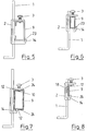
- 5 shows a civil engineering angle on a C-shaped profile rail 9, in which the inclined tab 14 of the civil engineering bracket 2 engages behind the one outer edge 23 of the profile rail 9.
- 1 shows the civil engineering element and 3 the fastening screw.
- Fig. 7 shows a profile rail 9 with a closed rectangular cross-section, in which the opposite two narrow sides 24 of the profile rail 9 is provided with holes 12 for engagement on the one hand the oblique tab 14 and on the other hand for the search tip 10 of the fastening screw 3.
- the civil engineering bracket 2 of the civil engineering bracket provided for fastening engages with its sloping tab 14 behind the one-sided edge 26 of the profile rail 9 and, when the fastening screw 3 is tightened, clamps the civil engineering angle element 1 between the outer surface 18 of the profile rail 9 and the inner side surface 17 of the civil engineering bracket 2 .
- On the narrow side 24 of the profile rail 9 are expedient fixing and Mounting holes 12 are provided for the engagement of the search tip 10 of the mounting screw 3.
- Fig. 9 shows a civil engineering angle, which is provided on a profile rail 9 with a d-shaped cross section.
- the sloping tab 14 of the civil engineering bracket 2 engages there for fastening the civil engineering element 1 behind the one-sided edge 26 of the profile rail 9.
- 3 denotes the fastening screw, the search tip 10 of which is in turn located in fixing and fastening holes 12 on the narrow side 24 of the profile rail 9.
- FIG. 10 shows a civil engineering angle, which is arranged and fastened on a profile rail 9 with a C-shaped cross section.
- the sloping tab 14 of the civil engineering bracket 2 engages behind the one outer edge 23 of the profile rail 9.
- the fastening screw 3 By tightening the fastening screw 3, the civil engineering element 1 is clamped on the one hand between the inner side surface 17 and on the other hand between the profile edges 26 of the profile rail 9.
- the tab 14 can have any suitable pitch angle.
- the tab 14 can be angled at right angles if the angled tab 14 can act on a corresponding bevel 31 on the profile rail 9 for fastening the civil engineering angle.
Abstract
Description
Die Erfindung betrifft einen einstellbaren Tiefbauwinkel für Traggerüste für elektrische Verteileranlagen mit den Merkmalen nach dem Oberbegriff des Patentanspruchs 1.The invention relates to an adjustable civil engineering angle for support structures for electrical distribution systems with the features according to the preamble of
Bei elektrischen Verteileranlagen, insbesondere bei Schalt- und Verteilerschränken sind Traggerüste insbesondere aus C-förmigen vertikal verlaufenden Profilschienen im Einsatz. Für den Einbau von relativ schweren Geräten ist es vorgesehen, sogenannte Geräte-Tragschienen mittels einstellbarer Tiefbauwinkel auf dem Traggerüst aus C-förmigen vertikalen Profilschienen kraftschlüssig lösbar zu befestigen. Dabei ist es erforderlich, daß derartige Tiefbauwinkel nicht nur rationell und wirtschaftlich auf den Profilschienen eines Traggerüstes montierbar, lagenfixierbar und kraftschlüssig befestigbar, sondern auch einfach, insbesondere stufenlos, in der Tiefe verstellbar, sind. Dabei soll sichergestellt sein, daß diese Tiefbauwinkel nicht nur rationell und wirtschaftlich herstellbar, sondern auch auf Profilschienen mit zueinander unterschiedlichem, insbesondere beliebigem, Querschnitt zweckmäßig und zuverlässig einsetzbar sind.In electrical distribution systems, in particular in switchgear and distribution cabinets, support structures, in particular made of C-shaped, vertical profile rails, are used. For the installation of relatively heavy devices, it is provided that so-called device mounting rails are non-positively releasably fastened to the supporting frame from C-shaped vertical profile rails by means of adjustable deep construction angles. It is necessary that such civil engineering angles are not only rationally and economically mountable on the rails of a supporting structure, fixable in position and non-positively fastened, but also simple, in particular steplessly, adjustable in depth. It should be ensured that these civil engineering angles are not only rationally and economically producible, but can also be used expediently and reliably on profile rails with a different, in particular any, cross section.
Ein bekanntgewordener, in der Tiefe einstellbarer, Tiefbauwinkel besteht im wesentlichen aus einem, aus flachbandförmigem Material hergestelltes, rechtwinkeliges Tiefbauwinkelelement, dessen Schenkel unterschiedlich lang sind. Dabei steht der längere Schenkel mit einem, aus zwei Kunststoff-Einzelteilen bestehenden Befestigungselement in Eingriff, bei dem die beiden Einzelteile über schiefe Ebenen zueinander verschiebbar gelagert sind. Dabei ist das Befestigungselement auf der Profilschiene kraftschlüssig befestigt, wobei unter der Wirkung des Schraubbefestigungsmomentes auf die beiden spiegelbildlich formschlüssig aufeinanderliegenden schiefen Ebenen des Befestigungselementes, das dort in Eingriff stehende stufenlos längsverschiebbar gelagerte Tiefbauwinkelelement festgeklemmt wird.A known, adjustable in depth, civil engineering angle consists essentially of a, made of flat strip material, rectangular civil engineering element, the legs of different lengths. The longer leg is in engagement with a fastening element consisting of two plastic individual parts, in which the two individual parts are slidably mounted to one another over inclined planes. The fastening element is non-positively fastened on the profile rail, wherein under the effect of the screw fastening moment on the two mirror-inverted, obliquely superimposed inclined planes of the fastening element, the steplessly displaceable civil engineering angle element engaged there is clamped.
Dieser Tiefbauwinkel ist mit dem Nachteil behaftet, daß die dort zum Einsatz kommenden beiden Kunststoff-Einzelteile nicht nur werkzeugaufwendig und relativ teuer in der Herstellung sind, sondern daß die dort auf den Tiefbauwinkel wirkende Klemmkraft vielfach den auftretenden Dauerbelastungen nicht standhält.This civil engineering angle has the disadvantage that the two plastic individual parts used there are not only tool-intensive and relatively expensive to manufacture, but that the clamping force acting there on the civil engineering angle often does not withstand the continuous loads that occur.
Der Erfindung liegt die Aufgabe zugrunde, einen Tiefbauwinkel der eingangsgenannten Art zu schaffen, bei dem die Nachteile des bekannten Tiefbauwinkel beseitigt sind, und der nicht nur einfach, rationell und wirtschaftlich herstellbar und montierbar ist, sondern der auch auf Tragschienen mit zueinander unterschiedlichem Querschnitt dauerhaft zuverlässig, insbesondere stufenlos einstellbar, kraftschlüssig befestigbar ist.The invention has for its object to provide a civil engineering angle of the type mentioned, in which the disadvantages of the known civil engineering angle are eliminated, and which is not only simple, efficient and economical to manufacture and assemble, but also permanently reliable on mounting rails with different cross-sections , in particular infinitely adjustable, is non-positively attachable.
Diese Aufgabe wird mit den Merkmalen im kennzeichnenden Teil des Patentanspruchs 1 gelöst und in den Unteransprüchen sind weitere vorteilhafte Einzelheiten beansprucht.This object is achieved with the features in the characterizing part of
Vorteilhaft bei diesem Tiefbauwinkel ist nicht nur, daß das Befestigungselement als U-förmiger Tiefbaubügel ausgebildet ist, der insbesondere aus einem rechteckförmigen Flachmaterial geprägt, hergestellt, einerseits mit einer einseitigen, insbesondere rechtwinkelig abgekanteten Befestigungslasche mit dort vorgesehener Befestigungsschraube und andererseits mit einer zur Befestigungslasche hin gerichteten, schräg verlaufend angeordneten, einseitige Lasche, versehen ist, wobei im Abkantbereich der beiden Laschen, zueinander fluchtende Durchbrüche für den Eingriff, die Lagenfixierung und Lagerführung des Tiefbauwinkelelementes vorgesehen sind. Dabei wird beim Anziehen der Befestigungsschraube die schrägverlaufende Lasche hinter einen der Stege oder Kanten der Profilschiene gezogen, sodaß die innen liegende Seite des Tiefbaubügels zur einen äußeren Seite der Profilschiene verschoben wird, wobei das dazwischen liegende Tiefbauwinkelelement kraftschlüssig zwischen dem Tiefbaubügel und der Profilschiene kraftschlüssig lösbar, eingespannt wird. Vorteilhaft ist ferner nicht nur die rationelle und wirtschaftliche Herstellung des Ganzen, sondern auch die einfache, universelle und dauerhaft zuverlässige Montage insbesondere auf C-förmige Profilschienen, sowie die einfache, dort von der Montagevorderseite her durchführbare stufenlose Tiefenverstellung des Tiefbauwinkelementes und dessen kraftschlüssige Befestigung.An advantage of this civil engineering angle is not only that the fastening element is designed as a U-shaped civil engineering bracket, which is made, in particular, of a rectangular flat material, made on the one hand with a one-sided, in particular right-angled fastening tab with the fastening screw provided there, and on the other hand with a fastening bracket directed towards the fastening tab , diagonally arranged, one-sided tab, is provided, with mutually aligned openings for the engagement, the location fixation and bearing guidance of the civil engineering element are provided in the folding area of the two tabs. When the fastening screw is tightened, the sloping tab is pulled behind one of the webs or edges of the profile rail, so that the inner side of the civil engineering bracket is shifted to an outer side of the profile rail, the civil engineering element in between being non-positively detachable between the civil engineering bracket and the profile rail, is clamped. Another advantage is not only the rational and economical production of the whole, but also the simple, universal and durable Reliable installation, especially on C-shaped rails, as well as the simple, infinitely variable depth adjustment of the civil engineering corner element and its frictional attachment.
Einige Ausführungs- und Anwendungsbeispiele sind in den Zeichnungen dargestellt und werden im folgenden näher erläutert. Es zeigen
- Fig. 1
- eine schaubildliche Ansicht der Einzelteile des Tiefbauwinkels,
- Fig. 2
- eine schaubildliche Ansicht des Tiefbauwinkels auf einer Profilschiene, in nichtkraftschlüssiger Montagelage,
- Fig. 3
- eine schaubildliche Ansicht des Tiefbauwinkels auf einer Profilschiene, in kraftschlüssiger Montagelage.
- Fig. 4
- eine schaubildliche Ansicht eines Tiefbauwinkels in einer funktionskonformen Anordnung auf einer Profilschiene eines Traggerüstes,
- Fig. 5
- eine schaubildliche Ansicht des Tiefbauwinkels auf einer C-förmigen Profilschiene,
- Fig. 6
- eine schaubildliche Ansicht des Tiefbauwinkels auf einer Profilschiene mit rechteckförmig geschlossenem Querschnitt,
- Fig. 7
- eine schaubildliche Ansicht des Tiefbauwinkels auf einer Profilschiene mit rechteckförmigem, schmalseitig gelochtem, Querschnitt,
- Fig. 8
- eine schaubildliche Ansicht des Tiefbauwinkels auf einer Winkelprofilschiene,
- Fig. 9
- eine schaubildliche Ansicht des Tiefbauwinkels auf einer d-förmigen Profilschiene,
- Fig. 10
- eine schaubildliche Ansicht des Tiefbauwinkels auf einer C-Profilschiene und
- Fig. 11
- eine schaubildliche Ansicht des Tiefbauwinkels mit einer rechtwinkelig verlaufenden Lasche am Tiefbaubügel, im Eingriff mit einer C-Profilschiene.
- Fig. 1
- a perspective view of the individual parts of the civil engineering angle,
- Fig. 2
- a perspective view of the civil engineering angle on a profile rail, in a non-positive mounting position,
- Fig. 3
- a perspective view of the civil engineering angle on a profile rail, in a non-positive mounting position.
- Fig. 4
- a perspective view of a civil engineering angle in a functionally compliant arrangement on a profile rail of a supporting structure,
- Fig. 5
- a perspective view of the civil engineering angle on a C-shaped rail,
- Fig. 6
- a perspective view of the civil engineering angle on a profile rail with a rectangular closed cross section,
- Fig. 7
- 2 shows a perspective view of the civil engineering angle on a profile rail with a rectangular cross section perforated on the narrow side,
- Fig. 8
- a perspective view of the civil engineering angle on an angle rail,
- Fig. 9
- a perspective view of the civil engineering angle on a D-shaped profile rail,
- Fig. 10
- a perspective view of the civil engineering angle on a C-profile rail and
- Fig. 11
- a perspective view of the civil engineering angle with a right-angled tab on the civil engineering bracket, in engagement with a C-profile rail.
Der, in den Fig. 1 bis 10 dargestellte, insbesondere aus der Fig. 1, in den Einzelteilen ersichtliche, Tiefbauwinkel besteht im einzelnen aus dem Tiefbauwinkelelement 1, das mit dem sogenannten Tiefbaubügel 2 in Eingriff steht und dort längsverschiebbar geführt, in Pfeilrichtung 7, insbesondere stufenlos, einstellbar ist. 3 bezeichnet eine Befestigungsschraube, die mit dem Tiefbaubügel 2 in Eingriff steht.The civil engineering angle, shown in FIGS. 1 to 10, in particular from FIG. 1, which is evident in the individual parts, consists in particular of the civil
Das Tiefbauwinkelement 1 ist insbesondere aus einem flachbandförmigen metallischen Material hergestellt und einseitig mit einer, insbesondere im rechten Winkel abgekanteten, Lasche 4 versehen, in der insbesondere ein Befestigungsloch 5 angeordnet ist. Mindestens auf einer der Oberflächen 6 des Tiefbauwinkelelementes 1 ist eine Markierung 8 zum genauen Einstellen des Tiefbauwinkelelementes 1 gegenüber dem insbesondere U-förmig ausgebildeten Tiefbaubügel 2 vorgesehen, der ebenfalls aus einem rechteckförmigen Flachmaterial geprägt, hergestellt ist. 28 bezeichnet dort die einseitig vorgesehene Befestigungslasche in der ein Gewinde für eine Befestigungsschraube 3 vorgesehen ist. Die Befestigungslasche 28 ist insbesondere im rechten Winkel abgekantet.The civil
Der Befestigungslasche 28 insbesondere parallelverlaufend gegenüberliegend ist eine zur inneren Seitenfläche 17 des Tiefbaubügels 2 angeordnete Abkantung 30 vorgesehen, die mit einer zur Lasche 28 hin gerichteten, schräg verlaufenden, einseitigen Lasche 14 versehen ist.An
Für den Eingriff des Tiefbauwinkelementes 1 im Tiefbaubügel 2 sind im Tiefbaubügel 2, insbesondere im jeweiligen rechtwinkeligen Abkantbereich 29, rechteckig ausgebildete Durchbrüche 20 vorgesehen, für den Durchgriff des mit einem rechteckigen Querschnitt versehenen Tiefbauwinkelelementes 1. Die Durchbrüche 20 sind dort in der Breite etwas größer, als die Dicke des Flachmaterials des Tiefbauwinkelelementes 1.For the engagement of the civil
Aus den Fig. 2 bis 4 ist im wesentlichen die rationelle und zweckmäßige Montage insbesondere auf einer C-förmigen, vertikalen, Profilschiene 9 ersichtlich.From FIGS. 2 to 4, the rational and expedient installation can be seen in particular on a C-shaped, vertical, profiled
Nach Fig. 2 wird zunächst der vormontierte Tiefbauwinkel mit der Befestigungsschraube 3, insbesondere mit der dort vorgesehenen, die Unterseite 11 des Tiefbaubügels 2 leicht überragenden Suchspitze 10 in das den Montageerfordernissen entsprechende Fixier- und Befestigungsloch 12 auf der Vorderseite 13 der Profilschiene 9 eingehängt. Durch Anziehen der Befestigungsschraube 3 wird der Tiefbaubügel 2 mit der, der Befestigungsschraube 3 gegenüber liegend einseitig angeformten, schrägverlaufenden, insbesondere um einen Winkel von ca. 70o geneigten, Lasche 14, in die Nut 15 zwischen den Stegen 16 der Profilschiene 9 gezogen, sodaß die innere Seitenfläche 17 des Tiefbaubügels 2 mit dem dort zwischen der Seitenfläche 17 und der Außenfläche 18 der Profilschiene 9 verlaufend angeordneten Tiefbauwinkelelement 1, im angezogenen Zustand der Befestigungsschraube 5 kraftschlüssig eingeklemmt wird, wie dies aus der Fig. 3 anschaulich ersichtlich ist. Die schrägverlaufende Lasche 14 stützt sich dabei auf der inneren Kante 27 des benachbarten Steges 16 ab.According to FIG. 2, the pre-assembled civil engineering angle is first hung with the
19 zeigt zwei zueinander parallel verlaufend angeordnete Führungslaschen, die am Tiefbaubügel 2 angeformt, zur Profilschiene 9 hin gerichtet sind, zur Lagerführung des Tiefbauwinkelementes 1. Diese Führungslaschen 19 stellen sicher, daß das Tiefbauwinkelement 1 hinreichend präzise, gradlinig im Tiefbaubügel 2 fixiert und geführt ist. Außerdem sind im Bereich der oberseitigen Befestigungslasche 28 des Tiefbaubügels 2, im Bereich der beiden Seitenränder 22, stoffschlüssig nach innen gezogene einseitige Führungsbolzen 23 vorgesehen für den Eingriff in die Fixier- und Befestigungslöcher 12 auf der Vorderseite 13 der Profilschiene 9. Diese Führungsbolzen 23 dienen dort nur der hilfsweisen Montage des Tiefbaubügels auf einer Profilschiene 9. Diese Führungsbolzen 23 kommen außer Eingriff mit den Fixier- und Befestigungslöcher 12, sobald die Befestigungsschraube 3 kraftschlüssig angezogen wird.19 shows two guide lugs arranged parallel to one another, which are formed on the
Die Fig. 5 bis 10 zeigen Montageanordnungen des neuen Tiefbauwinkels auf Profilschienen 9 mit zueinander unterschiedlichen Querschnitten. Dementsprechend sind zu den einzelnen Querschnitten der Profilschienen 9 geringfügig unterschiedliche Abmessungsunterschiede, insbesondere hinsichtlich der einseitigen Länge der schrägverlaufenden Lasche 14 vorgesehen. Die generelle Funktionsweise zur kraftschlüssigen Montage dieses neuen Tiefbauwinkels für die einzelnen Profilschienenquerschnitte ist jedoch in jedem der einzelnen Fälle sichergestellt.5 to 10 show mounting arrangements of the new civil engineering angle on
Die Fig. 5 zeigt einen Tiefbauwinkel auf einer C-förmigen Profilschiene 9, bei der die schrägverlaufende Lasche 14 des Tiefbaubügels 2 hinter die eine Außenkante 23 der Profilschiene 9 greift. 1 zeigt das Tiefbauwinkelelement und 3 die Befestigungsschraube.5 shows a civil engineering angle on a C-shaped
Auch bei der Tiefbauwinkelmontage nach Fig. 6 greift die schrägverlaufende Lasche 14 hinter eine Außenkante 23 der mit einem geschlossenen rechteckigen Querschnitt versehenen Profilschiene 9.6 also engages behind an
Die Fig. 7 zeigt eine Profilschiene 9 mit einem geschlossenen rechteckigen Querschnitt, bei der die einander gegenüberliegenden beiden Schmalseiten 24 der Profilschiene 9 mit Löchern 12 für den Eingriff einerseits der schrägverlaufenden Lasche 14 und andererseits für die Suchspitze 10 der Befestigungsschraube 3 versehen ist.Fig. 7 shows a
Aus der Fig. 8 ist eine Profilschiene 9 mit einem rechtwinkeligen, L-förmigen, Querschnitt ersichtlich. Dabei greift dort der Tiefbaubügel 2 des zur Befestigung vorgesehene Tiefbauwinkels mit seiner schrägverlaufende Lasche 14 hinter die einseitige Kante 26 der Profilschiene 9 und klemmt beim Anziehen der Befestigungsschraube 3 das Tiefbauwinkelelement 1 zwischen die Außenfläche 18 der Profilschiene 9 und die innere Seitenfläche 17 des Tiefbaubügels 2 ein. Auf der Schmalseite 24 der Profilschiene 9 sind zweckmäßigerweise Fixier- und Befestigungslöcher 12 für den Eingriff der Suchspitze 10 der Befestigungsschraube 3 vorgesehen.8 shows a
Die Fig. 9 zeigt einen Tiefbauwinkel, der auf einer Profilschiene 9 mit einem d-förmigen Querschnitt versehen ist. Die schrägverlaufende Lasche 14 des Tiefbaubügels 2 greift dort zur Befestigung des Tiefbauwinkelelementes 1 hinter die einseitige Kante 26 der Profilschiene 9. 3 bezeichnet die Befestigungsschraube, deren Suchspitze 10 wiederum in Fixier- und Befestigungslöcher 12 auf der Schmalseite 24 der Profilschiene 9 steht.Fig. 9 shows a civil engineering angle, which is provided on a
Die Fig. 10 zeigt einen Tiefbauwinkel, der auf einer Profilschiene 9 mit einem C-förmigen Querschnitt angeordnet und befestigt ist. Dabei greift die schrägverlaufende Lasche 14 des Tiefbaubügels 2 hinter die eine Außenkante 23 der Profilschiene 9. Durch das Anziehen der Befestigungsschraube 3 wird das Tiefbauwinkelemenet 1 einerseits zwischen der inneren Seitenfläche 17 und andererseits zwischen den Profilkanten 26 der Profilschiene 9 kraftschlüssig festgeklemmt.10 shows a civil engineering angle, which is arranged and fastened on a
Es liegt im Rahmen der Erfindung, daß die Lasche 14 jeden zweckmäßigen Steigungswinkel aufweisen kann. In diesem Zusammenhange ist es auch vorgesehen, wie dies aus der Fig. 11 ersichtlich ist, daß die Lasche 14 rechtwinkelig abgewinkelt sein kann, wenn die abgewinkelte Lasche 14, zum Befestigen des Tiefbauwinkels, auf eine entsprechende Schräge 31 an der Profilschiene 9 einwirken kann.It is within the scope of the invention that the
Claims (6)
Applications Claiming Priority (2)
| Application Number | Priority Date | Filing Date | Title |
|---|---|---|---|
| DE9403601U | 1994-03-03 | ||
| DE9403601U DE9403601U1 (en) | 1994-03-03 | 1994-03-03 | Civil engineering brackets for scaffolding for electrical distribution systems |
Publications (2)
| Publication Number | Publication Date |
|---|---|
| EP0673094A1 true EP0673094A1 (en) | 1995-09-20 |
| EP0673094B1 EP0673094B1 (en) | 1998-06-03 |
Family
ID=6905439
Family Applications (1)
| Application Number | Title | Priority Date | Filing Date |
|---|---|---|---|
| EP95102463A Expired - Lifetime EP0673094B1 (en) | 1994-03-03 | 1995-02-22 | Angled fitting device for support structures used in distribution systems |
Country Status (4)
| Country | Link |
|---|---|
| EP (1) | EP0673094B1 (en) |
| AT (1) | ATE167005T1 (en) |
| DE (2) | DE9403601U1 (en) |
| ES (1) | ES2116631T3 (en) |
Cited By (4)
| Publication number | Priority date | Publication date | Assignee | Title |
|---|---|---|---|---|
| EP1693937A1 (en) * | 2005-02-22 | 2006-08-23 | Bticino S.P.A. | System for fixing an apparatus-mounting rail to the frame of an electrical control panel |
| DE102006004931A1 (en) * | 2006-02-03 | 2007-08-09 | Robert Bosch Gmbh | cross connector |
| WO2015049338A1 (en) * | 2013-10-02 | 2015-04-09 | Abb Ag | Holding device for a transverse mount in an electrical switchgear cabinet, and a switchgear cabinet |
| WO2015052268A1 (en) * | 2013-10-09 | 2015-04-16 | Abb Ag | Holding device for a lateral mount in an electrical switchgear cabinet, and a switchgear cabinet |
Families Citing this family (3)
| Publication number | Priority date | Publication date | Assignee | Title |
|---|---|---|---|---|
| DE9403601U1 (en) * | 1994-03-03 | 1994-05-26 | Striebel & John Gmbh & Co Kg | Civil engineering brackets for scaffolding for electrical distribution systems |
| DE29619447U1 (en) * | 1996-11-08 | 1997-01-09 | Klinner Joachim | Distribution cabinet with a distribution frame |
| DE10007490C2 (en) * | 2000-02-18 | 2002-04-25 | Rittal Gmbh & Co Kg | Housing for receiving electrical and / or electronic internals |
Citations (4)
| Publication number | Priority date | Publication date | Assignee | Title |
|---|---|---|---|---|
| CH479176A (en) * | 1969-02-25 | 1969-09-30 | Carl Maier & Cie Elek Sche Sch | Support grate for attaching electrical switchgear |
| FR2368812A1 (en) * | 1976-10-21 | 1978-05-19 | Merlin Gerin | Adjustable support rack for electronic equipment - uses toothed racks on upright support posts mating with teeth on pivoted equipment support brackets |
| EP0043559A2 (en) * | 1980-07-04 | 1982-01-13 | Square D Starkstrom GmbH | Device for the mounting of electrical devices above a plate |
| DE9403601U1 (en) * | 1994-03-03 | 1994-05-26 | Striebel & John Gmbh & Co Kg | Civil engineering brackets for scaffolding for electrical distribution systems |
-
1994
- 1994-03-03 DE DE9403601U patent/DE9403601U1/en not_active Expired - Lifetime
-
1995
- 1995-02-22 AT AT95102463T patent/ATE167005T1/en not_active IP Right Cessation
- 1995-02-22 ES ES95102463T patent/ES2116631T3/en not_active Expired - Lifetime
- 1995-02-22 DE DE59502374T patent/DE59502374D1/en not_active Expired - Fee Related
- 1995-02-22 EP EP95102463A patent/EP0673094B1/en not_active Expired - Lifetime
Patent Citations (4)
| Publication number | Priority date | Publication date | Assignee | Title |
|---|---|---|---|---|
| CH479176A (en) * | 1969-02-25 | 1969-09-30 | Carl Maier & Cie Elek Sche Sch | Support grate for attaching electrical switchgear |
| FR2368812A1 (en) * | 1976-10-21 | 1978-05-19 | Merlin Gerin | Adjustable support rack for electronic equipment - uses toothed racks on upright support posts mating with teeth on pivoted equipment support brackets |
| EP0043559A2 (en) * | 1980-07-04 | 1982-01-13 | Square D Starkstrom GmbH | Device for the mounting of electrical devices above a plate |
| DE9403601U1 (en) * | 1994-03-03 | 1994-05-26 | Striebel & John Gmbh & Co Kg | Civil engineering brackets for scaffolding for electrical distribution systems |
Cited By (5)
| Publication number | Priority date | Publication date | Assignee | Title |
|---|---|---|---|---|
| EP1693937A1 (en) * | 2005-02-22 | 2006-08-23 | Bticino S.P.A. | System for fixing an apparatus-mounting rail to the frame of an electrical control panel |
| DE102006004931A1 (en) * | 2006-02-03 | 2007-08-09 | Robert Bosch Gmbh | cross connector |
| WO2015049338A1 (en) * | 2013-10-02 | 2015-04-09 | Abb Ag | Holding device for a transverse mount in an electrical switchgear cabinet, and a switchgear cabinet |
| WO2015052268A1 (en) * | 2013-10-09 | 2015-04-16 | Abb Ag | Holding device for a lateral mount in an electrical switchgear cabinet, and a switchgear cabinet |
| RU2611060C2 (en) * | 2013-10-09 | 2017-02-21 | Абб Аг | Retainer for a crossbeam in an electrical cabinet and cabinet with such a device |
Also Published As
| Publication number | Publication date |
|---|---|
| EP0673094B1 (en) | 1998-06-03 |
| DE9403601U1 (en) | 1994-05-26 |
| ATE167005T1 (en) | 1998-06-15 |
| ES2116631T3 (en) | 1998-07-16 |
| DE59502374D1 (en) | 1998-07-09 |
Similar Documents
| Publication | Publication Date | Title |
|---|---|---|
| EP2009293B1 (en) | Device for connecting a profile rail with another component | |
| DE60304318T2 (en) | ATTACHING A TUBE CLAMP | |
| DE10136681A1 (en) | frame | |
| EP0915310B1 (en) | Mounting of a panel to an appliance door | |
| WO2013097840A1 (en) | Mounting kit for trapezoidal ribs of a trapezoidal sheet | |
| EP3241974B1 (en) | Assembly for a seal, in particular for a contact seal or for an automatically lowerable floor seal for doors | |
| EP0673094B1 (en) | Angled fitting device for support structures used in distribution systems | |
| EP2138069B1 (en) | Component for manufacturing a multi-function writing or work desk | |
| EP2423622A2 (en) | Device for securing a supporting rail | |
| AT403242B (en) | ATTACHMENT FOR A SHOWER CABIN TO A WALL | |
| EP1873340B1 (en) | Door system | |
| EP1243203B1 (en) | Fastening system for slides | |
| DE102010047991A1 (en) | Fastening system for cable transition apparatus in mast, has clips provided with holding part, which is snapped open on rail and connected with transition apparatus, and lateral edges of mast with radial portions run in inner side of mast | |
| EP0609973B1 (en) | Device for fixing of angled coverbrackets | |
| CH650847A5 (en) | Mounting device for fastening on profiled rails having an essentially C-shaped cross-section | |
| AT500181B1 (en) | DOOR OR WINDOW FITTING | |
| DE8504238U1 (en) | Fixing device for a window sill | |
| EP2270403B1 (en) | Solar collector with bearing rail | |
| EP3071896A1 (en) | Holding device for a housing and method for mounting the housing using the holding device | |
| EP0271705A1 (en) | Fastening means for mounting a kitchen sink or suchlike | |
| DE202008015077U1 (en) | Adapter for fixing solar modules, solar modules mounted with adapter and tool for releasing the fastening | |
| DE2707718A1 (en) | BASE CEILING MADE OF PANELS | |
| EP0343416B1 (en) | Suspension rail for signs, plates or thelike, specially as mounting rail for display-panels | |
| DE4309210A1 (en) | Installation element fixed in groove with overhanging edges - incorporates primary hooked part, with flange and support surface | |
| DE202004017344U1 (en) | Adjustable straightening or peeling rail |
Legal Events
| Date | Code | Title | Description |
|---|---|---|---|
| PUAI | Public reference made under article 153(3) epc to a published international application that has entered the european phase |
Free format text: ORIGINAL CODE: 0009012 |
|
| AK | Designated contracting states |
Kind code of ref document: A1 Designated state(s): AT BE CH DE DK ES FR GB GR IE IT LI LU NL PT SE |
|
| 17P | Request for examination filed |
Effective date: 19950927 |
|
| GRAG | Despatch of communication of intention to grant |
Free format text: ORIGINAL CODE: EPIDOS AGRA |
|
| GRAG | Despatch of communication of intention to grant |
Free format text: ORIGINAL CODE: EPIDOS AGRA |
|
| GRAH | Despatch of communication of intention to grant a patent |
Free format text: ORIGINAL CODE: EPIDOS IGRA |
|
| 17Q | First examination report despatched |
Effective date: 19971111 |
|
| GRAH | Despatch of communication of intention to grant a patent |
Free format text: ORIGINAL CODE: EPIDOS IGRA |
|
| GRAA | (expected) grant |
Free format text: ORIGINAL CODE: 0009210 |
|
| AK | Designated contracting states |
Kind code of ref document: B1 Designated state(s): AT BE CH DE DK ES FR GB GR IE IT LI LU NL PT SE |
|
| PG25 | Lapsed in a contracting state [announced via postgrant information from national office to epo] |
Ref country code: IT Free format text: LAPSE BECAUSE OF FAILURE TO SUBMIT A TRANSLATION OF THE DESCRIPTION OR TO PAY THE FEE WITHIN THE PRE;WARNING: LAPSES OF ITALIAN PATENTS WITH EFFECTIVE DATE BEFORE 2007 MAY HAVE OCCURRED AT ANY TIME BEFORE 2007. THE CORRECT EFFECTIVE DATE MAY BE DIFFERENT FROM THE ONE RECORDED.SCRIBED TIME-LIMIT Effective date: 19980603 Ref country code: GR Free format text: LAPSE BECAUSE OF NON-PAYMENT OF DUE FEES Effective date: 19980603 |
|
| REF | Corresponds to: |
Ref document number: 167005 Country of ref document: AT Date of ref document: 19980615 Kind code of ref document: T |
|
| REG | Reference to a national code |
Ref country code: CH Ref legal event code: EP |
|
| REF | Corresponds to: |
Ref document number: 59502374 Country of ref document: DE Date of ref document: 19980709 |
|
| REG | Reference to a national code |
Ref country code: ES Ref legal event code: FG2A Ref document number: 2116631 Country of ref document: ES Kind code of ref document: T3 |
|
| ET | Fr: translation filed | ||
| REG | Reference to a national code |
Ref country code: IE Ref legal event code: FG4D Free format text: GERMAN |
|
| PG25 | Lapsed in a contracting state [announced via postgrant information from national office to epo] |
Ref country code: SE Free format text: LAPSE BECAUSE OF FAILURE TO SUBMIT A TRANSLATION OF THE DESCRIPTION OR TO PAY THE FEE WITHIN THE PRESCRIBED TIME-LIMIT Effective date: 19980903 Ref country code: PT Free format text: LAPSE BECAUSE OF FAILURE TO SUBMIT A TRANSLATION OF THE DESCRIPTION OR TO PAY THE FEE WITHIN THE PRESCRIBED TIME-LIMIT Effective date: 19980903 Ref country code: DK Free format text: LAPSE BECAUSE OF FAILURE TO SUBMIT A TRANSLATION OF THE DESCRIPTION OR TO PAY THE FEE WITHIN THE PRESCRIBED TIME-LIMIT Effective date: 19980903 |
|
| GBT | Gb: translation of ep patent filed (gb section 77(6)(a)/1977) |
Effective date: 19980902 |
|
| PG25 | Lapsed in a contracting state [announced via postgrant information from national office to epo] |
Ref country code: IE Free format text: LAPSE BECAUSE OF NON-PAYMENT OF DUE FEES Effective date: 19990219 |
|
| PG25 | Lapsed in a contracting state [announced via postgrant information from national office to epo] |
Ref country code: LU Free format text: LAPSE BECAUSE OF NON-PAYMENT OF DUE FEES Effective date: 19990222 Ref country code: AT Free format text: LAPSE BECAUSE OF NON-PAYMENT OF DUE FEES Effective date: 19990222 |
|
| PG25 | Lapsed in a contracting state [announced via postgrant information from national office to epo] |
Ref country code: LI Free format text: LAPSE BECAUSE OF NON-PAYMENT OF DUE FEES Effective date: 19990228 Ref country code: CH Free format text: LAPSE BECAUSE OF NON-PAYMENT OF DUE FEES Effective date: 19990228 |
|
| REG | Reference to a national code |
Ref country code: IE Ref legal event code: FD4D |
|
| PLBE | No opposition filed within time limit |
Free format text: ORIGINAL CODE: 0009261 |
|
| STAA | Information on the status of an ep patent application or granted ep patent |
Free format text: STATUS: NO OPPOSITION FILED WITHIN TIME LIMIT |
|
| 26N | No opposition filed | ||
| REG | Reference to a national code |
Ref country code: CH Ref legal event code: PL |
|
| PGFP | Annual fee paid to national office [announced via postgrant information from national office to epo] |
Ref country code: BE Payment date: 19991214 Year of fee payment: 6 |
|
| PGFP | Annual fee paid to national office [announced via postgrant information from national office to epo] |
Ref country code: FR Payment date: 20000120 Year of fee payment: 6 |
|
| PGFP | Annual fee paid to national office [announced via postgrant information from national office to epo] |
Ref country code: ES Payment date: 20000203 Year of fee payment: 6 |
|
| PGFP | Annual fee paid to national office [announced via postgrant information from national office to epo] |
Ref country code: GB Payment date: 20000218 Year of fee payment: 6 |
|
| PGFP | Annual fee paid to national office [announced via postgrant information from national office to epo] |
Ref country code: NL Payment date: 20000229 Year of fee payment: 6 |
|
| PGFP | Annual fee paid to national office [announced via postgrant information from national office to epo] |
Ref country code: DE Payment date: 20000630 Year of fee payment: 6 |
|
| PG25 | Lapsed in a contracting state [announced via postgrant information from national office to epo] |
Ref country code: GB Free format text: LAPSE BECAUSE OF NON-PAYMENT OF DUE FEES Effective date: 20010222 |
|
| PG25 | Lapsed in a contracting state [announced via postgrant information from national office to epo] |
Ref country code: ES Free format text: LAPSE BECAUSE OF NON-PAYMENT OF DUE FEES Effective date: 20010223 |
|
| PG25 | Lapsed in a contracting state [announced via postgrant information from national office to epo] |
Ref country code: BE Free format text: LAPSE BECAUSE OF NON-PAYMENT OF DUE FEES Effective date: 20010228 |
|
| BERE | Be: lapsed |
Owner name: STRIEBEL & JOHN G.M.B.H. & CO. K.G. Effective date: 20010228 |
|
| PG25 | Lapsed in a contracting state [announced via postgrant information from national office to epo] |
Ref country code: NL Free format text: LAPSE BECAUSE OF NON-PAYMENT OF DUE FEES Effective date: 20010901 |
|
| GBPC | Gb: european patent ceased through non-payment of renewal fee |
Effective date: 20010222 |
|
| PG25 | Lapsed in a contracting state [announced via postgrant information from national office to epo] |
Ref country code: FR Free format text: LAPSE BECAUSE OF NON-PAYMENT OF DUE FEES Effective date: 20011031 |
|
| NLV4 | Nl: lapsed or anulled due to non-payment of the annual fee |
Effective date: 20010901 |
|
| REG | Reference to a national code |
Ref country code: FR Ref legal event code: ST |
|
| PG25 | Lapsed in a contracting state [announced via postgrant information from national office to epo] |
Ref country code: DE Free format text: LAPSE BECAUSE OF NON-PAYMENT OF DUE FEES Effective date: 20011201 |
|
| REG | Reference to a national code |
Ref country code: ES Ref legal event code: FD2A Effective date: 20021016 |