EP0671257B1 - Composite board - Google Patents
Composite board Download PDFInfo
- Publication number
- EP0671257B1 EP0671257B1 EP95301624A EP95301624A EP0671257B1 EP 0671257 B1 EP0671257 B1 EP 0671257B1 EP 95301624 A EP95301624 A EP 95301624A EP 95301624 A EP95301624 A EP 95301624A EP 0671257 B1 EP0671257 B1 EP 0671257B1
- Authority
- EP
- European Patent Office
- Prior art keywords
- board
- wood
- reinforcing plate
- resin
- fiber
- Prior art date
- Legal status (The legal status is an assumption and is not a legal conclusion. Google has not performed a legal analysis and makes no representation as to the accuracy of the status listed.)
- Expired - Lifetime
Links
- 239000002131 composite material Substances 0.000 title claims description 46
- 239000002023 wood Substances 0.000 claims description 117
- 230000003014 reinforcing effect Effects 0.000 claims description 99
- 239000000835 fiber Substances 0.000 claims description 58
- 229920005989 resin Polymers 0.000 claims description 38
- 239000011347 resin Substances 0.000 claims description 38
- 239000000463 material Substances 0.000 claims description 35
- 229920005992 thermoplastic resin Polymers 0.000 claims description 33
- 229920006395 saturated elastomer Polymers 0.000 claims description 24
- 239000002245 particle Substances 0.000 claims description 23
- 239000011094 fiberboard Substances 0.000 claims description 14
- 239000007767 bonding agent Substances 0.000 claims description 11
- 239000004568 cement Substances 0.000 claims description 5
- 239000011521 glass Substances 0.000 claims description 5
- 230000001681 protective effect Effects 0.000 claims description 3
- 239000010410 layer Substances 0.000 description 69
- 238000012360 testing method Methods 0.000 description 27
- 238000005304 joining Methods 0.000 description 16
- WSFSSNUMVMOOMR-UHFFFAOYSA-N Formaldehyde Chemical compound O=C WSFSSNUMVMOOMR-UHFFFAOYSA-N 0.000 description 15
- 238000000034 method Methods 0.000 description 15
- -1 polypropylene Polymers 0.000 description 15
- 230000000052 comparative effect Effects 0.000 description 14
- 238000010521 absorption reaction Methods 0.000 description 10
- 239000004743 Polypropylene Substances 0.000 description 9
- 238000005452 bending Methods 0.000 description 9
- 229920001155 polypropylene Polymers 0.000 description 9
- 239000003365 glass fiber Substances 0.000 description 8
- 239000002699 waste material Substances 0.000 description 8
- XLYOFNOQVPJJNP-UHFFFAOYSA-N water Substances O XLYOFNOQVPJJNP-UHFFFAOYSA-N 0.000 description 8
- 239000004567 concrete Substances 0.000 description 7
- 238000010276 construction Methods 0.000 description 7
- 239000004744 fabric Substances 0.000 description 7
- 238000004519 manufacturing process Methods 0.000 description 7
- 238000002844 melting Methods 0.000 description 7
- 230000008018 melting Effects 0.000 description 7
- 239000000203 mixture Substances 0.000 description 7
- 230000007423 decrease Effects 0.000 description 6
- 230000008569 process Effects 0.000 description 5
- 239000011120 plywood Substances 0.000 description 4
- 230000008901 benefit Effects 0.000 description 3
- 238000000748 compression moulding Methods 0.000 description 3
- 238000001816 cooling Methods 0.000 description 3
- 229910052751 metal Inorganic materials 0.000 description 3
- 239000002184 metal Substances 0.000 description 3
- 239000000123 paper Substances 0.000 description 3
- 229920000139 polyethylene terephthalate Polymers 0.000 description 3
- 239000005020 polyethylene terephthalate Substances 0.000 description 3
- 229920005672 polyolefin resin Polymers 0.000 description 3
- 239000002994 raw material Substances 0.000 description 3
- 229920003002 synthetic resin Polymers 0.000 description 3
- 239000000057 synthetic resin Substances 0.000 description 3
- 229920001187 thermosetting polymer Polymers 0.000 description 3
- 241000196324 Embryophyta Species 0.000 description 2
- 239000004698 Polyethylene Substances 0.000 description 2
- 239000004793 Polystyrene Substances 0.000 description 2
- 229920002522 Wood fibre Polymers 0.000 description 2
- 230000008859 change Effects 0.000 description 2
- 230000006835 compression Effects 0.000 description 2
- 238000007906 compression Methods 0.000 description 2
- 230000003247 decreasing effect Effects 0.000 description 2
- 230000002950 deficient Effects 0.000 description 2
- 239000012530 fluid Substances 0.000 description 2
- 239000006260 foam Substances 0.000 description 2
- 239000011888 foil Substances 0.000 description 2
- 239000003292 glue Substances 0.000 description 2
- 230000005484 gravity Effects 0.000 description 2
- 238000010438 heat treatment Methods 0.000 description 2
- 230000006872 improvement Effects 0.000 description 2
- 239000012212 insulator Substances 0.000 description 2
- 229920001684 low density polyethylene Polymers 0.000 description 2
- 239000004702 low-density polyethylene Substances 0.000 description 2
- 238000002156 mixing Methods 0.000 description 2
- 238000000465 moulding Methods 0.000 description 2
- 229920000573 polyethylene Polymers 0.000 description 2
- 229920002223 polystyrene Polymers 0.000 description 2
- 229920005990 polystyrene resin Polymers 0.000 description 2
- 239000004800 polyvinyl chloride Substances 0.000 description 2
- 229920000915 polyvinyl chloride Polymers 0.000 description 2
- 238000012545 processing Methods 0.000 description 2
- 239000012779 reinforcing material Substances 0.000 description 2
- 238000007493 shaping process Methods 0.000 description 2
- 239000007787 solid Substances 0.000 description 2
- 239000002344 surface layer Substances 0.000 description 2
- 239000002025 wood fiber Substances 0.000 description 2
- JZLWSRCQCPAUDP-UHFFFAOYSA-N 1,3,5-triazine-2,4,6-triamine;urea Chemical compound NC(N)=O.NC1=NC(N)=NC(N)=N1 JZLWSRCQCPAUDP-UHFFFAOYSA-N 0.000 description 1
- UXVMQQNJUSDDNG-UHFFFAOYSA-L Calcium chloride Chemical compound [Cl-].[Cl-].[Ca+2] UXVMQQNJUSDDNG-UHFFFAOYSA-L 0.000 description 1
- 229920000049 Carbon (fiber) Polymers 0.000 description 1
- 241000032989 Ipomoea lacunosa Species 0.000 description 1
- 240000007049 Juglans regia Species 0.000 description 1
- 235000009496 Juglans regia Nutrition 0.000 description 1
- 239000004696 Poly ether ether ketone Substances 0.000 description 1
- 239000004695 Polyether sulfone Substances 0.000 description 1
- 239000004734 Polyphenylene sulfide Substances 0.000 description 1
- 229920001131 Pulp (paper) Polymers 0.000 description 1
- BLRPTPMANUNPDV-UHFFFAOYSA-N Silane Chemical compound [SiH4] BLRPTPMANUNPDV-UHFFFAOYSA-N 0.000 description 1
- 229920004738 ULTEM® Polymers 0.000 description 1
- 230000001070 adhesive effect Effects 0.000 description 1
- 230000004075 alteration Effects 0.000 description 1
- 229910052782 aluminium Inorganic materials 0.000 description 1
- XAGFODPZIPBFFR-UHFFFAOYSA-N aluminium Chemical compound [Al] XAGFODPZIPBFFR-UHFFFAOYSA-N 0.000 description 1
- 238000013459 approach Methods 0.000 description 1
- 230000015572 biosynthetic process Effects 0.000 description 1
- 229910001628 calcium chloride Inorganic materials 0.000 description 1
- 239000001110 calcium chloride Substances 0.000 description 1
- 239000004917 carbon fiber Substances 0.000 description 1
- 238000003486 chemical etching Methods 0.000 description 1
- 229920006026 co-polymeric resin Polymers 0.000 description 1
- 239000002826 coolant Substances 0.000 description 1
- 238000003851 corona treatment Methods 0.000 description 1
- 238000005260 corrosion Methods 0.000 description 1
- 230000007797 corrosion Effects 0.000 description 1
- 239000007822 coupling agent Substances 0.000 description 1
- 238000005520 cutting process Methods 0.000 description 1
- 239000000428 dust Substances 0.000 description 1
- 230000003203 everyday effect Effects 0.000 description 1
- 231100000206 health hazard Toxicity 0.000 description 1
- 229920001903 high density polyethylene Polymers 0.000 description 1
- 239000004700 high-density polyethylene Substances 0.000 description 1
- 150000003949 imides Chemical class 0.000 description 1
- 238000007654 immersion Methods 0.000 description 1
- 239000002440 industrial waste Substances 0.000 description 1
- 239000004615 ingredient Substances 0.000 description 1
- 230000010354 integration Effects 0.000 description 1
- 239000004579 marble Substances 0.000 description 1
- 238000005259 measurement Methods 0.000 description 1
- 239000000155 melt Substances 0.000 description 1
- 239000012528 membrane Substances 0.000 description 1
- 238000012986 modification Methods 0.000 description 1
- 230000004048 modification Effects 0.000 description 1
- 238000005192 partition Methods 0.000 description 1
- 230000000704 physical effect Effects 0.000 description 1
- 229920002492 poly(sulfone) Polymers 0.000 description 1
- 229920001707 polybutylene terephthalate Polymers 0.000 description 1
- 239000004417 polycarbonate Substances 0.000 description 1
- 229920000515 polycarbonate Polymers 0.000 description 1
- 229920001225 polyester resin Polymers 0.000 description 1
- 239000004645 polyester resin Substances 0.000 description 1
- 229920006393 polyether sulfone Polymers 0.000 description 1
- 229920002530 polyetherether ketone Polymers 0.000 description 1
- 229920000069 polyphenylene sulfide Polymers 0.000 description 1
- 238000002360 preparation method Methods 0.000 description 1
- 230000002787 reinforcement Effects 0.000 description 1
- 230000004044 response Effects 0.000 description 1
- 238000010079 rubber tapping Methods 0.000 description 1
- 238000009738 saturating Methods 0.000 description 1
- 229910000077 silane Inorganic materials 0.000 description 1
- 239000002356 single layer Substances 0.000 description 1
- 239000002904 solvent Substances 0.000 description 1
- 239000002847 sound insulator Substances 0.000 description 1
- 238000005728 strengthening Methods 0.000 description 1
- 238000012546 transfer Methods 0.000 description 1
- YUYCVXFAYWRXLS-UHFFFAOYSA-N trimethoxysilane Chemical compound CO[SiH](OC)OC YUYCVXFAYWRXLS-UHFFFAOYSA-N 0.000 description 1
- 238000009827 uniform distribution Methods 0.000 description 1
- 235000020234 walnut Nutrition 0.000 description 1
- 238000010792 warming Methods 0.000 description 1
- 210000002268 wool Anatomy 0.000 description 1
Images


Classifications
-
- B—PERFORMING OPERATIONS; TRANSPORTING
- B32—LAYERED PRODUCTS
- B32B—LAYERED PRODUCTS, i.e. PRODUCTS BUILT-UP OF STRATA OF FLAT OR NON-FLAT, e.g. CELLULAR OR HONEYCOMB, FORM
- B32B21/00—Layered products comprising a layer of wood, e.g. wood board, veneer, wood particle board
- B32B21/10—Next to a fibrous or filamentary layer
-
- B—PERFORMING OPERATIONS; TRANSPORTING
- B32—LAYERED PRODUCTS
- B32B—LAYERED PRODUCTS, i.e. PRODUCTS BUILT-UP OF STRATA OF FLAT OR NON-FLAT, e.g. CELLULAR OR HONEYCOMB, FORM
- B32B27/00—Layered products comprising a layer of synthetic resin
- B32B27/04—Layered products comprising a layer of synthetic resin as impregnant, bonding, or embedding substance
-
- B—PERFORMING OPERATIONS; TRANSPORTING
- B32—LAYERED PRODUCTS
- B32B—LAYERED PRODUCTS, i.e. PRODUCTS BUILT-UP OF STRATA OF FLAT OR NON-FLAT, e.g. CELLULAR OR HONEYCOMB, FORM
- B32B21/00—Layered products comprising a layer of wood, e.g. wood board, veneer, wood particle board
- B32B21/02—Layered products comprising a layer of wood, e.g. wood board, veneer, wood particle board the layer being formed of fibres, chips, or particles, e.g. MDF, HDF, OSB, chipboard, particle board, hardboard
-
- B—PERFORMING OPERATIONS; TRANSPORTING
- B32—LAYERED PRODUCTS
- B32B—LAYERED PRODUCTS, i.e. PRODUCTS BUILT-UP OF STRATA OF FLAT OR NON-FLAT, e.g. CELLULAR OR HONEYCOMB, FORM
- B32B21/00—Layered products comprising a layer of wood, e.g. wood board, veneer, wood particle board
- B32B21/04—Layered products comprising a layer of wood, e.g. wood board, veneer, wood particle board comprising wood as the main or only constituent of a layer, which is next to another layer of the same or of a different material
- B32B21/08—Layered products comprising a layer of wood, e.g. wood board, veneer, wood particle board comprising wood as the main or only constituent of a layer, which is next to another layer of the same or of a different material of synthetic resin
-
- B—PERFORMING OPERATIONS; TRANSPORTING
- B32—LAYERED PRODUCTS
- B32B—LAYERED PRODUCTS, i.e. PRODUCTS BUILT-UP OF STRATA OF FLAT OR NON-FLAT, e.g. CELLULAR OR HONEYCOMB, FORM
- B32B37/00—Methods or apparatus for laminating, e.g. by curing or by ultrasonic bonding
-
- B—PERFORMING OPERATIONS; TRANSPORTING
- B32—LAYERED PRODUCTS
- B32B—LAYERED PRODUCTS, i.e. PRODUCTS BUILT-UP OF STRATA OF FLAT OR NON-FLAT, e.g. CELLULAR OR HONEYCOMB, FORM
- B32B5/00—Layered products characterised by the non- homogeneity or physical structure, i.e. comprising a fibrous, filamentary, particulate or foam layer; Layered products characterised by having a layer differing constitutionally or physically in different parts
- B32B5/02—Layered products characterised by the non- homogeneity or physical structure, i.e. comprising a fibrous, filamentary, particulate or foam layer; Layered products characterised by having a layer differing constitutionally or physically in different parts characterised by structural features of a fibrous or filamentary layer
- B32B5/12—Layered products characterised by the non- homogeneity or physical structure, i.e. comprising a fibrous, filamentary, particulate or foam layer; Layered products characterised by having a layer differing constitutionally or physically in different parts characterised by structural features of a fibrous or filamentary layer characterised by the relative arrangement of fibres or filaments of different layers, e.g. the fibres or filaments being parallel or perpendicular to each other
-
- B—PERFORMING OPERATIONS; TRANSPORTING
- B32—LAYERED PRODUCTS
- B32B—LAYERED PRODUCTS, i.e. PRODUCTS BUILT-UP OF STRATA OF FLAT OR NON-FLAT, e.g. CELLULAR OR HONEYCOMB, FORM
- B32B5/00—Layered products characterised by the non- homogeneity or physical structure, i.e. comprising a fibrous, filamentary, particulate or foam layer; Layered products characterised by having a layer differing constitutionally or physically in different parts
- B32B5/14—Layered products characterised by the non- homogeneity or physical structure, i.e. comprising a fibrous, filamentary, particulate or foam layer; Layered products characterised by having a layer differing constitutionally or physically in different parts characterised by a layer differing constitutionally or physically in different parts, e.g. denser near its faces
- B32B5/145—Variation across the thickness of the layer
-
- B—PERFORMING OPERATIONS; TRANSPORTING
- B32—LAYERED PRODUCTS
- B32B—LAYERED PRODUCTS, i.e. PRODUCTS BUILT-UP OF STRATA OF FLAT OR NON-FLAT, e.g. CELLULAR OR HONEYCOMB, FORM
- B32B5/00—Layered products characterised by the non- homogeneity or physical structure, i.e. comprising a fibrous, filamentary, particulate or foam layer; Layered products characterised by having a layer differing constitutionally or physically in different parts
- B32B5/22—Layered products characterised by the non- homogeneity or physical structure, i.e. comprising a fibrous, filamentary, particulate or foam layer; Layered products characterised by having a layer differing constitutionally or physically in different parts characterised by the presence of two or more layers which are next to each other and are fibrous, filamentary, formed of particles or foamed
- B32B5/24—Layered products characterised by the non- homogeneity or physical structure, i.e. comprising a fibrous, filamentary, particulate or foam layer; Layered products characterised by having a layer differing constitutionally or physically in different parts characterised by the presence of two or more layers which are next to each other and are fibrous, filamentary, formed of particles or foamed one layer being a fibrous or filamentary layer
- B32B5/26—Layered products characterised by the non- homogeneity or physical structure, i.e. comprising a fibrous, filamentary, particulate or foam layer; Layered products characterised by having a layer differing constitutionally or physically in different parts characterised by the presence of two or more layers which are next to each other and are fibrous, filamentary, formed of particles or foamed one layer being a fibrous or filamentary layer another layer next to it also being fibrous or filamentary
-
- B—PERFORMING OPERATIONS; TRANSPORTING
- B32—LAYERED PRODUCTS
- B32B—LAYERED PRODUCTS, i.e. PRODUCTS BUILT-UP OF STRATA OF FLAT OR NON-FLAT, e.g. CELLULAR OR HONEYCOMB, FORM
- B32B7/00—Layered products characterised by the relation between layers; Layered products characterised by the relative orientation of features between layers, or by the relative values of a measurable parameter between layers, i.e. products comprising layers having different physical, chemical or physicochemical properties; Layered products characterised by the interconnection of layers
- B32B7/04—Interconnection of layers
- B32B7/12—Interconnection of layers using interposed adhesives or interposed materials with bonding properties
-
- E—FIXED CONSTRUCTIONS
- E04—BUILDING
- E04C—STRUCTURAL ELEMENTS; BUILDING MATERIALS
- E04C2/00—Building elements of relatively thin form for the construction of parts of buildings, e.g. sheet materials, slabs, or panels
- E04C2/02—Building elements of relatively thin form for the construction of parts of buildings, e.g. sheet materials, slabs, or panels characterised by specified materials
- E04C2/10—Building elements of relatively thin form for the construction of parts of buildings, e.g. sheet materials, slabs, or panels characterised by specified materials of wood, fibres, chips, vegetable stems, or the like; of plastics; of foamed products
- E04C2/24—Building elements of relatively thin form for the construction of parts of buildings, e.g. sheet materials, slabs, or panels characterised by specified materials of wood, fibres, chips, vegetable stems, or the like; of plastics; of foamed products laminated and composed of materials covered by two or more of groups E04C2/12, E04C2/16, E04C2/20
-
- G—PHYSICS
- G02—OPTICS
- G02C—SPECTACLES; SUNGLASSES OR GOGGLES INSOFAR AS THEY HAVE THE SAME FEATURES AS SPECTACLES; CONTACT LENSES
- G02C2200/00—Generic mechanical aspects applicable to one or more of the groups G02C1/00 - G02C5/00 and G02C9/00 - G02C13/00 and their subgroups
- G02C2200/14—Laminated frame or frame portions
Definitions
- the present invention relates to wood material, and more specifically relates to composite boards reinforced with fiber-reinforced resin, especially high-strength composite boards used in civil engineering construction and general industry.
- Wood boards made from wood material include plywood board, particle board and fiber board, and are widely used in civil engineering construction work and general industry.
- Plywood boards can be made by taking thick lumber of tropical tree and slicing it into thin slices with a veneer lathe. A plurality of these slices are then stacked and glued together so that their fibers are arranged perpendicular to one another. Another method for making the board is to mix saw dust into glue and have it harden into the shape of a board. Thin slices, as described above, are then glued onto the front and back of this.
- Composite boards of theme types are used in large quantities in civil engineering constructions and the like. However, manufacture of these boards requires a lot of large trees. It takes many years for a tree to grow to an adequate size, even in tropical regions, and cutting down these trees without adequate preparation can destroy a forest. With the recent concern for global warming and desertification, it has become necessary to reduce wood consumption and preserve forests.
- composition boards beside plywood boards include particle boards, fiber boards, wood cement boards, and boards made from wood chips mixed with paper pulp, fiber, and particles of waste material.
- a synthetic resin bonding agent is mixed into plant fibers and hot compression molding is performed. Because there is a uniform distribution of wood fibers, there is no directionality in strength or expansion and compression rates. This gives it the advantage of not splitting or warping during use.
- wood cement boards wood chips, wood scraps and wood wool are processed in a calcium chloride solvent, and then mixed with cement. This is then placed in a mold and compression molding is performed. This allows the material to be formed in thick boards, hollow blocks and the like, and also has the advantages of being a good sound insulator, heat insulator and fire insulator.
- the raw materials for the composition boards described above come from material that would generally have been burned or disposed of as waste, such as miscellaneous small trees, wood scraps, waste wood, and defective wood. These materials are broken into fine pieces and used as fibers or flakes. Waste product from plants of various kinds as well as everyday waste products are also used as raw material. Thus, in composition boards the natural resource of wood is used efficiently, and different kinds of waste products are also recycled into a useful product. Therefore it is expected that composition boards will continue to have increasingly wide usage.
- composition boards described above can be widely used in furniture and structural material in construction, its lack of strength compared to regular composite boards makes it unsuitable for uses such as concrete panels, where an especially high degree of strength is necessary.
- particle boards have inadequate resistance to peeling between particles.
- the material In order to use these in furniture, it is necessary for the material to have a specific gravity of at least 0.65 so that it can maintain adequate strength at the joins. This creates a limitation in production costs and compactness.
- Composition board also has weak supporting strengths for regular wood screws, nails and tapping screws, thus requiring special screws and metal fasteners.
- Composition board can also expand, deform and lose its shape significantly due to humidity or moisture. This makes it inappropriate for allocations that expose it to water.
- this kind of reinforcing material uses a resin that is thermosetting, attempts to increase strength by increasing the fiber content will result in deteriorated resin saturation. Furthermore, it is difficult to make the material thin. These factors put limitations on strength and lightness. Additionally, it is necessary to apply pressure and heat for a long period of time in order to attach the material to wood boards. This makes production difficult and also leads to alterations in the wood board from the heat and pressure.
- thermosetting resins As long as thermosetting resins are used, there is difficulty involved in preventing the warping that accompanies the compression that occurs during hardening.
- the object of the invention is to overcome the drawbacks of the prior art described above.
- Embodiments of the invention desirably provide a high-strength composite board that is based on a wood board that saves precious lumber resources, that prevents water absorption from decreasing expansion, that improves the holding strength of wood screws, and that has mechanical properties that are superior to prior art boards such as lightness, strength, rigidity, and lifespan.
- Embodiments of the invention may also have a lower emission of formalin, thus making them safer.
- a composite board comprising:
- Boards containing wooden scraps and fiber include boards made by mixing, pressurizing and molding wood scraps and wood fiber combined with a bonding agent and small particles from various waste products.
- the surface of the wood board to which the reinforcing plate will be joined is saturated to a depth of 0.1-1 mm with the same thermoplastic resin that is saturated in the reinforcing plate.
- the reinforcing plate may then be glued to the resin-saturated layer. Also it, would be desirable to mix in short fibers with the resin-saturated layer.
- the reinforcing plate is made by stacking a plurality of single layers (prepreg sheets) so that the fibers are oriented in different directions. It would be desirable to have been two and four layers of prepreg.
- thermoplate resin plate made from the same resin used in the reinforcing plate, on the surface or an inner layer of the reinforcing plate.
- a layer comprising an embossed surface sheet, a decorative material or the like is attached to the surface, and then a protective resin film is attached on top of that.
- the protective film may be temporarily attached.
- FIG. 1 there is shown a flat high-strength composite board 1A appropriate for use in concrete frames and the like. Reinforcing plates 12, 13 are attached integrally to the front and back sides of wood board 11 through thermal adhesion. A resin-saturated layer on the surface of wood board 11 is formed by saturating the thermoplastic resin used in reinforcing plates 12, 13.
- Reinforcing plates 12, 13 comprise a stack of prepreg sheets.
- the prepreg sheets are made by arranging long continuous fibers in one direction and mixing thermoplastic resin so that the weight ratio to the fibers is between 40 percent and 80 percent. It would be desirable to have between two and four sheets stacked so that the orientation of the fibers are different.
- Heat is applied in order to attach wood board 11 and reinforcing plates 12, 13.
- the minimum temperature for this is the melting point of the thermoplastic resin saturated in the reinforcing plates. While the resin is molten the plates are put on wood board 11.
- the pieces are joined by cooling at a pressure of 3 kg/cm 2 or less using a press.
- thermoplastic resin penetrates through the surface into the spaces between wood particles or the like, and surrounds the wood particles. This forms a resin-saturated layer 15.
- resin-saturated layer 15 When the resin cools off and becomes solid, wood board 11 and reinforcing plates 12, 13 form a firm bond via resin-saturated layer 15.
- FIG. 5 there is shown details of the resin-saturated layer.
- large particles 11-1 which make up the core section of wood board 11.
- Smaller particles 11-2 are present at the surface layer.
- Reinforcing plate 12 comprises a prepreg 12-1 and a prepreg 12-2, which are stacked so that their fiber orientations are perpendicular to each other.
- Thermoplastic resin 16 is resin that has penetrated into wood board 11 from reinforcing plate 12.
- thermoplastic resin fills up the spaces between the fibers distributed in reinforcing plate 12, and at the same time, fills up the spaces between the particles that make up wood board 11, thus making them integral. This results in a strong bond between wood board 11 and reinforcing plate 12, 13.
- the thickness of resin--saturated layer 15, i.e. the saturation depth of the resin it would be desirable for the thickness of resin--saturated layer 15, i.e. the saturation depth of the resin, to be between 0.1 mm and 1 mm. In cases when resin-saturated layer 15 is not adequately formed or when the saturation depth is 0.1 mm or less, the bonding strength decreases significantly. On the other hand, it is difficult to have a depth greater than 1 mm, and a resin-saturated layer that is so thick would not increases bonding strength anyway.
- a plurality of short fibers 17 is distributed at the surface of wood board 11. This results in an even greater bonding strength because short fibers 17 become entangled with the glass fibers in reinforcing plate 12.
- thermoplastic resin Before bonding reinforcing plate 12, it would be desirable to preheat wood board 11 to a temperature high enough to allow the thermoplastic resin to flow. This is so that the flowing resin can effectively fill the spaces in wood board 11, thus providing an adequate thickness for resin-saturated layer 15.
- FIG. 2 there is shown an embodiment of the high-strength composite board of the present invention, in which there is a bent board 1b having an arcuate cross-section.
- reinforcing plates 12, 13 are bonded to wood board 11, which has been bent.
- This embodiment is appropriate for curved concrete panels and the like.
- reinforcing plates 12, 13 When the vertical and horizontal dimensions of wood board 11 and reinforcing plate 12, 13 are identical, it is possible for reinforcing plates 12, 13 to be peeled off at the corners.
- reinforcing plate 12 having vertical and horizontal dimensions that are somewhat smaller than those of wood board 11. In a high-strength composite board 1c configured in this manner, reinforcing plate 12 does not peel off from the corner of wood board 11, thus allowing easier handling.
- reinforcing plate 12 Another way to prevent reinforcing plate 12 from being peeled off from the edges of wood board 11 would be to have reinforcing plate 12 be larger than wood board 11. The ends of reinforcing plate 12 would be bent over to cover wood board 11. With this configuration, the ends of wood board 11 would be covered by reinforcing plate 12, thus increasing the overall strength of the composite board as well as increasing the local strength at the corners. This prevents reinforcing plate 12 from being peeled off.
- FIG. 4 there is shown a composite board 10. Reinforcing plates 12 and 13 are bonded to the front and back of wood board 11. A surface material 14 is attached to the surface of front reinforcing plate 12.
- surface material 14 improves the mold release characteristics relative to the concrete. It is possible to use a surface material that is smooth when the concrete is to be smooth or polished. It is also possible to use an embossed material in order to provide designs on the front of a building, thus increasing its aesthetic qualities.
- surface material 14 can be used to transfer various designs and patterns on to concrete, such as wood grain, marble, brushstrokes, line art, and the like.
- surface material 14 can be paper prints of wood grain, thin wooden plates, and the like.
- a weather-resistant material would be used, such as a resin membrane or a metal foil.
- the thin thermoplastic resin layer formed on the reinforcing plate is not especially attractive, it is possible to apply a bonding agent to this surface and attach a decorative surface material to the surface.
- the bonding agent may not be able to form an effective bond, preventing an adequate bonding strength.
- obtaining an adequate bonding strength may require processing of the reinforcing plate surface by sanding, corona discharge treatment, chemical etching and the like. These types of processing considerably increases production costs.
- thermoplastic resin used in the reinforcing plate is not particularly specified.
- the following can be used: polystyrene, polyvinyl chloride, straight-chain low-density polyethylene, low-density polyethylene, high-density polyethylene, polypropylene, polycarbonate, polybutylene terephthalate, polyethylene terephthalate, polyether sulfone, polysulfone, polyethyl imide (trade name: ULTEM), polyether ether ketone, polyphenylene sulfide, and the like.
- the optimal resin would be the generally used polyolefin resins and the polystyrene resins such as polyethylene and polypropylene.
- the long continuous fibers are mixed at a ratio of 40-80 percent by weight. It would be especially desirable to have a ratio of 45-70 percent by weight. If the ratio is less than 40 percent, the molding of the reinforcing plate become difficult because of the increased fluidity of the resin a high temperatures. In addition, it becomes difficult to obtain the rigidity and wear resistance required for a board. Also if the ratio goes beyond 80 percent, the adhesive properties decrease and shaping becomes difficult.
- the continuous long fibers in the reinforcing plate are arranged in a single direction and in a direction that would generally receive bending stress darting use.
- the prepreg layers used in the reinforcing plate can be made according to the method disclosed in Japanese Laid-open Patent Publication No. 2-42168.
- monofilament glass fibers used for strengthening are processed with a coupling agent, such as ⁇ -methacryloxpropyl trimethoxy silane.
- a coupling agent such as ⁇ -methacryloxpropyl trimethoxy silane.
- a bundle of a plurality of yarns is pulled with a fixed tension and brought into contact with molten thermoplastic resin. Resin is penetrated inside the yarn while being put through a heated roller.
- the composite boards of the invention two or more layers of prepreg are stacked.
- a reinforcing plate is attached to only one side of a wood board and the reinforcing plate is too thick, it is possible for the the composite board to warp.
- a single prepreg layer should be between 50 and 600 micrometers, and also, it would be desirable to keep the total thickness at 1 mm or less even when between 2 and 4 layers are stacked together.
- the composite board can also warp, if the reinforcing plate has a large coefficient of thermal expansion. This is why the coefficient of thermal expansion is kept at 10 -5 / °C or less.
- Examples of material that can be used for the surface material include; foam or non-foam sheets such as polypropylene, polystyrene sheets; thermoplastic resin products such as PVC, PZT sheets; metal foil; paper; woven and non-woven cloths made from various fibers.
- foam or non-foam sheets such as polypropylene, polystyrene sheets
- thermoplastic resin products such as PVC, PZT sheets
- metal foil such as PVC, PZT sheets
- metal foil such as PVC, PZT sheets
- paper woven and non-woven cloths made from various fibers.
- the procedure involves heating the reinforcing plates comprising continuous long fibers and thermoplastic resin to a temperature at or above the melting point of the thermoplastic resin. They are then placed on the front and back sides of the wood board. Pressure is applied through a press roller, and the board is shaped. A surface material is bonded to the surface, if necessary.
- Another method provides a more reliable bond using thermal bonding.
- Both the reinforcing plate and the wood board is heated to a temperature around the melting point of the resin in the reinforcing plate. Then the reinforcing plate and the wood board and put together.
- a press that is heated between room temperature and 80 °C is used to apply pressure between 0.1 kg/cm 2 and 3 kg/cm 2 .
- thermoplastic resin layer containing short fibers between the wood board and the reinforcing plate thus having the short fibers connecting the two during bonding.
- the short fibers used here a length of between 0.1 mm and 100 mm.
- the desirable length for the short fibers is between 0.5 mm and 20 mm.
- the short fibers can be, for example, polyolefin resin fibers, polyester resin fibers, glass fibers, non-woven cloth and the like.
- thermoplastic resin layer containing these layers is formed so that it uniformly covers the surface of the wood board. It would also be possible to cover the surface of the wood board with chopped thermoplastic resin containing glass fibers.
- thermoplastic resin When the thermoplastic resin is heated to the melting point or above, it generally melts into a fluid state. However, in composite material containing 40 percent by weight or more of fibers, the resin is prevented from flowing freely within the fiber lattice. When pressure is applied for shaping, the overall shape is kept uniform as a result of the fiber structure, even if the fiber structure is changed. Thus, resin is prevented from leaking out and a high quality, precise shape is obtained.
- the reinforcing plate and the wood board must be made integral while the thermoplastic resin in the reinforcing plate is in a molten state. It is therefore necessary to have a device that can go from the heating step to the cooling and integration step in a short period of time.
- FIG. 7 there is shown as example of such a device for making high-strength composite boards.
- the device comprises: a hot press 20 for preheating the wood board; a hot press 30 for preheating the reinforcing plate; and a joining press 40 for cooling and bonding.
- Wood board 11 produced by a press for making wood boards (not shown in the drawings), is heated by wood board preheating hot press 20 so that at least its surface has a temperature around the melting point of the thermoplastic resin used in reinforcing plates 12, 13.
- reinforcing plates 12, 13, produced by a press for making reinforcing plates(not shown in the drawings) is heated by reinforcing plate preheating hot press 30 to a temperature at or higher than the melting point of the thermoplastic resin used in its production. Reinforcing plates 12 and 13 are protected on both sides by removable sheets 22.
- Removable sheet 22 on the upper surface of reinforcing plate 12 is removed by a device not shown in the drawings. Then the plate is placed on the die of joining press 40 by a conveyor device not shown in the drawings.
- wood board 11 is placed on the plate by a conveyor device not shown in the drawings.
- a different conveyor device not shown in the drawings carries reinforcing plate 13 to joining press 40. While it is being carried, removable sheet 22 on the lower surface of the plate is removed, and then the plate is placed on wood board 11.
- THe punch of the joining press descends and applied pressure on reinforcing plates 12 and 13 as well as wood board 11 between them.
- the die and the punch of the joining press contain fluid channels 41 for the circulation of coolants.
- the die and punch are kept consistently at a temperature considerably lower than the melting point of the thermoplastic resin. This cools reinforcing plates 12 and 13 and wood board 11 between them.
- the thermoplastic resin and the high-strength composite board is completed.
- the prepreg layers used in these test sample were all made according to the method disclosed in Japanese Laid-open Patent Publication No. 2-42168 described above.
- the glass fibers used in the tests are monofilaments 13 micrometers thick and are processed with ⁇ -methacyloxypropyltrimethoxy silane. 1,800 fibers are bundled into yarn having no twists. The yarn is pulled with a fixed tension and aligned in a single direction.
- the prepreg layer is formed by having resin penetrate into yarn using a heated roller rubbing resin in.
- the prepreg layer is formed by having resin penetrate into the yarn using a heated roller rubbing resin in. Prepreg made in this way provide good adhesion between the thermoplastic resin and the fiber.
- the fiber content can be varied between 40 percent and 80 percent by weight as necessary, and the thickness can be between 0.01 mm and 1 mm.
- the reinforcing plates can be formed from a single prepreg layer, or then can be formed by stacking two prepreg layers so that the fiber orientations are perpendicular to each other.
- Prepregs A-C and E have fiber content of between 40 percent and 80 percent by weight, and relate to the present invention.
- Prepreg F and prepreg G are outside this range and are used in the tests as comparative embodiments.
- CONFIGURATION OF PREPREGS Symbol Fiber Resin Fiber Content (wt %) Thickness (mm) Weight per unit area (kg/m 2 )
- the tests used particle board, and fiber board as the wood boards Referring to Table 2, there is shown descriptions of the wood boards used.
- Each of the wood boards were cut into 500 mm square prepregs having a length of 500 mm and width 500 mm were cut out in pairs.
- the reinforcing plates were formed by bonding together two prepregs in a pair so that their fiber orientations were perpendicular.
- CONFIGURATION OF WOOD BOARDS Symbol Configuration Specific Gravity Thickness (mm)
- PN Triple-layered particle board - 12 PO Triple-layered particle board - 8 FN Medium-fiber board 0.6 12 FO Medium-fiber board 0.5 9 FP Soft-fiber board 0.3 12
- a device for making high-strength composite boards Referring to Fig. 7, there is shown a device for making high-strength composite boards.
- the die and the punch of hot press 20, hot press 30 and joining press 40 are heated to 100°C , 200 °C and 70 °C lespectively.
- Pressure is applied from hot press 20 at 3 kg/cm 2 for two minutes.
- the reinforcing plates are covered on both sides with a peeling film 22.
- a pressure of 0.1 kg/cm 2 is while the plates are preheated for two minutes.
- Pressure is applied from joining press 40 for one minute at 1 kg/cm 2 .
- test sample The structure and materials of the test sample used are as shown in table 3.
- a "+" symbol in the prepreg column indicates that two layers of prepreg having perpendicular fiber orientations were used.
- a removable sheet from one of the reinforcing plates is peeled off during the joining process at the joining press, and a 0.2 mm thick non-woven cloth made from polyethylene terephthalate is attached as surface material. And after joining, a bonding agent is applied to the surface of the non-woven cloth, and a thin walnut plate 0.2 mm thick is attached.
- a non-stretching polypropylene resin film 100 micrometers thick is interposed between the reinforcing plates and the front and back sides of the wood board.
- a non-woven cloth 0.5 mm thick made from glass fiber 17 micrometers thick is interposed between the reinforcing plates and the front and back sides of the wood board.
- a non-woven cloth made from polyethylene terephthalate 0.2 mm thick is interposed between the reinforcing plates and the front and back sides of the wood board.
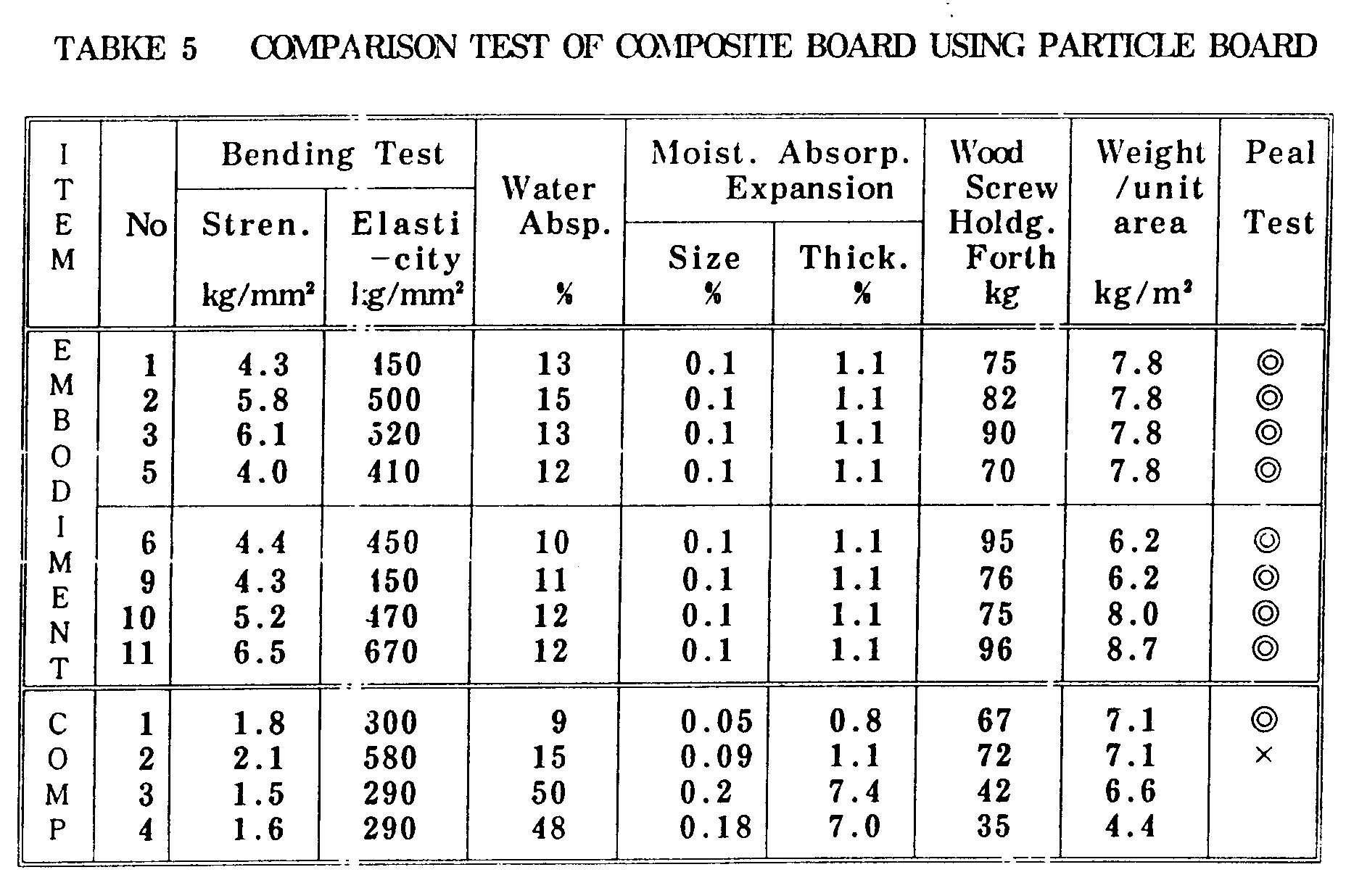
- Test for bending properties JIS A5908. Measurement of bending strength and bending elasticity.
- Breaking load performed only for samples comprising plywood only.
- Water absorption test JIS A5908. After 24 hours of immersion in water, the water absorption rate, the change in dimensions due to moisture absorption and the change in thickness due to moisture absorption are measured.
- Wood screw holding strength JIS A5908. Performed on embodiments 1 to 11 and comparative embodiments 1 to 4.
- Formalin test Comparison using embodiments 1, and 12 and the wood boards used in these embodiments.
- Peeling test Test to observe if peeling occurs or not at the bonding surface between the wood board and the reinforcing plate.
- a double circle mark o ⁇ in the peeling test column indicates that there was no peeling at the thermal adhesion layer, and that there was internal breakage in the wood board.
- a cross mark X indicates that there was peeling at the thermal adhesion layer.
- the high strength composite board of the present invention has a bending strength three to four times that of particle board. Bending elasticity is stronger by a factor of 1.5 to 2.
- reinforcing plates are arranged on both sides, water absorption decreases 1/3 to 1/5, expansion due to moisture absorption decreases by half, and expansion of thickness is less than 1/6.
- wood screw holding strength increases by about a factor of two.
- the high-strength composite board of the present invention has a bending strength three to four times that of fiber board. Bending elasticity is stronger by a factor of 1.5 to 2.
- water absorption decreases 1/3 to 1/5
- expansion due to moisture absorption decreases by half
- expansion of thickness is less than 1/6.
- the high-quality and high-strength wood board of the present invention is lighter, allows easier on-site handling, requires fewer raw materials, and higher compressive strength.
- the board has a very high overall rigidity, and its use can result in an extremely solid construction.
Landscapes
- Engineering & Computer Science (AREA)
- Life Sciences & Earth Sciences (AREA)
- Wood Science & Technology (AREA)
- Architecture (AREA)
- Civil Engineering (AREA)
- Structural Engineering (AREA)
- Laminated Bodies (AREA)
Description
| CONFIGURATION OF PREPREGS | |||||
| Symbol | Fiber | Resin | Fiber Content (wt %) | Thickness (mm) | Weight per unit area (kg/m2) |
| A | Glass | Polypropylene | 50 | 0.20 | 0.3 |
| B | Glass | Polypropylene | 53 | 0.20 | 0.3 |
| C | Glass | Polypropylene | 85 | 0.20 | 0.3 |
| E | Glass | Polyethylene | 50 | 0.20 | 0.3 |
| F | Glass | Polypropylene | 28 | 0.20 | 0.3 |
| G | Glass | Polypropylene | 90 | 0.20 | 0.3 |
| CONFIGURATION OF WOOD BOARDS | |||
| Symbol | Configuration | Specific Gravity | Thickness (mm) |
| PN | Triple-layered particle board | - | 12 |
| PO | Triple-layered particle board | - | 8 |
| FN | Medium-fiber board | 0.6 | 12 |
| FO | Medium-fiber board | 0.5 | 9 |
| FP | Soft-fiber board | 0.3 | 12 |
| CONFIGURATIONS & MATERIAL OF COMPOSITE BOARDS | |||||
| Embodiment No. | Wood board symbol | Prepreg | Reinforcement Place | Resin-saturated Layer (mm) | Notes |
| 1 | PIN | A+ 2 layers | Both sides | 0.4 | |
| 2 | PN | B+ 2 layers | Both sides | 0.2 | |
| 3 | PN | C+ 2 layers | Both sides | 0.1 | |
| 5 | PN | E+ 2 layers | Both sides | 0.3 | |
| 6 | PO | A+ 2 layers | Both sides | 0.4 | |
| 9 | PO | A+ 2 layers | Both sides | 0.4 |  |
| 10 | PO | A+ 2 layers | Both | 1 |  |
| 11 | PO | A+ 2 layers | Both sides | 0.4 |  |
| 12 | FN | A+ 2 layers | Both sides | 0.4 | |
| 13 | FN | B+ 2 layers | Both sides | 0.2 | |
| 14 | FN | C+ 2 layers | Both sides | 0.1 | |
| 16 | FN | E+ 2 layers | Both sides | 0.3 | |
| 17 | FO | A+ 2 layers | Both sides | 0.4 | |
| 18 | FP | A+ 2 layers | Both sides | 0.4 | |
| 21 | FN | A+ 2 layers | Both sides | 0.4 | |
| 22 | FN | A+ 2 layers | Both sides | 0.8 | |
| 23 | FN | A+ 2 layers | Both sides | 0.2 | ▴ |
| CONFIGURATION & MATERIALS OF BOARDS OF COMPARATIVE EMBODIMENTS | |||||
| No. | Wood Board Symbol | Prepreg | Reinforcing Plate | Resin-saturation Layer (mm) | |
| 1 | PN | F+ 2 layers | Both sides | 0.5 | |
| 2 | PN | G+ 2 layers | Both sides | < 0.1 | |
| 3 | PN | not used | board only | ||
| 4 | PO | not used | board only | ||
| 5 | FN | F+ 2 layers | Both sides | 0.5 | |
| 6 | FN | G+ 2 layers | Both sides | < 0.1 | |
| 7 | FN | not used | board only | ||
| 8 | FO | not used | board only | ||
| 9 | FP | not used | board only |

| RESULTS OF FORMALIN COMPARISON TEST | |||
| Item | Wood board | Prepreg | |
| Embodiment | |||
| 1 | PN | A+ 2 layers | 3.4 |
| Comp. | PN | None | 6.5 |
| | FN | A+ 2 layers | 2.8 |
| Comp. Embodiment 7 | FN | None | 6.2 |
Claims (7)
- A composite board comprising:a reinforcing plate comprising a plurality of layers of glass fiber-reinforced thermoplastic resin joined to a wood board wherein:long continuos fibers are arranged in a single direction within each layer of said glass fiber-reinforced thermoplastic resin, different layers having different fiber alignments, and the thermal expansion coefficient of each layer, in the direction of the fibers in that layer being 10-5/°C or lower; and the ratio by weight of said long continuous fibers is between 40 percent and 80 percent of the fiber-reinforced resin;the thermoplastic resin contained in said reinforcing plate is saturated to a depth of between 0.1mm and 1mm into a surface of said wood board to which said reinforcing plate is attached; andsaid wood board is a particle board, a fiber board, wood cement board, or a composite board containing wooden scraps and fiber on which is applied a bonding agent.
- A composite board according to claim 1 wherein said resin-saturated layer on a surface of said wood board contains short fibers
- A composite according to claim 1 or claim 2 wherein:said plurality of layers of said reinforcing plate comprises between two and four layers.
- A composite board according to any one of the preceding claims wherein:at least one reinforcing plate is larger in size than said wood board; and the ends of said wood board are covered by the surplus area of said reinforcing plate or plates.
- A composite board according to any one of the preceding claims wherein:at least one of the surfaces has a surface material.
- A composite board according to claim 5 wherein:said surface material is larger in size than said composite board; and the ends of said composite board are covered by the surplus area of said surface material.
- A composite board according to any one of the preceding claims wherein:a protective resin film is attached to at least one of the surfaces.
Applications Claiming Priority (6)
| Application Number | Priority Date | Filing Date | Title |
|---|---|---|---|
| JP4027594 | 1994-03-11 | ||
| JP4027994 | 1994-03-11 | ||
| JP40275/94 | 1994-03-11 | ||
| JP40279/94 | 1994-03-11 | ||
| JP48110/94 | 1994-03-18 | ||
| JP4811094 | 1994-03-18 |
Publications (3)
| Publication Number | Publication Date |
|---|---|
| EP0671257A2 EP0671257A2 (en) | 1995-09-13 |
| EP0671257A3 EP0671257A3 (en) | 1996-05-15 |
| EP0671257B1 true EP0671257B1 (en) | 1998-11-11 |
Family
ID=27290422
Family Applications (1)
| Application Number | Title | Priority Date | Filing Date |
|---|---|---|---|
| EP95301624A Expired - Lifetime EP0671257B1 (en) | 1994-03-11 | 1995-03-13 | Composite board |
Country Status (8)
| Country | Link |
|---|---|
| EP (1) | EP0671257B1 (en) |
| KR (1) | KR0164926B1 (en) |
| CN (1) | CN1067016C (en) |
| CA (1) | CA2144207C (en) |
| DE (1) | DE69505863T2 (en) |
| MY (1) | MY114262A (en) |
| SG (1) | SG59907A1 (en) |
| TW (1) | TW279147B (en) |
Cited By (1)
| Publication number | Priority date | Publication date | Assignee | Title |
|---|---|---|---|---|
| CN104278834A (en) * | 2014-10-14 | 2015-01-14 | 吉林吉电能源有限公司 | Two-in-one plastic-wooden composite building formwork |
Families Citing this family (24)
| Publication number | Priority date | Publication date | Assignee | Title |
|---|---|---|---|---|
| AU4546697A (en) * | 1997-07-16 | 1999-02-10 | Azizollah Ghassemi | Coated building material |
| WO2001070498A1 (en) * | 2000-03-22 | 2001-09-27 | Werner Dreier | Thermoformable composite material |
| FI5810U1 (en) * | 2002-02-25 | 2003-06-06 | Isku Oy | shelf |
| DE10254757A1 (en) * | 2002-11-02 | 2004-05-19 | SCHAPER, Jörg | Base for wood decking, consists of a thermoplastic laminar material, with a channel structure on its lower side |
| EP1570984A1 (en) * | 2004-03-01 | 2005-09-07 | Kemlite Company, Inc. | Lighter-weight reinforced decorative composite material |
| DE102007054711B4 (en) | 2007-11-14 | 2014-12-04 | Fritz Egger Gmbh & Co. Og | Method for producing a thin chipboard with increased stability and thin chipboard with increased stability |
| CN101315449B (en) * | 2008-07-11 | 2010-04-07 | 宁波华缘玻璃钢电器制造有限公司 | Optical fiber cable section box board and its shaping method |
| US20110126683A1 (en) * | 2009-11-30 | 2011-06-02 | Raymond Dueck | Rotary Sheet Metal Cutter |
| CN102127964B (en) * | 2011-01-05 | 2012-07-25 | 江苏奇一科技有限公司 | Building template reinforced by composite of continuous fiber plastic coated belt material and preparation method thereof |
| ITBL20120002A1 (en) * | 2012-03-30 | 2013-10-01 | Wolf Di Damiano Da Rold E Fiorenzo Barp S N C | METHOD OF MANUFACTURE OF WOODEN AND CARBON FIBER FRAMES, MULTI-LAYER. |
| CN103568081B (en) * | 2012-07-19 | 2018-01-16 | 上海杰事杰新材料(集团)股份有限公司 | A kind of laminate and its preparation method and application |
| CN103410308B (en) * | 2013-06-28 | 2017-02-08 | 句容市百事特复合材料有限公司 | Plastic formwork of LFT material strip fabric reinforcing core layer and producing method thereof |
| CN104453214A (en) * | 2013-09-16 | 2015-03-25 | 辽宁辽杰科技有限公司 | Laminated plate and manufacturing method thereof for building template |
| CN104032845A (en) * | 2014-06-26 | 2014-09-10 | 东华大学 | Flame-retardant and sound-absorbing plate |
| KR101675407B1 (en) | 2015-07-10 | 2016-11-14 | 주식회사 엔에프인더스 | method of manufacturing plywood |
| CN109016565A (en) * | 2017-06-12 | 2018-12-18 | 科思创德国股份有限公司 | It is used to prepare the pultrusion method and equipment of fibre reinforced composites |
| CN110485238A (en) * | 2019-07-11 | 2019-11-22 | 上海市政工程设计研究总院(集团)有限公司 | A kind of fabricated permeable pavement concrete slab |
| CN112351606B (en) * | 2020-10-13 | 2022-04-08 | 安庆柯麦机电科技有限公司 | Substrate pretreatment equipment of 5G cabinet |
| CN114643723A (en) * | 2020-12-21 | 2022-06-21 | 中冶建筑研究总院有限公司 | Three-dimensional woven fiber composite board and preparation method thereof |
| CN114603877B (en) * | 2022-03-07 | 2022-09-30 | 普洱林达木业有限责任公司 | Production process and equipment of environment-friendly composite board |
| CN114643462B (en) * | 2022-05-20 | 2022-08-16 | 太原理工大学 | A kind of titanium alloy/stainless steel composite plate and preparation method thereof |
| CN116423857B (en) * | 2023-06-13 | 2023-08-18 | 江苏科美声学科技有限公司 | Sound insulation board production device, microcrystal damping type environment-friendly sound insulation board and production process |
| EP4603277A1 (en) * | 2024-02-14 | 2025-08-20 | Mardello Italia S.r.l.s. | Multilayer panel for wooden construction |
| CN118682872A (en) * | 2024-05-27 | 2024-09-24 | 北京林业大学 | A method for preparing a high thermal conductivity laminate floor substrate |
Family Cites Families (6)
| Publication number | Priority date | Publication date | Assignee | Title |
|---|---|---|---|---|
| GB1423046A (en) * | 1973-05-05 | 1976-01-28 | Dunlop Ltd | Sports rackets |
| GB2053696A (en) * | 1979-07-18 | 1981-02-11 | Grays Of Cambridge Internation | Carbon fibre laminated sports equipment |
| US4416929A (en) * | 1981-07-02 | 1983-11-22 | Proform, Inc. | Multilayer stitched knitted fiberglass composite |
| DE4110640A1 (en) * | 1990-04-05 | 1991-10-10 | Richard Pott | Laminate FRP construction wood prods. - consists of e.g. veneer or chipboard bonded to unidirectional or crossed fibre FRP in the form of e.g. three, four or more ply boards |
| CN1066020A (en) * | 1991-04-21 | 1992-11-11 | 孔庆翔 | Utilize glass fibre to produce the method for moulded parts |
| CN2121313U (en) * | 1992-04-24 | 1992-11-11 | 王福星 | Straight burr glued wood material |
-
1995
- 1995-03-08 CA CA002144207A patent/CA2144207C/en not_active Expired - Fee Related
- 1995-03-09 SG SG1995000077A patent/SG59907A1/en unknown
- 1995-03-09 KR KR1019950004837A patent/KR0164926B1/en not_active Expired - Fee Related
- 1995-03-10 CN CN95102214A patent/CN1067016C/en not_active Expired - Fee Related
- 1995-03-11 MY MYPI95000610A patent/MY114262A/en unknown
- 1995-03-13 DE DE69505863T patent/DE69505863T2/en not_active Expired - Fee Related
- 1995-03-13 EP EP95301624A patent/EP0671257B1/en not_active Expired - Lifetime
- 1995-03-15 TW TW084102459A patent/TW279147B/zh active
Cited By (1)
| Publication number | Priority date | Publication date | Assignee | Title |
|---|---|---|---|---|
| CN104278834A (en) * | 2014-10-14 | 2015-01-14 | 吉林吉电能源有限公司 | Two-in-one plastic-wooden composite building formwork |
Also Published As
| Publication number | Publication date |
|---|---|
| CN1067016C (en) | 2001-06-13 |
| KR0164926B1 (en) | 1999-01-15 |
| EP0671257A2 (en) | 1995-09-13 |
| DE69505863T2 (en) | 1999-06-17 |
| TW279147B (en) | 1996-06-21 |
| CA2144207C (en) | 2000-05-16 |
| CA2144207A1 (en) | 1995-09-12 |
| KR950026674A (en) | 1995-10-16 |
| CN1109407A (en) | 1995-10-04 |
| SG59907A1 (en) | 1999-02-22 |
| HK1008880A1 (en) | 1999-05-21 |
| EP0671257A3 (en) | 1996-05-15 |
| DE69505863D1 (en) | 1998-12-17 |
| MY114262A (en) | 2002-09-30 |
Similar Documents
| Publication | Publication Date | Title |
|---|---|---|
| EP0671257A2 (en) | Composite board | |
| SK281930B6 (en) | Composite panels and process for manufacturing them | |
| NL8003272A (en) | BUILDING COMPONENT AND METHOD FOR MANUFACTURING IT | |
| JPH1044281A (en) | Composite plate and method of manufacturing the same | |
| ITTO980309A1 (en) | METHOD OF PRODUCTION OF SANDWICH COMPOSITES IN THERMOPLASTIC FOAM REINFORCED WITH CONTINUOUS GLASS FIBERS. | |
| JP3363641B2 (en) | High-strength composite board and method of manufacturing the same | |
| US6565959B1 (en) | Use of synthetic fibers in a glueline to increase resistance to sag in wood and wood composite structures | |
| FI86822C (en) | TRAEVARA AV SPAONSKIVA | |
| HK1008880B (en) | Composite board | |
| JP3799886B2 (en) | Woody molded product and method for producing the same | |
| JP3363599B2 (en) | High strength composite paper | |
| DE69413392T2 (en) | METHOD FOR PRODUCING A PANEL | |
| EP0729814B1 (en) | A process for producing composite particle board from rice husk | |
| JPH04327902A (en) | Manufacture of polywood | |
| US3839523A (en) | Method for producing chipboards from chip mixtures using material in powder or fiber form | |
| US20020093117A1 (en) | Method of manufacturing articles utilizing a composite material having a high density of small particles in a matrix material | |
| JP2003127156A (en) | Method for producing fibrous building plate | |
| JP2554273Y2 (en) | Concrete formwork | |
| JPH11235702A (en) | Board for architecture | |
| JPH10244514A (en) | Composite board | |
| JP2001170912A (en) | Particle board with low specific gravity | |
| JPH07329236A (en) | High strength gypsum board and method of manufacturing the same | |
| JPH0332836A (en) | Composite molding sheet | |
| JPH11262903A (en) | Building plate | |
| JPH04127354U (en) | concrete formwork panel |
Legal Events
| Date | Code | Title | Description |
|---|---|---|---|
| PUAI | Public reference made under article 153(3) epc to a published international application that has entered the european phase |
Free format text: ORIGINAL CODE: 0009012 |
|
| 17P | Request for examination filed |
Effective date: 19950403 |
|
| AK | Designated contracting states |
Kind code of ref document: A2 Designated state(s): DE FR GB |
|
| PUAL | Search report despatched |
Free format text: ORIGINAL CODE: 0009013 |
|
| AK | Designated contracting states |
Kind code of ref document: A3 Designated state(s): DE FR GB |
|
| 17Q | First examination report despatched |
Effective date: 19960802 |
|
| GRAG | Despatch of communication of intention to grant |
Free format text: ORIGINAL CODE: EPIDOS AGRA |
|
| GRAG | Despatch of communication of intention to grant |
Free format text: ORIGINAL CODE: EPIDOS AGRA |
|
| GRAH | Despatch of communication of intention to grant a patent |
Free format text: ORIGINAL CODE: EPIDOS IGRA |
|
| RAP1 | Party data changed (applicant data changed or rights of an application transferred) |
Owner name: MITSUI CHEMICALS, INC. |
|
| GRAH | Despatch of communication of intention to grant a patent |
Free format text: ORIGINAL CODE: EPIDOS IGRA |
|
| GRAA | (expected) grant |
Free format text: ORIGINAL CODE: 0009210 |
|
| AK | Designated contracting states |
Kind code of ref document: B1 Designated state(s): DE FR GB |
|
| REF | Corresponds to: |
Ref document number: 69505863 Country of ref document: DE Date of ref document: 19981217 |
|
| ET | Fr: translation filed | ||
| PLBE | No opposition filed within time limit |
Free format text: ORIGINAL CODE: 0009261 |
|
| STAA | Information on the status of an ep patent application or granted ep patent |
Free format text: STATUS: NO OPPOSITION FILED WITHIN TIME LIMIT |
|
| 26N | No opposition filed | ||
| REG | Reference to a national code |
Ref country code: GB Ref legal event code: IF02 |
|
| PGFP | Annual fee paid to national office [announced via postgrant information from national office to epo] |
Ref country code: FR Payment date: 20050308 Year of fee payment: 11 |
|
| PGFP | Annual fee paid to national office [announced via postgrant information from national office to epo] |
Ref country code: GB Payment date: 20050309 Year of fee payment: 11 |
|
| PGFP | Annual fee paid to national office [announced via postgrant information from national office to epo] |
Ref country code: DE Payment date: 20050310 Year of fee payment: 11 |
|
| PG25 | Lapsed in a contracting state [announced via postgrant information from national office to epo] |
Ref country code: GB Free format text: LAPSE BECAUSE OF NON-PAYMENT OF DUE FEES Effective date: 20060313 |
|
| PG25 | Lapsed in a contracting state [announced via postgrant information from national office to epo] |
Ref country code: DE Free format text: LAPSE BECAUSE OF NON-PAYMENT OF DUE FEES Effective date: 20061003 |
|
| GBPC | Gb: european patent ceased through non-payment of renewal fee |
Effective date: 20060313 |
|
| REG | Reference to a national code |
Ref country code: FR Ref legal event code: ST Effective date: 20061130 |
|
| PG25 | Lapsed in a contracting state [announced via postgrant information from national office to epo] |
Ref country code: FR Free format text: LAPSE BECAUSE OF NON-PAYMENT OF DUE FEES Effective date: 20060331 |