EP0670771B1 - Process for producing sponge iron briquettes from fine ore - Google Patents
Process for producing sponge iron briquettes from fine ore Download PDFInfo
- Publication number
- EP0670771B1 EP0670771B1 EP93920851A EP93920851A EP0670771B1 EP 0670771 B1 EP0670771 B1 EP 0670771B1 EP 93920851 A EP93920851 A EP 93920851A EP 93920851 A EP93920851 A EP 93920851A EP 0670771 B1 EP0670771 B1 EP 0670771B1
- Authority
- EP
- European Patent Office
- Prior art keywords
- returns
- hot
- briquettes
- fine ore
- briquetting
- Prior art date
- Legal status (The legal status is an assumption and is not a legal conclusion. Google has not performed a legal analysis and makes no representation as to the accuracy of the status listed.)
- Expired - Lifetime
Links
Images


Classifications
-
- B—PERFORMING OPERATIONS; TRANSPORTING
- B30—PRESSES
- B30B—PRESSES IN GENERAL
- B30B11/00—Presses specially adapted for forming shaped articles from material in particulate or plastic state, e.g. briquetting presses, tabletting presses
- B30B11/16—Presses specially adapted for forming shaped articles from material in particulate or plastic state, e.g. briquetting presses, tabletting presses using pocketed rollers, e.g. two co-operating pocketed rollers
-
- B—PERFORMING OPERATIONS; TRANSPORTING
- B30—PRESSES
- B30B—PRESSES IN GENERAL
- B30B15/00—Details of, or accessories for, presses; Auxiliary measures in connection with pressing
- B30B15/0005—Details of, or accessories for, presses; Auxiliary measures in connection with pressing for briquetting presses
-
- B—PERFORMING OPERATIONS; TRANSPORTING
- B30—PRESSES
- B30B—PRESSES IN GENERAL
- B30B15/00—Details of, or accessories for, presses; Auxiliary measures in connection with pressing
- B30B15/30—Feeding material to presses
- B30B15/302—Feeding material in particulate or plastic state to moulding presses
- B30B15/308—Feeding material in particulate or plastic state to moulding presses in a continuous manner, e.g. for roller presses, screw extrusion presses
Definitions
- the invention relates to a method for producing sponge iron briquettes from fine ore, with a maximum grain size of less than 2 mm, preferably less than 0.5 mm, in which hot fine ore is fed to a roller press and briquetted from opposing briquette troughs of the roller press to form sponge iron briquettes and during the briquetting process, compacted ore and dust-like abrasion occur between the webs separating the briquette troughs, which are separated as return material from the sponge iron briquettes and are fed to the fine ore before the briquetting process, the average grain size of the fine ore being smaller than the average particle size of the returned material.
- the prior art has usually established itself to form fine ore into pellets before hot briquetting.
- the briquetting process then produces spongy iron briquettes and return material, the return material being fed back to the pellets above the roller press.
- This object is achieved in that the return material directly after separation from the sponge iron briquettes is fed to a conveyor system and the still hot return material is fed from the conveyor system substantially uniformly and continuously to the hot ore still to be briquetted.
- the invention offers the advantage that the return material stream fed into the fine ore essentially provides a uniform temperature and a uniform proportion of the quantity.
- the fine ore is then coarsened evenly by the continuously fed return material, which benefits the better briquetting.
- the step of pelleting which is usually considered necessary before the fine ore could be processed, can be completely eliminated by the present invention, since the behavior of the fine ore can be influenced by the continuous supply of return material.
- the returned goods can each be returned at a temperature which can be selected in a specific temperature range and which depends on the speed of the transport system. As a result, thermal fluctuations within the material to be processed, which can lead to excessive loading of the roller presses, are avoided in particular. The service life of the roller press is thus noticeably increased by the invention, which ultimately results in lower costs.
- the sponge iron briquettes and the return material fall into a vibration drum or a rotary drum after briquetting in order to essentially completely separate the return material and sponge iron briquettes from one another.
- a vibration drum or a rotary drum Such a procedure is particularly then of advantage if the sponge iron briquettes are pressed with rigid briquette rollers, which allow a relatively thin briquette seam, as a result of which the briquettes and the returned material can be separated from one another by a relatively simple vibration drum or rotary drum.
- the sponge iron briquettes and the return material are conveyed from the vibratory drum or rotary drum onto a vibrating screen which separates the sponge iron briquettes and return material. After the iron sponge briquettes and the return material are detached from one another by the vibration drum or rotary drum, it is relatively simple to separate these two components from one another by means of a simple vibration sieve.
- the fine ore can be processed in a particularly advantageous manner with the roller press if the fine ore and return material are fed to a screw hopper arranged above the briquetting rollers, the screw of which presses the mixed fine ore and return material into the roller gap of the briquetting rollers.
- This process step has the advantage, on the one hand, that the mixed material is heated again by the pre-pressing with the screw, whereby temperature fluctuations between the returned material and fine ore can essentially be compensated for and, on the other hand, such a screw bunker enables the fine ore to move by moving the mixed material calms and can degas. This is important because the fine ore experiences a strong loosening up to fluidization through its transport. Continuously fed and relatively hot return material does its part to calm the fine ore.
- the hot sponge iron briquettes can then be fed to a briquette cooler after separation from the returned material.
- a briquette cooler In order to cool the sponge briquettes as quickly as possible, they can be cooled in a water bath in the briquette cooler. It has been shown that the reoxidation caused by cooling, should be prevented by cooling in a water bath does not differ significantly from cooling in air.
- the return material separated from the sieve preferably has a maximum grain size of approximately 15 mm. This limit value guarantees that excessively coarse return material has no disruptive influence on the briquetting process.
- the fine ore and return material can be pressed by the roller press in such a way that at least pieces of iron sponge briquette are produced.
- the pressing of sponge iron into briquette strands is generally only known when processing piece ore and / or pellets.
- the roller press has a loose and a fixed roller so that the roller gap can adapt to the amount of material fed.
- the proposed invention makes it possible for the first time that the fine ore can also be handled as a briquette strand by the continuously supplied, hot return material. This has the further advantage that such a type of pressing guarantees a longer service life of the roller presses.
- the briquette strand is then preferably divided by a briquette strand divider into individual sponge iron briquettes and return material. The iron sponge briquettes and the return material then fall onto the vibrating sieve.
- the fine ore has a temperature of substantially 650 to 830 ° C. before the briquetting.
- the return material has a temperature of substantially above 300 ° C. when it is fed into the fine ore. Such a temperature can easily be maintained within a hot briquetting system with a continuous conveyor.
- the separation of returned material and the return material conveyance are carried out essentially under an inert gas atmosphere.
- the hot briquetting system has a roller press which comprises a pair of rollers provided with mold cavities, a separating device arranged below the roller press for separating sponge briquettes and return material and a conveyor system for conveying the return material from the separating device to a bunker arranged above the roller press, in which the return material with the hot fine ore is mixed up.
- the hot briquetting system is characterized in that the conveyor system comprises a continuous conveyor for essentially continuously and uniformly returning the returned material in an essentially hot state.
- An upward-directed downpipe for feeding the return material is preferably arranged on the bunker, the upper end of which is assigned to a continuous conveyor, preferably a bucket elevator, which conveys the upward material and empties it into the upper end.
- a continuous conveyor preferably a bucket elevator
- the bunker is a screw bunker, the pre-press screw of which is essentially at the lower end of the screw bunker and above the roller gap of the pair of rollers for pressing in mixed fine ore and Rear goods are arranged in the nip.
- Such screw bunkers have already proven themselves for feeding finely divided starting material into a roll nip.
- the pair of rollers has a loose roller and a fixed roller, the loose roller adapting itself in accordance with the amount of material supplied and the thickness of the briquette seam being adjustable for the preferred production of a briquette strand.
- Such regulation of the roller press is not yet known when processing fine ore. However, it has the great advantage that the roller press has a significantly longer service life.
- a briquette strand divider is arranged below the pair of rollers as part of the separating device, which divides the briquette strand into individual briquettes and return material.
- the pair of rollers has two rigid rollers for producing briquettes with a briquette seam of relatively small thickness.
- This type of control of the roller press has proven itself quite well with finely divided starting material.
- the briquettes are essentially discharged from the roller press individually or as briquette strand pieces, the briquettes of which are very easy to separate from one another. With this type of regulation, the briquettes have a particularly uniform shape.
- a vibration drum or rotary drum is then advantageously arranged below the roller press as a component of the separating device for releasing briquettes and return material into which the briquettes and the return material fall after the briquetting process. The vibratory drum or rotary drum is completely sufficient to separate the briquettes and to separate the briquettes and the returned goods.
- the vibratory drum or rotary drum can continue to be used as a conveyor if the axis of the vibratory drum or rotary drum is slightly inclined towards the horizontal. The briquettes and the returned goods are then conveyed in the direction of inclination.
- the separating device can also be assigned a sieve for separating briquettes and the return material, the sieve preferably having a mesh size of 8 to 15 mm. Due to the mesh size of the sieve, this arrangement can be used to decide where to draw the line between the returned goods and the briquette.
- the sieve can also be used as a conveying means if the sieve is designed as a slightly inclined vibrating sieve which conveys the sponge iron briquettes into a briquette shaft which extends downward from a discharge end of the sieve.
- the shaking movement of the vibrating sieve also ensures that the briquettes and the returned goods are essentially completely separated from one another.
- a vibrating surface can be arranged below the sieve for receiving and for direct transport of the returned goods, the vibrating surface conveying the returned goods into a return goods shaft which extends downward from a discharge end of the vibrating surface and at its lower end a lower area of the continuous conveyor for delivering the Return goods is assigned.
- the return material thus reaches the continuous conveyor from the sieve as quickly as possible. Excessive heat loss is prevented by the rapid forwarding of the returned goods.
- the lower end of the briquette shaft favorably opens into a briquette cooler. The briquette cooler ensures that the briquettes cool down so that they do not disadvantageously reoxidize too much.
- the briquette cooler is designed as a vibration cooler that cools with a water bath and has a water inflow and outflow and a discharge point for the briquettes.
- the water bath quickly cools down the iron sponge briquettes on the one hand and on the other discharged from the vibration cooler for further transport at the same time.
- the briquette cooler is preferably associated with a heat exchanger connected to the water inflow and outflow for cooling the cooling water back.
- This cooling system can save considerable amounts of cooling water, which is extremely important, especially in countries with water shortages.
- the roller press, the separating device, the briquette cooler and the conveyor system are surrounded by a gas-tight housing which has a gas connection for introducing preferably inert gases.
- the bunker can also have a connection for introducing inert gases, as well as a vent valve. The vent valve is used to discharge gas inclusions stored in the fine ore pores.
- the starting product for the present process is finely divided iron sponge 1, which was processed in the fluidized bed and is supplied in reduced form to the hot briquetting system in the hot state.
- the grain size of fine ore 1 is a maximum of 2 mm, but the largest part has a size of less than 0.5 mm.
- the temperature of the fine ore 1 is essentially between 650 and 830 ° C.
- the fine ore 1 has a bulk density of approx. 2.3 g / cm 3 and is introduced into the hot briquetting system via a feed nozzle 2 which is arranged at an upper end region of a screw bunker 3.
- the fine ore 1 is very loosened up by the transport, which can even lead to fluidization. For this reason, the screw bunker 3 is not completely filled with bulk material, so that gas inclusions in the fine ore 1 escape upwards and can be discharged via a vent valve 4. Furthermore, a down pipe 5 is provided at the upper end region of the screw bunker 3 for feeding back material 6 into the screw bunker 3.
- the backing material 6 is composed of compacted fine ore 1, which has a grain size of less than 15 mm, preferably less than 0.5 mm.
- a pre-press screw 7 is also arranged, which presses mixed back 6 and fine ore 1 into the nip of a roller press 8.
- the worm shaft is driven by a hydraulic drive, not shown, which has a high torque when the worm 7 is clamped and is able to adapt elastically to all fluctuations.
- the screw bunker 3 is made of highly heat-resistant steel and is surrounded by an insulation (not shown) against heat radiation.
- the roller press 8 has a first press roller 9 and a second press roller 10.
- the rollers are equipped with briquette depressions 11 made of segments or with rings.
- a roller body 12 on which the molds are placed is mounted in, preferably spherical roller bearings 13 and provided with a corresponding cooling, not shown.
- the press roll 8 is designed as a rigid roll, as a result of which bearing housings 14 are arranged immovably.
- the second press roll 10 has displaceable bearing housings 15, as a result of which the roll gap between the first and second press rolls 9 and 10 can be adjusted.
- the necessary adjustment path and the necessary contact pressure of the two press rollers 9 and 10 is achieved by hydraulic cylinders 16 which act on the displaceable bearing housing 15.
- the pressure in the hydraulic cylinders 16 is set so that the press roll 10 also becomes a fixed roll.
- the hydraulic pressure goes through the bearing housings 14 and 15 to spacers, not shown.
- Pressure transducers are located in the spacers between the bearing blocks. These first measure the full pressure without material. By introducing mixed fine ore 1 and return material 6, the pressure load cells are now partially relieved. This signal change can then be used to regulate the screw speed.
- Such a control has the advantage that material is pressed by the roller press 8 to sponge iron briquettes 17, which have a relatively small briquette seam thickness, which means that the briquettes 17 are already isolated directly after the briquetting process, or can be separated relatively easily by this small briquette seam thickness .
- the briquettes 17 or briquette strand pieces fall into a funnel-shaped introduction of a vibratory drum 18 or rotary drum which, depending on the design, can rotate about its own axis and a shaking movement executes.
- rollers 9 and 10 of the roller press 8 Since the rollers 9 and 10 of the roller press 8 always have a certain roller gap, material is also pressed through the web areas between the briquette troughs 11, which material is then discharged as fragments from the roller press 8 and is likewise introduced into the vibration drum 18 or rotary drum. These compacted fine ore fragments and any fine ore abrasion are referred to as return material 6 because they are later fed back into the process.
- the return material 6 and the briquettes 17 are now essentially completely separated from one another by the vibration drum 18 or rotary drum. Due to the possibly simultaneous rotational movement, a slight grinding process is also carried out, as a result of which the return material is partially reduced.
- the vibration drum 18 or rotary drum has a slight inclination with respect to the horizontal, so that the return material 6 and the briquettes 17 are conveyed further in the direction of inclination.
- the return material 6 and the briquettes 17 then fall onto a vibrating screen 19, which preferably has a mesh size of 8 to 15 mm. Due to the shaking movement of the vibrating screen 19, which is also slightly inclined, all pieces of return goods that fall below a certain size fall through the screen 19 and reach a vibrating surface 20 which is arranged essentially parallel to the screen 19. If the vibrating screen 19 is chosen long enough , After a certain distance, the entire return goods are separated from the briquettes 17 below a certain size.
- the vibration surface 20 has a discharge end 21, below which there is a downward chute 22.
- the return goods chute 22 picks up the return goods 6 and forwards them to a lower area of a continuous conveyor 23, which immediately picks up the return goods 6 and conveys them upwards.
- the continuous conveyor 23 is preferred trained as bucket elevator. At its upper end, the continuous conveyor 23 delivers the return material 6 to the conveying pipe 5, as a result of which it gets back into the screw bunker 3.
- the temperature loss of the return material 6 is relatively low.
- the entire return period from sieve 19 to screw 7 is approximately only 30 seconds. This means that the existing temperature of the return material 6 when filling the screw bunker is still at least 300 ° C.
- a briquette shaft 24 which is designed as a vibration cooler that cools with a water bath 26.
- the water bath 26 ensures rapid cooling of the briquettes 17 and at the same time prevents their reoxidation in the warm state.
- a water inlet 27 for supplying fresh water for the water bath 26 and a water outlet 28 for discharging from the heated water bath 26 are arranged on the briquette cooler 25.
- the cooling water is transported in a cooling circuit from the water outlet 28 via a heat exchanger 29 to the water inlet 27 and is passed through the cooler 25 within the briquette cooler 25 in counterflow to the transport direction of the briquettes 17.
- the briquettes 17 are cooled from approx. 700 ° C. to approx. 80 ° C.
- the discharge temperature of the briquettes 17 can be varied by regulating the amount of water circulated and the residence time of the briquettes 17 in the water bath 26. If the briquettes 17 are discharged at approximately 80 ° C. at a discharge point 30 of the briquette cooler 25, the residual heat of the briquettes 17 is sufficient to dry the surface of the briquettes 17.
- the vibration cooler 25 is preferably equipped with a controllable drive which enables the dwell time of the briquettes 17 to be set. The briquettes 17 then pass from the discharge point 30 onto a briquette conveyor belt 31.
- Sponge iron has a great tendency to reoxidize, especially when its temperature is still relatively high.
- a certain proportion of fine material passes unpressed the roller press 8.
- the separating device and the space around the continuous conveyor 23 must be kept low in oxygen.
- it is preferably flushed with inert gas or an inert gas atmosphere is created.
- the individual units are equipped with appropriate connections for inert gas.
- the screw bunker 3 and the briquette cooler 25 can each have a connection for inert gas.
- the units have gas-tight housings which are essentially not shown.
- the relatively fine starting material is also particularly taken into account in the roller diameters and in the peripheral speed with which the press rollers 9 and 10 can briquette. Because of the poor intake of fine ore 1, a roll diameter of approximately 1400 mm has proven to be favorable.
- the peripheral speed is a maximum of 0.36 m / s, which corresponds to a speed of 5 revolutions / min. If fine ore 1 is to be processed with a particularly small grain size, there is a need to reduce the roller speed considerably. Therefore, in such systems, the speed is regulated not only according to the desired discharge amount, but also according to the briquetting ability of the fine ore 1. This means that the finer the starting product, the slower the press rolls 1 and 10 must rotate.
- FIGS. 2 to 4 A second exemplary embodiment of the present invention is explained in more detail below with reference to FIGS. 2 to 4. In the following, only the differences from the above method and the above system will be discussed. The same reference numbers are used for the same and similar components.
- the press rolls 9 and 10 of the roll press 8 are operated with a different control concept.
- the press roll 10 is operated as a loose roll and the press roll 9 as a fixed roll.
- the hydraulic pressure in the hydraulic cylinders 16 is selected so that they shift accordingly at a higher pressure in the nip of the press rolls 9 and 10.
- the loose roller 10 can adapt to the amount of material that is pressed into the nip by the screw 7.
- This operation can be clearly seen in the operation of the roller press 8 from the movement of the bearing housing 15.
- This displacement of the bearing housing 15 serves as an indication of the size of the roll gap, and thus of the seam thickness between the individual briquettes 17.
- the movement of the roll 10 also changes the hydraulic pressure and the torque or the current consumption of the press rolls 9, 10, which also can be used as a control variable.
- the present invention can now also be used to briquette fine ore. This is because due to the more specific coarsening of the briquette material by the return material 6, fluidization of the briquette material in the roller gap is prevented. It is now also possible to produce a briquette strand 32 with fine ore 1 as the starting product. Due to the relatively large roller gap, the individual briquettes now adhere to one another at the briquette seams.
- This strand of briquette must then be divided into individual briquettes 17 and return material 6 by a separating device.
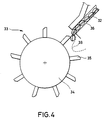
- the separating device is assigned a briquette strand divider 33 which, as can be seen in particular in FIG. 4, comprises a rotor 34 which has rotor blades 35 which protrude radially on its outer casing.
- the peripheral speed of the rotor 34 is adjusted according to the speed of the roller press 8, so that a briquette with a rotor blade 35 is knocked off.
- the briquette strand is guided on a guide rail 36, over the free end of which a hold-down 37 is provided for depressing the briquette strand 32 that bulges out during the knock-off process. Since, as can be seen from FIG.
- the briquette strand 32 is also formed from two adjacent briquettes 17, a nose 38 is also provided, which is shown in broken lines in FIG. 4.
- the nose 38 then cuts through the central web of the briquette strand 32.
- the rotor 34 is preferably shaped accordingly.
- roller press 8 Above the roller press 8 and below the briquette strand divider 33, the system and its mode of operation is the same as that described above.
- the method according to the invention thus also provides the possibility that fine ore can be processed independently of the control concept of the roller press 8. This is particularly the case with the control concept described last positively noticeable in that the service life of the molds with the briquette troughs 11 can be increased significantly. This can also significantly reduce the segment or ring costs in hot briquetting systems for fine ore.
Abstract
Description
Die Erfindung bezieht sich auf ein Verfahren zum Herstellen von Eisenschwammbriketts aus Feinerz, mit einer maximalen Korngröße von kleiner als 2 mm, bevorzugt kleiner als 0,5 mm, bei dem einer Walzenpresse heißes Feinerz zugeführt und von sich gegenüberliegenden Brikettmulden der Walzenpresse zu Eisenschwammbriketts brikettiert wird und beim Brikettiervorgang zwischen den die Brikettmulden voneinander trennenden Stegen kompaktiertes Feinerz und staubförmiger Abrieb entsteht, die als Rückgut von den Eisenschwammbriketts getrennt werden und dem Feinerz vor dem Brikettiervorgang zugeführt werden, wobei die mittlere Körnung des Feinerzes kleiner ist, als die mittlere Teilchengröße des Rückgutes.The invention relates to a method for producing sponge iron briquettes from fine ore, with a maximum grain size of less than 2 mm, preferably less than 0.5 mm, in which hot fine ore is fed to a roller press and briquetted from opposing briquette troughs of the roller press to form sponge iron briquettes and during the briquetting process, compacted ore and dust-like abrasion occur between the webs separating the briquette troughs, which are separated as return material from the sponge iron briquettes and are fed to the fine ore before the briquetting process, the average grain size of the fine ore being smaller than the average particle size of the returned material.
Üblicherweise hat sich Stand der Technik durchgesetzt, Feinerz vor dem Heißbrikettieren zu Pellets zu formen. Beim Brikettiervorgang entstehen dann Eisenschwammbriketts und Rückgut, wobei das Rückgut den Pellets oberhalb der Walzenpresse wieder zugeführt wird.The prior art has usually established itself to form fine ore into pellets before hot briquetting. The briquetting process then produces spongy iron briquettes and return material, the return material being fed back to the pellets above the roller press.
Darüber hinaus ist im Stand der Technik eine einzige Anlage bekannt geworden, bei der Feinerz in seiner anfallenden feinteiligen Form direkt verpreßt wird. Bei diesem Verfahren wird das Rückgut gesammelt und dann dem Feinerz vor dem Brikettiervorgang zugeführt. Dieses Verfahren hat sich aber in der Praxis nicht allzusehr bewährt und konnte sich nicht durchsetzen.In addition, a single system has become known in the prior art, in which fine ore is pressed directly in its resulting fine-particle form. In this process, the return material is collected and then fed to the fine ore before the briquetting process. However, this method has not proven itself too well in practice and has not been able to establish itself.
Es ist daher die Aufgabe der vorliegenden Erfindung, ein Verfahren zum Herstellen von Eisenschwammbriketts aus feinteiligem Feinerz so zu verbessern, daß der Brikettiervorgang im wesentlichen störungsfrei ablaufen kann.It is therefore the object of the present invention to improve a method for producing sponge iron briquettes from finely divided fine ore in such a way that the briquetting process can proceed essentially without interference.
Diese Aufgabe wird erfindungsgemäß dadurch gelöst, daß das Rückgut nach dem Trennen von den Eisenschwammbriketts direkt einem Fördersystem zugeführt wird und das noch heiße Rückgut von dem Fördersystem im wesentlichen gleichmäßig und kontinuierlich dem heißen noch zu brikettierenden Feinerz zugeführt wird.This object is achieved in that the return material directly after separation from the sponge iron briquettes is fed to a conveyor system and the still hot return material is fed from the conveyor system substantially uniformly and continuously to the hot ore still to be briquetted.
Zwar ist ein kontinuierliches Zuführen des Rückgutes beim Brikettieren von Pettets und/oder Stückerz bekannt. Jedoch handelt es sich hierbei um eine reine Recyclingmaßnahme, die keinen Einfluß auf die Verarbeitung des pelletierten Feinerzes aufweist, siehe z.b. US-A-3 627 288.A continuous feeding of the return material when briquetting pettets and / or lump ore is known. However, this is a pure recycling measure that has no influence on the processing of the pelletized fine ore, see e.g. US-A-3 627 288.
Die Erfindung bietet demgegenüber bei der Verarbeitung von feinteiligen Feinerzen den Vorteil, daß der in das Feinerz zugeführte Rückgutstrom im wesentlichen eine gleichmäßige Temperatur und einen gleichmäßigen Mengenanteil bereitstellt. Das Feinerz wird dann durch das kontinuierlich zugeführte Rückgut gleichmäßig vergröbert, was der besseren Brikettierbarkeit zugute kommt. Der üblicherweise für notwendig erachtete Schritt des Pelletierens bevor das Feinerz verarbeitet werden konnte, kann durch die vorliegende Erfindung komplett entfallen, da durch die ununterbrochene Zufuhr von Rückgut Einfluß auf das Verhalten des Feinerzes genommen werden kann. Zudem kann das Rückgut mit jeweils einer in einem bestimmten Temperaturbereich wählbaren Temperatur zurückgeführt werden, die von der Geschwindigkeit des Transportsystems abhängt. Hierdurch werden insbesondere auch thermische Schwankungen innerhalb des zu verarbeitenden Materials vermieden, die zu einer übergroßen Belastung der Walzenpressen führen können. Durch die Erfindung werden somit die Standzeiten der Walzenpresse merklich erhöht, was letztendlich geringere Kosten verursacht.In contrast, when processing fine-particle fine ores, the invention offers the advantage that the return material stream fed into the fine ore essentially provides a uniform temperature and a uniform proportion of the quantity. The fine ore is then coarsened evenly by the continuously fed return material, which benefits the better briquetting. The step of pelleting, which is usually considered necessary before the fine ore could be processed, can be completely eliminated by the present invention, since the behavior of the fine ore can be influenced by the continuous supply of return material. In addition, the returned goods can each be returned at a temperature which can be selected in a specific temperature range and which depends on the speed of the transport system. As a result, thermal fluctuations within the material to be processed, which can lead to excessive loading of the roller presses, are avoided in particular. The service life of the roller press is thus noticeably increased by the invention, which ultimately results in lower costs.
Vorteilhaft ist es weiterhin, wenn die Eisenschwammbriketts und das Rückgut nach dem Brikettieren in eine Vibrationstrommel oder eine Rotationstrommel fallen, um Rückgut und Eisenschwammbriketts im wesentlichen vollständig voneinander zu lösen. Eine solche Verfahrensweise ist insbesondere dann von Vorteil, wenn die Eisenschwammbriketts mit starren Brikettwalzen verpreßt werden, die eine relativ dünne Brikettnaht zulassen, wodurch sich die Briketts und das Rückgut durch eine relativ simple Vibrationstrommel oder Rotationstrommel voneinander lösen lassen. Weiterhin ist es dann günstig, wenn die Eisenschwammbriketts und das Rückgut von der Vibrationstrommel oder Rotationstrommel auf ein Vibrationssieb gefördert werden, das Eisenschwammbriketts und Rückgut voneinander trennt. Nachdem die Eisenschwammbriketts und das Rückgut von der Vibrationstrommel oder Rotationstrommel voneinander gelöst sind, ist es durch ein einfaches Vibrationssieb relativ einfach diese beiden Bestandteile voneinander zu trennen.It is furthermore advantageous if the sponge iron briquettes and the return material fall into a vibration drum or a rotary drum after briquetting in order to essentially completely separate the return material and sponge iron briquettes from one another. Such a procedure is particularly then of advantage if the sponge iron briquettes are pressed with rigid briquette rollers, which allow a relatively thin briquette seam, as a result of which the briquettes and the returned material can be separated from one another by a relatively simple vibration drum or rotary drum. Furthermore, it is then advantageous if the sponge iron briquettes and the return material are conveyed from the vibratory drum or rotary drum onto a vibrating screen which separates the sponge iron briquettes and return material. After the iron sponge briquettes and the return material are detached from one another by the vibration drum or rotary drum, it is relatively simple to separate these two components from one another by means of a simple vibration sieve.
Besonders verfahrensgünstig läßt sich das Feinerz mit der Walzenpresse verarbeiten, wenn das Feinerz und Rückgut einem oberhalb der Brikettierwalzen angeordneten Schneckenbunker zugeführt werden, dessen Schnecke das vermischte Feinerz und Rückgut in den Walzenspalt der Brikettierwalzen preßt. Dieser Verfahrensschritt hat zum einen den Vorteil, daß sich durch das Vorpressen mit der Schnecke das Mischgut nochmal erhitzt, wodurch Temperaturschwankungen zwischen Rückgut und Feinerz im wesentlichen ausgeglichen werden können und zum anderen ermöglicht ein solcher Schneckenbunker durch die Bewegung von dem Mischgut, daß sich das Feinerz beruhigt und entgasen kann. Das ist insofern wichtig, da das Feinerz durch seinen Transport eine starke Auflockerung bis hin zur Fluidisierung erfährt. Kontinuierlich zugeführtes und relativ heißes Rückgut trägt seinen Teil dazu bei, daß sich das Feinerz beruhigt.The fine ore can be processed in a particularly advantageous manner with the roller press if the fine ore and return material are fed to a screw hopper arranged above the briquetting rollers, the screw of which presses the mixed fine ore and return material into the roller gap of the briquetting rollers. This process step has the advantage, on the one hand, that the mixed material is heated again by the pre-pressing with the screw, whereby temperature fluctuations between the returned material and fine ore can essentially be compensated for and, on the other hand, such a screw bunker enables the fine ore to move by moving the mixed material calms and can degas. This is important because the fine ore experiences a strong loosening up to fluidization through its transport. Continuously fed and relatively hot return material does its part to calm the fine ore.
In einem weiteren Verfahrensschritt können dann die heißen Eisenschwammbriketts nach dem Trennen vom Rückgut einem Brikettkühler zugeführt werden. Um ein möglichst schnelles Abkühlen der Eisenschwammbriketts zu erlangen, können diese in einem Wasserbad im Brikettkühler abgekühlt werden. Es hat sich gezeigt, daß die Reoxidation, die durch das Abkühlen, verhindert werden soll, durch das Abkühlen in einem Wasserbad nicht wesentlich von einem Abkühlen an Luft unterscheidet.In a further process step, the hot sponge iron briquettes can then be fed to a briquette cooler after separation from the returned material. In order to cool the sponge briquettes as quickly as possible, they can be cooled in a water bath in the briquette cooler. It has been shown that the reoxidation caused by cooling, should be prevented by cooling in a water bath does not differ significantly from cooling in air.
Das von dem Sieb abgetrennte Rückgut weist bevorzugt eine maximale Korngröße von ca. 15 mm auf. Dieser Grenzwert garantiert, daß zu grobes Rückgut keinen störenden Einfluß auf den Brikettiervorgang hat.The return material separated from the sieve preferably has a maximum grain size of approximately 15 mm. This limit value guarantees that excessively coarse return material has no disruptive influence on the briquetting process.
In einer weiteren Verfahrensform kann das Feinerz und Rückgut derart von der Walzenpresse verpreßt werden, daß zumindest Eisenschwammbrikettstrangstücke entstehen. Das Verpressen von Eisenschwamm zu Brikettsträngen ist allgemein nur bei der Verarbeitung von Stückerz und/oder Pellets bekannt. Hierzu verfügt die Walzenpresse über eine Los- und eine Festwalze, damit sich der Walzenspalt der zugeführten Materialmenge anpassen kann. Durch die große Fließfähigkeit des Feinerzes ist es durch die vorgeschlagene Erfindung erstmals möglich, daß durch das kontinuierlich zugeführte, heiße Rückgut das Feinerz auch für die Verpressung als Brikettstrang handhabbar gemacht worden ist. Dies hat weiterhin den Vorteil, daß eine solche Verpressungsart eine höhere Standzeit der Walzenpressen garantiert. Bevorzugt wird dann der Brikettstrang von einem Brikettstrangzerteiler in einzelne Eisenschwammbriketts und Rückgut zerteilt. Anschließend fallen die Eisenschwammbriketts und das Rückgut auf das Vibrationssieb.In a further form of the process, the fine ore and return material can be pressed by the roller press in such a way that at least pieces of iron sponge briquette are produced. The pressing of sponge iron into briquette strands is generally only known when processing piece ore and / or pellets. For this purpose, the roller press has a loose and a fixed roller so that the roller gap can adapt to the amount of material fed. Because of the great flowability of the fine ore, the proposed invention makes it possible for the first time that the fine ore can also be handled as a briquette strand by the continuously supplied, hot return material. This has the further advantage that such a type of pressing guarantees a longer service life of the roller presses. The briquette strand is then preferably divided by a briquette strand divider into individual sponge iron briquettes and return material. The iron sponge briquettes and the return material then fall onto the vibrating sieve.
Günstige Voraussetzungen zum Brikettieren des Feinerzes werden dadurch geschaffen, daß das Feinerz vor dem Brikettieren eine Temperatur von im wesentlichen 650 bis 830°C aufweist. Darüber hinaus ist es weiterhin von Vorteil, wenn das Rückgut beim Zuführen in das Feinerz eine Temperatur von im wesentlichen oberhalb 300°C aufweist. Eine solche Temperatur ist innerhalb einer Heißbrikettieranlage mit einem Stetigförderer ohne weiters einhaltbar.Favorable conditions for briquetting the fine ore are created in that the fine ore has a temperature of substantially 650 to 830 ° C. before the briquetting. In addition, it is also advantageous if the return material has a temperature of substantially above 300 ° C. when it is fed into the fine ore. Such a temperature can easily be maintained within a hot briquetting system with a continuous conveyor.
Um eine vorzeitige Reoxidation des Eisenschwamms bzw. der Eisenschwammbriketts zu verhindern, werden zumindest der Brikettiervorgang, die Rückguttrennung und die Rückgutförderung im wesentlichen unter einer Inertgasatmosphäre durchgeführt.In order to prevent premature reoxidation of the sponge iron or the sponge iron briquettes, at least the briquetting process, the separation of returned material and the return material conveyance are carried out essentially under an inert gas atmosphere.
Weiterhin wird Schutz für eine Heißbrikettieranlage zum Herstellen von Eisenschwammbriketts aus Feinerz, insbesondere nach einem Verfahren gemäß einem der Ansprüche 1 bis 12, begehrt. Die Heißbrikettieranlage weist eine Walzenpresse, die ein mit Formmulden versehenes Walzenpaar umfaßt, eine unterhalb der Walzenpresse angeordnete Trennvorrichtung zum Trennen von Eisenschwammbriketts und Rückgut und ein Fördersystem zum Fördern des Rückgutes von der Trennvorrichtung zu einem oberhalb der Walzenpresse angeordneten Bunker, in dem das Rückgut mit dem heißen Feinerz vermischt wird, auf. Die Heißbrikettieranlage zeichnet sich dadurch aus, daß das Fördersystem einen Stetigförderer zum im wesentlichen kontinuierlichen und gleichmäßigen Rückführen des Rückgutes im wesentlichen heißen Zustand umfaßt.Protection for a hot briquetting system for producing sponge iron briquettes from fine ore, in particular by a method according to one of
Eine solche Anlage zur Verarbeitung von Feinerz ist im Stand der Technik nicht bekannt und bietet die bereits obenerwähnten Vorteile.Such a plant for processing fine ore is not known in the prior art and offers the advantages mentioned above.
Bevorzugt ist an dem Bunker ein nach oben gerichtetes Fallrohr zum Zuführen des Rückgutes angeordnet, dessen oberes Ende einem das Rückgut aufwärts fördernden in das obere Ende entleerenden Stetigförderer, bevorzugt ein Becherwerk, zugeordnet ist. Eine solche Ausgestaltung ermöglicht einen relativ schnellen und konstruktiv einfachen Transportmechanismus für das Rückgut.An upward-directed downpipe for feeding the return material is preferably arranged on the bunker, the upper end of which is assigned to a continuous conveyor, preferably a bucket elevator, which conveys the upward material and empties it into the upper end. Such a configuration enables a relatively quick and structurally simple transport mechanism for the returned goods.
Günstig ist es weiterhin, wenn der Bunker ein Schneckenbunker ist, dessen Vorpreßschnecke im wesentlichen am unteren Ende des Schneckenbunkers und oberhalb des Walzenspaltes des Walzenpaares zum Einpressen von vermischtem Feinerz und Rückgut in den Walzenspalt angeordnet ist. Solche Schneckenbunker haben sich bereits zum Zuführen von feinteiligem Ausgangsmaterial in einen Walzenspalt bewährt.It is also advantageous if the bunker is a screw bunker, the pre-press screw of which is essentially at the lower end of the screw bunker and above the roller gap of the pair of rollers for pressing in mixed fine ore and Rear goods are arranged in the nip. Such screw bunkers have already proven themselves for feeding finely divided starting material into a roll nip.
In einer bevorzugten Ausführungsform, weist das Walzenpaar eine Loswalze und eine Festwalze auf, wobei sich die Loswalze entsprechend der zugeführten Materialmenge anpaßt und die Dicke der Brikettnaht zum bevorzugten Erzeugen eines Brikettstrangs einstellbar ist. Eine solche Regulierung der Walzenpresse ist bei der Verarbeitung von Feinerz bislang nicht bekannt. Sie bietet jedoch den großen Vorteil, daß die Walzenpresse eine nennenswert höhere Standzeit aufweist. Günstigerweise ist hierbei unterhalb des Walzenpaares ein Brikettstrangzerteiler als Bestandteil der Trennvorrichtung angeordnet, der den Brikettstrang in einzelne Briketts und Rückgut zerteilt.In a preferred embodiment, the pair of rollers has a loose roller and a fixed roller, the loose roller adapting itself in accordance with the amount of material supplied and the thickness of the briquette seam being adjustable for the preferred production of a briquette strand. Such regulation of the roller press is not yet known when processing fine ore. However, it has the great advantage that the roller press has a significantly longer service life. Conveniently, a briquette strand divider is arranged below the pair of rollers as part of the separating device, which divides the briquette strand into individual briquettes and return material.
In einer anderen Ausführungsform weist das Walzenpaar zwei starre Festwalzen zum Herstellen von Briketts mit einer Brikettnaht von relativ kleiner Dicke auf. Diese Regelungsart der Walzenpresse hat sich bei feinteiligem Ausgangsmaterial recht gut bewährt. Die Briketts werden im wesentlichen einzeln oder als Brikettstrangstücke, deren Briketts aber sehr leicht voneinander zu trennen sind, von der Walzenpresse ausgetragen. Die Briketts weisen bei dieser Regelungsart eine besonders gleichmäßige Form auf. Günstigerweise ist dann unterhalb der Walzenpresse eine Vibrationstrommel oder Rotationstrommel als Bestandteil der Trennvorrichtung zum Lösen von Briketts und Rückgut voneinander angeordnet, in die die Briketts und das Rückgut nach dem Brikettiervorgang hineinfallen. Die Vibrationstrommel oder Rotationstrommel ist vollkommen ausreichend um die Briketts zu vereinzeln und Briketts und Rückgut voneinander zu lösen.In another embodiment, the pair of rollers has two rigid rollers for producing briquettes with a briquette seam of relatively small thickness. This type of control of the roller press has proven itself quite well with finely divided starting material. The briquettes are essentially discharged from the roller press individually or as briquette strand pieces, the briquettes of which are very easy to separate from one another. With this type of regulation, the briquettes have a particularly uniform shape. A vibration drum or rotary drum is then advantageously arranged below the roller press as a component of the separating device for releasing briquettes and return material into which the briquettes and the return material fall after the briquetting process. The vibratory drum or rotary drum is completely sufficient to separate the briquettes and to separate the briquettes and the returned goods.
Die Vibrationstrommel oder Rotationstrommel kann weiterhin als Fördermittel benutzt werden, wenn die Achse der Vibrationstrommel oder Rotationstrommel eine geringe Neigung gegenüber der Waagerechten aufweist. Die Briketts und das Rückgut werden dann in Neigungsrichtung gefördert.The vibratory drum or rotary drum can continue to be used as a conveyor if the axis of the vibratory drum or rotary drum is slightly inclined towards the horizontal. The briquettes and the returned goods are then conveyed in the direction of inclination.
Der Trennvorrichtung kann weiterhin ein Sieb zum Trennen von Briketts und dem Rückgut zugeordnet sein, wobei das Sieb bevorzugt eine Maschenweite von 8 bis 15 mm aufweist. Durch die Maschenweite des Siebes kann durch diese Anordnung entschieden werden, wo die Grenze zwischen Rückgut und Brikett zu ziehen ist.The separating device can also be assigned a sieve for separating briquettes and the return material, the sieve preferably having a mesh size of 8 to 15 mm. Due to the mesh size of the sieve, this arrangement can be used to decide where to draw the line between the returned goods and the briquette.
Das Sieb kann ebenfalls als Fördermittel verwendet werden, wenn das Sieb als leicht geneigtes Vibrationssieb ausgebildet ist, das die Eisenschwammbriketts in einen sich von einem Austragsende des Siebes nach unten erstreckenden Brikettschacht fördert. Durch die Rüttelbewegung des Vibrationssiebs wird gleichzeitig sichergestellt, daß sich Briketts und Rückgut im wesentlichen vollständig voneinander trennen.The sieve can also be used as a conveying means if the sieve is designed as a slightly inclined vibrating sieve which conveys the sponge iron briquettes into a briquette shaft which extends downward from a discharge end of the sieve. The shaking movement of the vibrating sieve also ensures that the briquettes and the returned goods are essentially completely separated from one another.
Weiterhin kann unterhalb des Siebes eine Vibrationsfläche zur Aufnahme und zum direkten Weitertransportieren des Rückgutes angeordnet sein, wobei die Vibrationsfläche das Rückgut in einen sich von einem Austragsende der Vibrationsfläche nach unten erstreckenden Rückgutschacht fördert, der an seinem unteren Ende einem unteren Bereich des Stetigförderers zur Abgabe des Rückgutes zugeordnet ist. Das Rückgut gelangt somit auf schnellstem Wege von dem Sieb zum Stetigförderer. Durch das schnelle Weiterleiten des Rückgutes wird ein übermäßig großer Wärmeverlust verhindert. Günstigerweise mündet das untere Ende des Brikettschachts in einen Brikettkühler. Der Brikettkühler sorgt für die nötige Abkühlung der Briketts, damit diese nicht unvorteilhafterweise zu sehr reoxidieren. Besonders vorteilhaft kann hierbei sein, wenn der Brikettkühler als mit einem Wasserbad kühlender Vibrationskühler ausgebildet ist, der einen Wasserzufluß und -abfluß, sowie eine Austragsstelle für die Briketts aufweist. Durch das Wasserbad wird einerseits eine schnelle Abkühlung der Eisenschwammbriketts erreicht und werden zum anderen gleichzeitig von dem Vibrationskühler zum Weitertransport ausgetragen.Furthermore, a vibrating surface can be arranged below the sieve for receiving and for direct transport of the returned goods, the vibrating surface conveying the returned goods into a return goods shaft which extends downward from a discharge end of the vibrating surface and at its lower end a lower area of the continuous conveyor for delivering the Return goods is assigned. The return material thus reaches the continuous conveyor from the sieve as quickly as possible. Excessive heat loss is prevented by the rapid forwarding of the returned goods. The lower end of the briquette shaft favorably opens into a briquette cooler. The briquette cooler ensures that the briquettes cool down so that they do not disadvantageously reoxidize too much. It can be particularly advantageous here if the briquette cooler is designed as a vibration cooler that cools with a water bath and has a water inflow and outflow and a discharge point for the briquettes. The water bath quickly cools down the iron sponge briquettes on the one hand and on the other discharged from the vibration cooler for further transport at the same time.
Bevorzugt ist hierbei dem Brikettkühler ein mit dem Wasserzufluß und -abfluß verbundener Wärmetauscher zum Rückkühlen des Kühlwassers zugeordnet. Durch dieses Kühlsystem können erhebliche Mengen Kühlwasser eingespart werden, was insbesondere in Ländern mit Wasserknappheit von extremer Bedeutung ist.In this case, the briquette cooler is preferably associated with a heat exchanger connected to the water inflow and outflow for cooling the cooling water back. This cooling system can save considerable amounts of cooling water, which is extremely important, especially in countries with water shortages.
Um die Reoxidation der Eisenschwammbriketts auch während des Verarbeitungsvorganges weitgehend zu verhindern, sind die Walzenpresse, die Trennvorrichtung, der Brikettkühler und das Fördersystem von einem gasdichten Gehäuse umgeben, das einen Gasanschluß zum Einleiten von bevorzugt Inertgasen aufweist. Auch der Bunker kann einen Anschluß zum Einleiten von Inertgasen, sowie ein Entlüftungsventil aufweisen. Das Entlüftungsventil dient hierbei zum Ableiten von in den Feinerzporen gelagerten Gaseinschlüssen.In order to largely prevent reoxidation of the sponge iron briquettes even during the processing operation, the roller press, the separating device, the briquette cooler and the conveyor system are surrounded by a gas-tight housing which has a gas connection for introducing preferably inert gases. The bunker can also have a connection for introducing inert gases, as well as a vent valve. The vent valve is used to discharge gas inclusions stored in the fine ore pores.
Im folgenden werden Ausführungsbeispiele der vorliegenden Erfindung anhand einer Zeichnung näher erläutert. Es zeigt:
- Fig. 1
- ein erstes Ausführungsbeispiel der vorliegenden Erfindung in einer schematischen Darstellung,
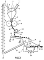
- Fig. 2
- eine zweite Ausführungsform der vorliegenden Erfindung in einer schematischen Darstellung,
- Fig. 3
- ein Walzenpaar einer Brikettwalzenpresse in einer schematischen Draufsicht und
- Fig. 4
- ein Brikettstrangzerteiler in einer schematischen Darstellung.
- Fig. 1
- a first embodiment of the present invention in a schematic representation,
- Fig. 2
- 2 shows a second embodiment of the present invention in a schematic illustration,
- Fig. 3
- a pair of rollers of a briquette roller press in a schematic plan view and
- Fig. 4
- a briquette strand divider in a schematic representation.
Insbesondere anhand der Fig. 1 wird im folgenden eine erste Ausführungsform des erfindungsgemäßen Verfahrens und eine Ausführungsform einer Vorrichtung zur Durchführung dieses Verfahrens erläutert. Als Ausgangsprodukt für das vorliegende Verfahren dient feinteiliger Eisenschwamm 1, der in der Wirbelschicht verarbeitet wurde und in reduzierter Form im heißen Zustand der Heißbrikettieranlage zugeführt wird. Die Korngröße des Feinerzes 1 beträgt hierbei maximal 2 mm, wobei jedoch der größte Teil eine Größe von kleiner als 0,5 mm aufweist. Die Temperatur des Feinerzes 1 beträgt hierbei im wesentlichen zwischen 650 und 830°C. Das Feinerz 1 hat dabei ein Schüttgewicht von ca. 2,3 g/cm3 und wird der Heißbrikettieranlage über einen Zuführstutzen 2, der an einem oberen Endbereich eines Schneckenbunkers 3 angeordnet ist, eingeleitet. Das Feinerz 1 ist durch den Transport sehr stark aufgelockert, wodurch es sogar zur Fluidisierung kommen kann. Aus diesem Grunde ist der Schneckenbunker 3 nicht vollständig mit Schüttgut gefüllt, damit Gaseinschlüsse im Feinerz 1 nach oben entweichen und über ein Entlüfungsventil 4 abgegeben werden können. Des weiteren ist an dem oberen Endbereich des Schneckenbunkers 3 ein Fallrohr 5 zum Zuführen von Rückgut 6 in den Schneckenbunker 3 vorgesehen. Das Rückgut 6 setzt sich zusammen aus kompaktierten Feinerz 1, das eine Korngröße von kleiner als 15 mm, bevorzugt kleiner als 0,5 mm, aufweist.1, a first embodiment of the method according to the invention and a Embodiment of an apparatus for performing this method explained. The starting product for the present process is finely divided
In dem Schneckenbunker 3 ist weiterhin eine Vorpreßschnecke 7 angeordnet, die vermischtes Rückgut 6 und Feinerz 1 in den Walzenspalt einer Walzenpresse 8 hineindrückt. Der Antrieb der Schneckenwelle erfolgt über einen nichtdargestellten Hydraulikantrieb, der über ein im Falle des Klemmens der Schnecke 7 hohes Drehmoment verfügt und in der Lage ist, sich allen Schwankungen elastisch anzupassen. Der Schneckenbunker 3 ist aus hochhitzebeständigen Stahl gefertigt und mit einer nichtdargestellten Isolierung gegen Wärmeabstrahlung umgeben. Die Walzenpresse 8 verfügt über eine erste Preßwalze 9 und eine zweite Preßwalze 10.In the
Wie insbesondere in Fig. 3 zu erkennen ist, sind die Walzen mit Brikettmulden 11 versehenen Formzeugen aus Segmenten oder mit Ringen ausgerüstet. Ein Walzenkörper 12, auf den die Formzeuge aufgesetzt sind, ist in, bevorzugt Pendelrollenlagern 13 gelagert und mit einer entsprechenden nichtdargestellten Kühlung versehen. Die Preßwalze 8 ist bei dieser Ausführungsform als starre Walze ausgeführt, wodurch Lagergehäuse 14 unbeweglich angeordnet sind. Die zweite Preßwalze 10 hingegen, weist verschiebbare Lagergehäuse 15 auf, wodurch sich der Walzenspalt zwischen der ersten und zweiten Preßwalze 9 und 10 einstellen läßt. Der nötige Verstellweg und nötige Anpreßdruck der beiden Preßwalzen 9 und 10 wird durch Hydraulikzylinder 16 erreicht, die an dem verschiebbaren Lagergehäuse 15 angreifen.As can be seen in particular in FIG. 3, the rollers are equipped with
Bei dem in Fig. 1 gezeigten Ausführungsbeispiel ist der Druck in den Hydraulikzylindern 16 jedoch so eingestellt, daß die Preßwalze 10 ebenfalls zu einer Festwalze wird. In einem solchen Fall geht der Hydraulikdruck über die Lagergehäuse 14 und 15 auf nichtdargestellte Distanzstücke. In den Distanzstücken zwischen Lagerblöcken liegen Druckmeßdosen. Diese messen zunächst den vollen Druck ohne Material. Durch Einführen von vermischtem Feinerz 1 und Rückgut 6 werden nun die Druckmeßdosen teilweise entlastet. Diese Signalveränderung kann dann zur Regelung der Schneckendrehzahl herangezogen werden.In the embodiment shown in Fig. 1, however, the pressure in the
Eine solche Steuerung hat den Vorteil, daß Material von der Walzenpresse 8 zu Eisenschwammbriketts 17 verpreßt wird, die eine relativ geringe Brikettnahtdicke aufweisen, wodurch die Briketts 17 im wesentlichen direkt nach dem Brikettiervorgang schon vereinzelt sind, oder sich durch diese geringe Brikettnahtdicke relativ einfach vereinzeln lassen. Wie in Fig. 1 zu sehen ist, fallen die Briketts 17 oder Brikettstrangstücke in eine trichterförmige Einführung einer Vibrationstrommel 18 oder Rotationstrommel, die sich je nach Ausführung um ihre eigene Achse drehen kann und eine Rüttelbewegung ausführt. Da die Walzen 9 und 10 der Walzenpresse 8 immer einen gewissen Walzenspalt aufweisen, wird auch durch die Stegbereiche zwischen den Brikettmulden 11 Material verpreßt, das dann als Bruchstücke aus der Walzenpresse 8 ausgetragen und ebenfalls in die Vibrationstrommel 18 oder Rotationstrommel eingebracht wird. Diese kompaktierten Feinerzbruchstücke und eventueller Feinerzabrieb werden als Rückgut 6 bezeichnet, weil sie später dem Verfahren wieder zugeführt werden.Such a control has the advantage that material is pressed by the
Durch die Vibrationstrommel 18 oder Rotationstrommel werden nunmehr das Rückgut 6 und die Briketts 17 im wesentlichen vollständig voneinander gelöst. Durch die eventuell gleichzeitige Rotationsbewegung wird auch ein leichter Mahlvorgang ausgeführt, wodurch das Rückgut teilweise verkleinert wird. Die Vibrationstrommel 18 oder Rotationstrommel weist eine geringe Neigung gegenüber der Waagerechten auf, so daß das Rückgut 6 und die Briketts 17 in Neigungsrichtung weitergefördert werden.The
Am Ende der Vibrationstrommel 18 oder Rotationstrommel fallen dann das Rückgut 6 und die Briketts 17 auf ein Vibrationssieb 19, das bevorzugt eine Maschenweite von 8 bis 15 mm aufweist. Durch die Rüttelbewegung des Vibrationssiebs 19 das ebenfalls leicht geneigt ist, fallen sämtliche Rückgutstücke, die eine gewisse Größe unterschreiten, durch das Sieb 19 hindurch und gelangen auf eine unterhalb des Siebes 19 im wesentlichen parallel dazu angeordnete Vibrationsfläche 20. Wird das Vibrationssieb 19 lang genug gewählt, ist nach einer bestimmten Wegstrecke das gesamte Rückgut unterhalb einer bestimmten Größe von den Briketts 17 getrennt. Die Vibrationsfläche 20 weist ein Austragsende 21 auf, unterhalb dessen sich ein nach unten erstreckender Rückgutschacht 22 befindet. Der Rückgutschacht 22 nimmt das Rückgut 6 auf und leitet es weiter zu einem unteren Bereich eines Stetigförderers 23, der das Rückgut 6 sofort aufnimmt und nach oben fördert. Der Stetigförderer 23 ist bevorzugt als Becherwerk ausgebildet. An seinem oberen Ende gibt der Stetigförderer 23 das Rückgut 6 an das Förderrohr 5 ab, wodurch dieses wieder in den Schneckenbunker 3 gelangt. Je nach Dauer des Betriebes des Rückführsystems ist der Temperaturverlust des Rückgutes 6 relativ gering. Der gesamte Rückführzeitraum vom Sieb 19 zur Schnecke 7 beträgt ca. nur 30 Sekunden. Das bedeutet, daß die vorhandene Temperatur des Rückgutes 6 beim Einfüllen in den Schneckenbunker immerhin noch mindestens 300°C beträgt.At the end of the
Sämtliche kompaktierten Teile oberhalb der Maschengröße des Vibrationssiebes 19 werden nun durch das leicht geneigte Vibrationssieb 19 weitertransportiert, bis sie in einen Brikettschacht 24 eingefüllt werden. Der Brikettschacht 24 mündet in einen Brikettkühler 25 der als ein mit einem Wasserbad 26 kühlender Vibrationskühler ausgebildet ist. Das Wasserbad 26 sorgt für eine schnelle Abkühlung der Briketts 17 und verhindert gleichzeitig deren Reoxidation im warmen Zustand. An dem Brikettkühler 25 sind ein Wasserzulauf 27 zur Zufuhr von Frischwasser für das Wasserbad 26 und ein Wasserablauf 28 zum Abführen aus dem erwärmten Wasserbad 26 angeordnet. Das Kühlwasser wird in einem Kühlkreislauf von dem Wasserablauf 28 über einen Wärmetauscher 29 zum Wasserzulauf 27 transportiert und innerhalb des Brikettkühlers 25 im Gegenstrom zur Transportrichtung der Briketts 17 durch den Kühler 25 geleitet. Die Briketts 17 werden von ca. 700°C auf ca. 80°C abgekühlt. Durch Regelung der Wasserumlaufmenge und Verweilzeit der Briketts 17 im Wasserbad 26 kann die Austragstemperatur der Briketts 17 variiert werden. Wenn die Briketts 17 mit ca. 80°C an einer Austragsstelle 30 des Brikettkühlers 25 ausgetragen werden, reicht die Restwärme der Briketts 17 dazu aus, die Oberfläche der Briketts 17 abzutrocknen. Der Vibrationskühler 25 ist bevorzugt mit einem regelbaren Antrieb ausgerüstet, der die Einstellung der Verweilzeit der Briketts 17 ermöglicht. Die Briketts 17 gelangen dann von der Austagsstelle 30 auf ein Brikettförderband 31.All compacted parts above the mesh size of the vibrating
Eisenschwamm weist eine große Neigung zur Reoxidation auf, insbesondere dann, wenn dessen Temperatur noch relativ hoch ist. Beim Brikettieren passiert auch ein gewisser Feingutanteil unverpreßt die Walzenpresse 8. Dadurch müssen alle Räume um die Walzenpresse 8, die Trennvorrichtung, sowie der Raum um den Stetigförderer 23 unbedingt sauerstoffarm gehalten werden. Hierzu wird bevorzugterweise mit Inertgas gespült bzw. eine Inertgasatmosphäre hergestellt. Die einzelnen Aggregate sind mit entsprechenden Anschlüssen für Inertgas ausgerüstet. Auch der Schneckenbunker 3 und der Brikettkühler 25 können jeweils einen Anschluß für Inertgas aufweisen. Hierzu weisen die Aggregate im wesentlichen nichtdargestellte gasdichte Gehäuse auf. Durch das Bereitstellen einer heißen Inertgasatmosphäre läßt sich der Temperaturverlust des Rückgutes 6 nochmals reduzieren.Sponge iron has a great tendency to reoxidize, especially when its temperature is still relatively high. When briquetting, a certain proportion of fine material passes unpressed the
Das relativ feine Ausgangsgut findet insbesondere auch Berücksichtigung bei den Walzendurchmessern und bei der Umfangsgeschwindigkeit, mit der die Preßwalzen 9 und 10 brikettieren können. Wegen des schlechten Einzugs des Feinerzes 1 hat sich ein Walzendurchmesser von ca. 1400 mm als günstig erwiesen. Die Umfangsgeschwindigkeit beträgt dabei maximal 0,36 m/s, was einer Drehzahl von 5 Umdrehungen/min entspricht. Soll nun Feinerz 1 mit einer besonders kleinen Körnungsgröße verarbeitet werden, ergibt sich die Notwendigkeit, die Walzendrehzahl erheblich zu reduzieren. Deshalb wird bei solchen Anlagen die Drehzahl nicht nur nach der gewünschten Austragsmenge, sondern auch nach der Brikettierbarkeit des Feinerzes 1 geregelt. Das bedeutet, daß je feiner das Ausgangsprodukt ist, um so langsamer müssen die Preßwalzen 1 und 10 rotieren. Das bedeutet aber auch, daß bei optimaler Körnung eine Steigerung der Durchsatzleistung der Walzenpresse durch Erhöhung der Umfangsgeschwindigkeiten zu erwarten ist. Eine solche optimale Körnung kann aber auch erreicht werden, indem ein entsprechender Anteil an Rückgut 6 dem an sich zu feinen Feinerz 1 beigemischt wird. Hier zeigt sich, welch großen Einfluß die kontinuierliche Rückführung des Rückgutes 6 auf die Brikettierbarkeit von Feinerz 1 ausüben kann. Weiterhin kommt es bei der Verarbeitung nicht zu örtlichen Überlastungen der Preßwalzen 9, weil die Teilchengröße des Rückgutes 6 einen bestimmten Wert nicht überschreitet und die Temperatur des Rückgutes 6 noch so hoch ist, daß ein merkliches Absinken der Temperatur des vermischten Brikettiergutes nicht stattfindet.The relatively fine starting material is also particularly taken into account in the roller diameters and in the peripheral speed with which the
Im folgenden wird ein zweites Ausführungsbeispiel der vorliegenden Erfindung anhand der Fig. 2 bis 4 näher erläutert. Es wird im weiteren nur auf die Unterschiede zum obigen Verfahren und zur obigen Anlage eingegangen. Für gleiche und ähnliche Bauteile werden die gleichen Bezugsziffern verwendet.A second exemplary embodiment of the present invention is explained in more detail below with reference to FIGS. 2 to 4. In the following, only the differences from the above method and the above system will be discussed. The same reference numbers are used for the same and similar components.
Bei der zweiten Ausführungsform der vorliegenden Erfindung werden die Preßwalzen 9 und 10 der Walzenpresse 8 mit einem anderen Regelkonzept betrieben. Die Preßwalze 10 wird dabei als Loswalze betrieben und die Preßwalze 9 als Festwalze. Hierzu ist der Hydraulikdruck in den Hydraulikzylindern 16 so gewählt, daß diese sich bei einem höheren Druck im Walzenspalt der Preßwalzen 9 und 10 entsprechend verschieben. Hierdurch kann sich die Loswalze 10 der Materialmenge anpassen, die durch die Schnecke 7 in den Walzenspalt gedrückt wird. Dieser Vorgang ist beim Betrieb der Walzenpresse 8 deutlich an der Bewegung der Lagergehäuse 15 zu erkennen. Diese Verschiebung der Lagergehäuse 15 dient als Anzeige für die Größe des Walzenspaltes, und somit für die Nahtdicke zwischen den einzelnen Briketts 17. Der Bewegung der Walze 10 entsprechend ändert sich auch der Hydraulikdruck und das Drehmoment oder die Stromaufnahme der Preßwalzen 9, 10, die ebenfalls als Regelgröße herangezogen werden können.In the second embodiment of the present invention, the press rolls 9 and 10 of the
Durch dieses, bis jetzt nur bei Stückerz und Pellets bekanntem Regelkonzept, kann durch die vorliegende Erfindung nunmehr auch Feinerz brikettiert werden. Das liegt daran, daß durch die gezieltere Vergröberung des Brikettiergutes durch das Rückgut 6 eine Fluidisierung des Brikettiergutes im Walzenspalt verhindert wird. Es läßt sich nun auch ein Brikettstrang 32 mit Feinerz 1 als Ausgangsprodukt herstellen. Durch den relativ großen Walzenspalt haften nunmehr die einzelnen Briketts an den Brikettnähten aneinander.By means of this control concept, which until now has only been known for piece ore and pellets, the present invention can now also be used to briquette fine ore. This is because due to the more specific coarsening of the briquette material by the
Anschließend muß dieser Brikettstrang durch eine Trennvorrichtung wieder in einzelne Briketts 17 und Rückgut 6 zerteilt werden. Der Trennvorrichtung ist ein Brikettstrangzerteiler 33 zugeordnet, der wie insbesondere in Fig. 4 zu sehen ist, einen Rotor 34 umfaßt, der an seinem Außenmantel radial abstehende Rotorblätter 35 aufweist. Die Umfangsdrehzahl des Rotors 34 ist gemäß der Drehzahl der Walzenpresse 8 angeglichen, so daß jeweils ein Brikett mit einem Rotorblatt 35 abgeschlagen wird. Hierzu ist der Brikettstrang auf einer Führungsschiene 36 geführt, über deren freiem Ende ein Niederhalter 37 zum Niederdrücken des sich beim Abschlagvorgangs aufwölbenden Brikettstrangs 32 vorgesehen. Da wie aus der Fig. 3 zu entnehmen ist, der Brikettstrang 32 auch aus jeweils zwei nebeneinander liegenden Briketts 17 gebildet ist, ist noch eine Nase 38 vorgesehen, die in gestrichelter Darstellung in Fig. 4 eingezeichnet ist. Die Nase 38 trennt dann den Mittelsteg des Brikettstrangs 32 durch. Hierzu ist bevorzugt der Rotor 34 entsprechend ausgeformt.This strand of briquette must then be divided into
Durch den Schlagvorgang des Rotors 34 werden die Briketts 17 vereinzelt und entsprechendes Rückgut 6 fällt an.As a result of the beating process of the
Oberhalb der Walzenpresse 8, sowie unterhalb des Brikettstrangzerteilers 33 ist die Anlage und deren Funktionsweise gleich der oben beschriebenen.Above the
Das erfindungsgemäße Verfahren stellt somit weiterhin die Möglichkeit bereit, daß Feinerz unabhängig von dem Regelkonzept der Walzenpresse 8 verarbeitet werden kann. Das macht sich insbesondere bei dem zuletzt beschriebenen Regelkonzept positiv bemerkbar, indem die Standzeit der Formzeuge mit den Brikettmulden 11 sich merklich erhöhen läßt. Dadurch können auch die Segment- oder Ringkosten bei Heißbrikettieranlagen für Feinerz erheblich gesenkt werden.The method according to the invention thus also provides the possibility that fine ore can be processed independently of the control concept of the
Claims (28)
- A method for making sponge iron briquettes (17) from fine ore (1) with a maximum grain size of less than 2 mm, preferably less than 0.5 mm, wherein hot fine ore (1) is fed to a roller press (8) and is briquetted by opposite briquette pockets (11) of said roller press (8) to form sponge iron briquettes (17) and wherein during briquetting fine ore compacted between said briquette pockets (11) by one of the separating webs, and fines in dust form are produced, said materials being separated as returns (6) from said sponge iron briquettes (17) and fed to the hot fine ore (1) prior to briquetting, the mean grain size of fine ore (1) being smaller than the mean particle size of said returns (6), characterized in that said returns (6) are directly supplied to a conveyor system (23) after having been separated from said sponge iron briquettes (17) and said returns (6) which are still hot are fed by said conveyor system (23) substantially evenly and continuously to the hot fine ore to be still briquetted.
- A method according to claim 1, characterized in that said sponge iron briquettes (17) and said returns fall into a vibration drum (18) or rotation drum after briquetting to separate returns (6) and sponge iron briquettes (17) substantially completely from one another.
- A method according to claim 1 or 2, characterized in that said sponge iron briquettes (17) and said returns (6) are conveyed by said vibration drum (18) or rotation drum to a vibrating screen (19) which separates sponge iron briquettes (17) and returns (6) from one another.
- A method according to any one of claims 1 to 3, characterized in that fine ore (1) and returns (6) are supplied to a screw hopper (3) arranged above briquetting rolls (9, 10), whose screw (7) presses the mixed fine ore (1) and returns (6) into the nip of said briquetting rolls (9, 10).
- A method according to any one of claims 1 to 4, characterized in that said hot sponge iron briquettes (17) are fed to a briquette cooler (25) after having been separated from returns (6).
- A method according to any one of claims 1 to 5, characterized in that said sponge iron briquettes (17) are cooled in a water bath (26) in said briquette cooler (25).
- A method according to any one of claims 1 to 6, characterized in that said returns (6) which are separated by said screen (19) have a maximum grain size of about 15 mm.
- A method according to any one of claims 1 to 7, characterized in that said fine ore (1) and said returns (6) are pressed by said roller press (8) in such a manner that sponge iron briquette strip pieces are at least obtained.
- A method according to any one of claims 1 to 8, characterized in that said briquette strip (32) is divided by a briquette strip divider (33) into individual sponge iron briquettes (17) and returns (6) and said sponge iron briquettes (17) and said returns (6) are subsequently conveyed to said vibrating screen (19).
- A method according to any one of claims 1 to 9, characterized in that prior to briquetting said fine ore (1) has a temperature of substantially 650°C to 830°C.
- A method according to any one of claims 1 to 10, characterized in that said returns (6) have a temperature of substantially more than 300°C when being supplied into said fine ore (1).
- A method according to any one of claims 1 to 11, characterized in that at least the briquetting operation, as well as separation and transportation of returns are substantially performed in an inert gas atmosphere.
- A hot-briquetting system for producing sponge iron briquettes (17) made from fine ore (1), in particular according to a method according to claims 1 to 12, comprising a roller press (8) including a pair of rolls (9, 10) provided with molding pockets (11), a separating device arranged below said roller press (8) for separating sponge iron briquettes (17) and returns (6), and a conveyor system (23) for conveying said returns (6) from said separating device to a hopper (3) which is arranged above said roller press (8) and in which said returns (6) are mixed with said hot fine ore (1), characterized in that said conveyor system includes a continuous conveyor (23) for substantially continuously and evenly returning said returns (6) in their hot state.
- A hot-briquetting system according to claim 13, characterized in that said hopper (3) has arranged thereon an upwardly directed downpipe (5) for feeding said returns (6), the upper end thereof being assigned to a continuous conveyor (23), preferably a bucket conveyor, which conveys said returns (6) upwards and discharges the same into said upper end.
- A hot-briquetting system according to claim 13 or 14, characterized in that said hopper (3) is a screw hopper whose prepress screw (7) is substantially arranged at the lower end of said screw hopper (3) and above the nip of said pair of rolls (9, 10) for pressing mixed fine ore (1) and returns (6) into said nip.
- A hot-briquetting system according to any one of claims 13 to 15, characterized in that said pair of rolls (9, 10) includes a loose roll (10) and a fixed roll (9), said loose roll (10) adapting to the amount of material supplied and the thickness of the briquette seam being adjustable for preferably producing a briquette strip (32).
- A hot-briquetting system according to claim 16, characterized in that a briquette strip divider (33) is arranged underneath said pair of rolls (9, 10) as part of said separating device for dividing said briquette strip (32) into individual briquettes (17) and returns (6).
- A hot-briquetting system according to any one of claims 13 to 17, characterized in that said pair of rolls (9, 10) has two rigid fixed rolls for producing briquettes (17) with a briquette seam of a relatively small thickness.
- A hot-briquetting system according to claim 18, characterized in that a vibration drum (18) or rotation drum is arranged underneath said roller press (8) as part of said separating device for separating briquettes (17) and returns (6) from one another, said briquettes (17) and said returns (6) falling thereinto after the briquetting operation.
- A hot-briquetting system according to claim 19, characterized in that the axis of said vibration drum (18) or rotation drum is slightly inclined relative to the horizontal for conveying briquettes (17) and returns (6) in the direction of inclination.
- A hot-briquetting system according to any one of claims 13 to 20, characterized in that said separating device has assigned thereto a screen (19) for separating briquettes (17) and returns (6), said screen having preferably a mesh width of from 8 mm to 15 mm.
- A hot-briquetting system according to claim 21, characterized in that said screen (19) is formed as a slightly inclined vibrating screen which conveys said sponge iron briquettes (17) into a briquette chute (24) which extends from a discharge end (21) of said screen (19) downwards.
- A hot-briquetting system according to claim 21 or 22, characterized in that a vibrating surface (20) is arranged underneath said screen (19) for receiving and directly transporting said returns (6), said vibrating surface (20) conveying said returns (6) into a returns chute (22) which extends from a discharge end (21) of said vibrating surface (20) downwards and which is assigned at its lower end to a lower portion of said continuous conveyor (23) for discharging said returns (6).
- A hot-briquetting system according to any one of claims 13 to 23, characterized in that said lower end of said briquette chute (24) ends in a briquette cooler (25).
- A hot-briquetting system according to any one of claims 14 to 24, characterized in that said briquette cooler (25) is designed as a vibration cooler which cools with a water bath (26) and which has a water inlet (27), a water outlet (28) and a discharge location (30) for said briquettes (17).
- A hot-briquetting system according to claim 25, characterized in that said briquette cooler (25) has assigned thereto a heat exchanger (29) which is connected to said water inlet (27) and said water outlet (28) for recooling the cooling water.
- A hot-briquetting system according to any one of claims 13 to 26, characterized in that said roller press (8), said separating device, said briquette cooler (25) and said conveyor system (23) are surrounded by a substantially gastight housing which has at least one gas connection for introducing preferably inert gases.
- A hot-briquetting system according to any one of claims 13 to 27, characterized in that said hopper (3) has a connection for introducing inert gases, as well as a ventilating valve (4).
Applications Claiming Priority (1)
| Application Number | Priority Date | Filing Date | Title |
|---|---|---|---|
| PCT/EP1993/002681 WO1995009079A1 (en) | 1993-09-30 | 1993-09-30 | Process for producing sponge iron briquettes from fine ore |
Publications (2)
| Publication Number | Publication Date |
|---|---|
| EP0670771A1 EP0670771A1 (en) | 1995-09-13 |
| EP0670771B1 true EP0670771B1 (en) | 1997-03-19 |
Family
ID=8165770
Family Applications (1)
| Application Number | Title | Priority Date | Filing Date |
|---|---|---|---|
| EP93920851A Expired - Lifetime EP0670771B1 (en) | 1993-09-30 | 1993-09-30 | Process for producing sponge iron briquettes from fine ore |
Country Status (5)
| Country | Link |
|---|---|
| US (1) | US5630202A (en) |
| EP (1) | EP0670771B1 (en) |
| AU (1) | AU674615B2 (en) |
| DE (1) | DE59305903D1 (en) |
| WO (1) | WO1995009079A1 (en) |
Families Citing this family (11)
| Publication number | Priority date | Publication date | Assignee | Title |
|---|---|---|---|---|
| CA2216326C (en) * | 1997-10-14 | 2007-09-18 | Companhia Vale Do Rio Doce | Process for iron ore pellets production |
| US6340378B1 (en) * | 1999-08-25 | 2002-01-22 | Kvaerner Metals | Method for screening hot briquetted direct reduced iron |
| JP4903334B2 (en) | 1999-10-13 | 2012-03-28 | ノヴォ ノルディスク アー/エス | Process for producing elongated dosage forms |
| GB2367030B (en) * | 2000-09-20 | 2002-12-31 | Reckitt Benckiser Nv | Method and apparatus for manufacturing multi-layer press molded bodies |
| KR100797843B1 (en) * | 2006-12-27 | 2008-01-24 | 주식회사 포스코 | Apparatus for manufacturing agglomerate and apparatus for manufacturing molten irons using the same |
| DE102013109405A1 (en) * | 2013-08-29 | 2015-03-05 | Rwe Power Ag | Method of forming molded articles from a granular material and corresponding roller press |
| DE102014111906A1 (en) * | 2014-08-20 | 2016-02-25 | Maschinenfabrik Köppern Gmbh & Co. Kg | Plant for hot briquetting |
| MX2014014746A (en) * | 2014-12-03 | 2015-10-02 | D R &D Labs And Engineering S De R L De C V | Process for obtaining briquettes from pelelt fines, dri sludge, dri fines and dust from dri dusting for being industrially used in procceses for producing direct reduction iron. |
| US10042613B2 (en) * | 2016-08-19 | 2018-08-07 | International Business Machines Corporation | System, method, and recording medium for validating computer documentation |
| SE545339C2 (en) * | 2021-11-11 | 2023-07-11 | Hybrit Dev Ab | An apparatus for producing hot briquetted iron |
| DE102022101419A1 (en) | 2022-01-21 | 2023-07-27 | Maschinenfabrik Köppern Gmbh & Co. Kg | Device for cutting up a strand of briquettes |
Family Cites Families (8)
| Publication number | Priority date | Publication date | Assignee | Title |
|---|---|---|---|---|
| US2799573A (en) * | 1953-04-07 | 1957-07-16 | Monsanto Chemicals | Method of sintering ores |
| DE1758951C3 (en) * | 1968-09-07 | 1978-04-27 | Fried. Krupp Gmbh, 4300 Essen | Method of making sponge iron |
| US3627288A (en) * | 1970-02-24 | 1971-12-14 | Michigan Foundry Supply Appara | Deoiling and briquetting apparatus |
| US3932169A (en) * | 1973-06-28 | 1976-01-13 | United States Steel Corporation | Method of making briquettes with machine having an inert gas seal |
| US4033559A (en) * | 1975-06-05 | 1977-07-05 | Midrex Corporation | Apparatus for continuous passivation of sponge iron material |
| JPS56160900A (en) * | 1980-05-16 | 1981-12-10 | Mitsubishi Heavy Ind Ltd | Briquette machine |
| JPS59153599A (en) * | 1983-02-22 | 1984-09-01 | Mitsubishi Heavy Ind Ltd | Briquetting machine |
| DE3507166A1 (en) * | 1985-03-01 | 1986-09-04 | Dr. Küttner GmbH & Co KG, 4300 Essen | Briquetting of sponge iron |
-
1993
- 1993-09-30 US US08/446,707 patent/US5630202A/en not_active Expired - Fee Related
- 1993-09-30 EP EP93920851A patent/EP0670771B1/en not_active Expired - Lifetime
- 1993-09-30 AU AU78023/94A patent/AU674615B2/en not_active Ceased
- 1993-09-30 WO PCT/EP1993/002681 patent/WO1995009079A1/en active IP Right Grant
- 1993-09-30 DE DE59305903T patent/DE59305903D1/en not_active Expired - Fee Related
Also Published As
| Publication number | Publication date |
|---|---|
| AU7802394A (en) | 1995-04-18 |
| WO1995009079A1 (en) | 1995-04-06 |
| AU674615B2 (en) | 1997-01-02 |
| EP0670771A1 (en) | 1995-09-13 |
| US5630202A (en) | 1997-05-13 |
| DE59305903D1 (en) | 1997-04-24 |
Similar Documents
| Publication | Publication Date | Title |
|---|---|---|
| WO1995009080A1 (en) | Process for producing sponge iron briquettes from fine ore | |
| EP1922149B1 (en) | Method and apparatus for milling hot and wet raw materials | |
| EP0670771B1 (en) | Process for producing sponge iron briquettes from fine ore | |
| EP2464457B1 (en) | Method for fine grinding of mineral materials | |
| DE102007045373A1 (en) | Method and device for pre- and final grinding of mineral and non-mineral materials | |
| DE10141414A1 (en) | Roller mill, in particular airflow roller mill, and method for grinding materials with magnetizable, in particular iron-containing components, for example slags | |
| DE7620411U1 (en) | SCREW CONVEYOR FOR RECOVERY OF FINE DISTRIBUTED SOLIDS FROM SLURRY | |
| EP2961595A1 (en) | Pelletizing or granulating apparatus | |
| EP1721019B1 (en) | Method for the production of a raw sintering mixture | |
| EP0292739B1 (en) | Method and arrangement for breaking up grindable material | |
| DE3314103A1 (en) | METHOD AND INSTALLATION FOR THE COMMON GRINDING OF TWO OR MORE DIFFERENTLY GROUNDABLE SPROEDER SUBSTANCES | |
| EP0447669A1 (en) | Process and plant for two-stage grinding of brittle materials | |
| EP0403778B1 (en) | Method of operating an arrangement for the breaking up of friable material | |
| DE3015250C2 (en) | Method and device for processing mineral fiber scrap of various types, in particular with regard to its organic components | |
| DE3024541C2 (en) | Method and device for cooling hot, lumpy material | |
| EP0887106B1 (en) | Closed-circuit milling device with a high-pressure roller press and separator | |
| EP2241434A2 (en) | Method and installation for producing pellets made of biomass in a pelleting mass for use as fuel in fireplaces | |
| DE69332973T2 (en) | METHOD FOR PRODUCING Sintered Ore | |
| DE2046977C3 (en) | Process for compacting and making lumpy coals without additional binders | |
| EP1646731B1 (en) | Method for the production of ore with green agglomerates containing a proportion of fines | |
| DE2558908B2 (en) | Method and device for the production of solid slag material | |
| DE3123856A1 (en) | METHOD AND DEVICE FOR REUSE OF THE PRESSING DIMENSIONS FROM COMMITTEE FORMS, IN PARTICULAR COMMITTEE BLOCKS | |
| WO2011009636A1 (en) | Method and installation for producing pellets from biomass in a pelleting press for use as fuel in fireplaces | |
| CH707659A1 (en) | Koller compressor device for manufacturing soft pellets from bulk material, has work koller wheel whose rotation axis is arranged below horizontal diameter line and in rotation direction of die according to vertical diameter line | |
| EP0341417A2 (en) | Process and apparatus for drying wet materials, such as raw cement materials, by means of a gas flow |
Legal Events
| Date | Code | Title | Description |
|---|---|---|---|
| PUAI | Public reference made under article 153(3) epc to a published international application that has entered the european phase |
Free format text: ORIGINAL CODE: 0009012 |
|
| 17P | Request for examination filed |
Effective date: 19950517 |
|
| AK | Designated contracting states |
Kind code of ref document: A1 Designated state(s): DE |
|
| GRAG | Despatch of communication of intention to grant |
Free format text: ORIGINAL CODE: EPIDOS AGRA |
|
| GRAH | Despatch of communication of intention to grant a patent |
Free format text: ORIGINAL CODE: EPIDOS IGRA |
|
| 17Q | First examination report despatched |
Effective date: 19960805 |
|
| GRAH | Despatch of communication of intention to grant a patent |
Free format text: ORIGINAL CODE: EPIDOS IGRA |
|
| GRAA | (expected) grant |
Free format text: ORIGINAL CODE: 0009210 |
|
| AK | Designated contracting states |
Kind code of ref document: B1 Designated state(s): DE |
|
| REF | Corresponds to: |
Ref document number: 59305903 Country of ref document: DE Date of ref document: 19970424 |
|
| PLBE | No opposition filed within time limit |
Free format text: ORIGINAL CODE: 0009261 |
|
| STAA | Information on the status of an ep patent application or granted ep patent |
Free format text: STATUS: NO OPPOSITION FILED WITHIN TIME LIMIT |
|
| 26N | No opposition filed | ||
| PGFP | Annual fee paid to national office [announced via postgrant information from national office to epo] |
Ref country code: DE Payment date: 20031030 Year of fee payment: 11 |
|
| PG25 | Lapsed in a contracting state [announced via postgrant information from national office to epo] |
Ref country code: DE Free format text: LAPSE BECAUSE OF NON-PAYMENT OF DUE FEES Effective date: 20050401 |