EP0670112A1 - Spinning reel for fishing - Google Patents
Spinning reel for fishing Download PDFInfo
- Publication number
- EP0670112A1 EP0670112A1 EP95102446A EP95102446A EP0670112A1 EP 0670112 A1 EP0670112 A1 EP 0670112A1 EP 95102446 A EP95102446 A EP 95102446A EP 95102446 A EP95102446 A EP 95102446A EP 0670112 A1 EP0670112 A1 EP 0670112A1
- Authority
- EP
- European Patent Office
- Prior art keywords
- rotor
- state
- switch
- reversal
- over
- Prior art date
- Legal status (The legal status is an assumption and is not a legal conclusion. Google has not performed a legal analysis and makes no representation as to the accuracy of the status listed.)
- Granted
Links
- 238000009987 spinning Methods 0.000 title claims abstract description 29
- 230000003449 preventive effect Effects 0.000 claims abstract description 90
- 230000007246 mechanism Effects 0.000 claims abstract description 71
- 230000002441 reversible effect Effects 0.000 claims abstract description 32
- 230000008878 coupling Effects 0.000 claims 2
- 238000010168 coupling process Methods 0.000 claims 2
- 238000005859 coupling reaction Methods 0.000 claims 2
- 238000004804 winding Methods 0.000 claims 1
- 230000002265 prevention Effects 0.000 abstract description 5
- 238000000034 method Methods 0.000 description 9
- 230000005540 biological transmission Effects 0.000 description 6
- 241000251468 Actinopterygii Species 0.000 description 4
- 241000276420 Lophius piscatorius Species 0.000 description 2
- 238000009434 installation Methods 0.000 description 1
- 230000002093 peripheral effect Effects 0.000 description 1
- 230000001105 regulatory effect Effects 0.000 description 1
Images


Classifications
-
- A—HUMAN NECESSITIES
- A01—AGRICULTURE; FORESTRY; ANIMAL HUSBANDRY; HUNTING; TRAPPING; FISHING
- A01K—ANIMAL HUSBANDRY; AVICULTURE; APICULTURE; PISCICULTURE; FISHING; REARING OR BREEDING ANIMALS, NOT OTHERWISE PROVIDED FOR; NEW BREEDS OF ANIMALS
- A01K89/00—Reels
- A01K89/01—Reels with pick-up, i.e. with the guiding member rotating and the spool not rotating during normal retrieval of the line
- A01K89/0117—Anti-reverse mechanisms
-
- A—HUMAN NECESSITIES
- A01—AGRICULTURE; FORESTRY; ANIMAL HUSBANDRY; HUNTING; TRAPPING; FISHING
- A01K—ANIMAL HUSBANDRY; AVICULTURE; APICULTURE; PISCICULTURE; FISHING; REARING OR BREEDING ANIMALS, NOT OTHERWISE PROVIDED FOR; NEW BREEDS OF ANIMALS
- A01K89/00—Reels
- A01K89/02—Brake devices for reels
- A01K89/027—Brake devices for reels with pick-up, i.e. for reels with the guiding member rotating and the spool not rotating during normal retrieval of the line
-
- A—HUMAN NECESSITIES
- A01—AGRICULTURE; FORESTRY; ANIMAL HUSBANDRY; HUNTING; TRAPPING; FISHING
- A01K—ANIMAL HUSBANDRY; AVICULTURE; APICULTURE; PISCICULTURE; FISHING; REARING OR BREEDING ANIMALS, NOT OTHERWISE PROVIDED FOR; NEW BREEDS OF ANIMALS
- A01K89/00—Reels
- A01K89/01—Reels with pick-up, i.e. with the guiding member rotating and the spool not rotating during normal retrieval of the line
- A01K89/0111—Spool details
Definitions
- the present invention relates to a spinning reel for fishing, and, in particular, to a switch-over mechanism capable of switching over a spool between a drag operation state and a freely rotatable state, which is installed in the spinning reel.
- a drag mechanism for a spinning reel for fishing is generally structured such that a drag force can be controlled gradually by rotating a drag control knob.
- an actual fishing requires various kinds of operations: for example, an operation for switching over a spool from the drag operative state to the freely rotatable state while maintaining a state where the reverse rotation of a rotor is prevented with a rotor reversal preventive device, an operation for switching the spool over to the drag operative state immediately after fish is caught in a state that the spool is held in the freely rotatable state, and so on, in order to prevent a fishline from being cut, to prevent the mouth of fish caught from being damaged or cut away, and to facilitate deep biting of fish.
- the actual fishing requires so-called rotor reversible fishing operation: That is, the reverse rotation preventive state of the reversal preventive device is released to set for the rotor a forwardly and reversely rotatable state that the rotor can be rotated forwardly or reversely by rotating a handle to play out or take up the fishline.
- This rotor reversible fishing operation is usable, for instance, in such a situate that an angler wishes to move the position of the terminal tackles closer or further when he awaits the biting of the fish awaited with the spool held in the spool freely rotatable state.
- the prevention of the reverse rotation of the rotor by the rotor reversal preventive device must be released each time and at the same time the spool must be switched into the secured state.
- the rotor reversal preventive device in order to switch the rotor reversible fishing state over to the spool freely rotatable state, the rotor reversal preventive device must be switched over to the rotor reversal preventive state as well as the switch-over mechanism must be switched from the secured state to the freely rotatable state. If the angler forgets this necessary switch-over operation, then the spool and rotor will be rotated together, so that the fishline may be slacked off or the fishline cannot be played out smoothly.
- the invention provides, as a preferred embodiment, a spinning reel for fishing in which a spool having a drag mechanism is provided in the front portion of a spool shaft which can be reciprocated back and forth by rotating a handle.
- a switch-over mechanism is provided for the spool shaft to switch over the spool shaft between a secured state and a freely rotatable state.
- An engageable and disengageable reversal preventive device is provided for a rotor to selectively prevent the reverse rotation of the rotor.
- a linking mechanism having a switch-over lever is provided between the switch-over mechanism and reversal preventive device.
- the linking mechanism is structured in such a manner that, when the switch-over mechanism secures the spool shaft, the reversal preventive device releases the prevention of the reverse rotation of the rotor and, when the switch-over mechanism holds the spool shaft in the freely rotatable state, the reversal preventive device secures the rotor.
- the linking mechanism may be provided with a control means for switching over the reversal preventive device between the engaged and disengaged states thereof when the switch-over mechanism secures the spool shaft.
- Another reverse rotation preventive device may be provided for the rotor alternatively.
- the switch-over lever of the linking mechanism is operated manually.
- a return projection in a drive gear and an operation projecting portion in a switch-over member included in the switch-over mechanism in such a manner that the return projection can be brought into abutment with the operation projecting portion.
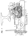
- Fig. 1 is a partially cutaway front view of a spinning reel for fishing according to a first embodiment of the invention.
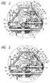
- Fig. 2 is a longitudinal sectional front view of the above reel, showing a state in which a normal drag mechanism is used.
- Fig. 3 is a longitudinal sectional front view of the above reel, showing a state in which a spool shaft is held in the freely rotatable state.
- Fig. 4 is a longitudinal sectional front view of the above reel, showing a state in which a rotor is held in the reversely rotatable state.
- Fig. 5 is a longitudinal sectional front view of the above reel, showing a state in which the spool shaft is held in the freely rotatable state.
- Fig. 6 is a longitudinal sectional side view of the main portions of the above reel.
- Fig. 7 is a section view taken along the line 7-7 of Fig. 6.
- Fig. 8 is a partially cutaway front view of a spinning reel for fishing according to a second embodiment of the invention.
- Fig. 9 is a longitudinal front view of the main portions of the second embodiment, showing the operating state thereof.
- Fig. 10 is a longitudinal front view of the main portions of the second embodiment, showing the operating state thereof.
- Fig. 11 is a side view of a reversal preventive device employed in the second embodiment, showing a state in which a rotor is prevented against reverse rotation.
- Fig. 12 is a side view of the above reversal preventive showing, showing a state in which a rotor is rotatable.
- Figs. 1 to 7 show a spinning reel for fishing according to a first embodiment of the present invention.
- a drag mechanism A having a friction brake member 1 and a control knob 3 for pressing the friction brake member 1 against a spool 2 is mounted to a front portion of a spool shaft 4 in a well known manner.
- the spool shaft 4 is supported by a reel main body 5 in such a manner that it can be slid axially and can be rotated. Further, the spool shaft 4 is coupled to a well-known reciprocative slide mechanism (not shown) so that the spool shaft 4 can be slid back and forth in linking with the rotation of a handle shaft 6 having a handle 6'.
- a transmission gear 7 is installed in a reel main body 5, which can be rotated integrally with the spool shaft 4 and slid relative to the spool shaft 4.
- the position of the transmission gear 7 in the axial direction of the spool shaft 4 is restricted by a support portion 5' of the reel main body 5.
- a linking shaft 9 is supported by the reel main body 5 at a position above the spool shaft 4 and in the rear portion of the interior of the reel main body 5.
- a driven gear 8 meshable with the transmission gear 7 is fixed to the linking shaft 9.
- the linking shaft 9 is formed with a cutaway circular or incomplete circular shaft portion 9' on which a securing gear 10 is provided.
- a switch-over member 11 is pivotably supported on the reel main body 5 so that the switch-over member 11 is engageable with and disengageable from the securing gear 10 and is energized in the engaging direction by a spring 11'.
- a switch-over mechanism B for switching the spool shaft 4 between the secured state and the freely rotatable state is structured.
- a reversal preventive device 16 is provided for the rotor 13 in an engageable and disengageable manner. That is, the reversal preventive device 16 is made up of a reversal preventive ratchet wheel 17 fixed to the rotor rotary shaft cylinder 14 and a securing pawl 18 which is engageable with and disengageable from the reversal preventive ratchet wheel 17 and is energized in the engaging direction by a spring 18'.
- a control plate 20 having an engaging recessed portion 19 is supported by the rear and upper portion of the reel main body 5 in such a manner that the control plate 20 can be slid back and forth with an operation knob 20', and a support piece 23 having a projection 21 engageable with the engaging recessed portion 19 is rotatably supported by a support shaft 22 which is axially supported by the reel main body 5. Therefore, if the control plate 20 is slid upwardly by the operation knob 20', then the support piece 23 is rotated about the support shaft 22 to move down the other leading end thereof as shown in Figs. 4 and 5.
- a linking mechanism C which includes a switch-over lever 24 and a rotary piece 25 both fixed integrally to the support shaft 22, and further includes a switch-over piece 26 pivotably supported on the leading end portion of the support piece 23, a connecting rod 27 pivotably supported on the respective leading end portions of the switch-over piece 26 and rotary piece 25, and a spring 28 for energizing the rotary piece 25 in the mutually opposing directions selectively. If the switch-over lever 24 is rotated from its front position shown in Fig. 4 to its rear position shown in Fig.
- an operation projecting portion 29 is formed the end portion of the switch-over member 11 opposite from the engaging end portion thereof in such a manner that it is engageable with the other engaging portion 25' of the rotary piece 25.
- the operation projection portion 29 is also engageable with or abuttable against a return projection 30 formed on the peripheral edge portion of the drive gear 12 when the switch-over member 11 is situated at a position spaced apart from the securing gear 10.
- the switch-over lever 24 is rotated downwardly from this state, as shown in Fig. 3, then the rotary piece 25 is rotated clockwise to thereby draw and rotate the switch-over piece 26 upwardly and, at the same time, the engaging portion 25' is engaged with the operation projecting portion 29 of the switch-over member 11 to push and rotate the same to thereby disengage the switch-over member 11 from the securing gear 10, so that the spool shaft 4 can be held in the freely rotatable state.
- the operation that the switch-over lever 24 is rotated upwardly suffices.
- the handle 6' may be rotated to rotate the drive gear 12.
- the rotation of the drive gear causes the return projection 30 to be brought into abutment with the operation projecting portion 29 to rotate both the switch-over member 11 and rotary piece 25 to thereby bring the switch-over member 11 into engagement with the securing gear 10 as well as to return the switch-over lever 24 to the upper position.
- the rotation of the switch-over lever 24 up to the upper position can return this state back to the state shown in Fig. 4.
- the drive gear 12 is rotated in the fishline take-up direction by rotating the handle 6, then the return projection 30 is brought into abutment with the operation projecting portion 29 to thereby rotate the switch-over member 11 and rotary piece 25, so that the current state can be returned to the state shown in Fig. 4.
- the switch-over lever 24 of the linking mechanism C and the operation knob 20' of the control device 20 selectively, it is possible to perform a normal fishing operation using the drag mechanism A as shown in Fig. 2, a fishing operation as shown in Figs. 3 and 5 in which the spool shaft is held in the freely rotatable state allowing the spool shaft to be rotated reversely, and a fishing operation as shown in Fig. 4 in which the rotor is held in the forwardly and reversely rotatable state allowing the rotor to be rotated reversely, selectively as desired.
- the switch-over operation between the forwardly and reversely rotatable state of the rotor shown in Fig. 4 and the freely rotatable state of the spool shaft can be performed quickly, easily and positively by the switch-over lever 24 or by an automatic return means using the rotation of the handle, which is very convenient for a fishing operation using these states successively or alternatively.
- the reversal preventive device of the rotor is connected with the switch-over mechanism for switching over the spool shaft between the drag operative state and the freely rotatable state by the linking mechanism in such a manner that, when the reversal preventive device prevents the reverse rotation of the rotor, the switch-over mechanism holds the spool shaft in the freely rotatable state and, when the reversal preventive device releases the prevention of the reverse rotation of the rotor, the switch-over mechanism holds the spool shaft in the secured state.
- the linking mechanism further includes control means which can switch over the reversal preventive device into the free state.
- the spinning reel for fishing permits selective and proper use of various fishing methods including a fishing method which uses the normal drag mechanism by means of the selective switch-over operation of the linking mechanism and control means, a fishing method which holds the spool shaft in the freely rotatable state, and a rotor reversible fishing method which holds the rotor in the reversely rotatable state; that is, the present spinning reel for fishing can deal with a wide variety of fishing methods.
- switch-over between the freely rotatable state of the spool and the reversely rotatable state of the rotor can be carried out quickly and easily only by operating the switch-over lever without switching over the reversal preventive device each time and, therefore, a fishing operation in which these switching operations must be carried out continuously can be performed positively as well as smoothly and quickly.
- the spinning reel according to the embodiment can deal with the above-mentioned various fishing operations only by providing a single reversal preventive device in the rotor and thus can simplify the structure thereof, so that the reel main body itself can be made light and compact.
- the switch-over operations to switch over the spool shaft from the freely rotatable state to the normal drag mechanism operative state and to switch over the rotor into the reversely rotatable state can be performed automatically by the automatic return means using the rotation of the handle in addition to the switch-over lever, so that the-above switch-over operations can be carried out more quickly, easily and positively. Due to this, the operationability and thus the utility value of the present spinning reel for fishing can be enhanced.
- Figs. 8 to 12 show a spinning reel for fishing according to a second embodiment of the present invention.
- a drag mechanism A having a friction brake member 101 and a control knob 103 for pressing the friction brake member 101 against a spool 102 is mounted in a well known manner in a front portion of a spool shaft 104.
- the spool shaft 104 is supported by a reel main body 105 in such a manner that it is slidable in the axial direction thereof and is also rotatable.
- a known reciprocative sliding mechanism (not shown) is provided for the spool shaft 104, and thus the spool shaft 104 can be slid back and forth in linking with the rotation of a handle shaft 106 including a handle 106'.
- a transmission gear 107 is held by the reel main body 105 and fitted on the spool shaft 104 such that it can be rotated integrally with the spool shaft 104 and can slide relative to the spool shaft 104.
- the position of the transmission gear 107 in the axial direction of the spool shaft 104 is restricted by a support portion 105' of the reel main body 105.
- a linking shaft 109 In the rear portion of the reel main body 105 located above the spool shaft 104, there is supported a linking shaft 109 to which is fixed a driven gear 8 meshable with the transmission gear 107.
- the linking shaft 109 is formed with a cutaway circular shaft portion 109' on which a securing gear 110 is provided integrally therewith.
- a switch-over member 111 which is engageable with and disengageable from the securing gear 110 and is energized in the engaging direction thereof by a spring 111'.
- a switch-over mechanism B is provided, which can switch over the spool shaft 104 between the secured state and freely rotatable state by engaging the switch-over member 111 with the securing gear 110 or disengaging the switch-over member 111 from the securing gear 110.
- a drive gear 112 which can be rotated through the handle shaft 106 when the handle 106' is rotated, is in mesh with a pinion 115 formed on a rotor rotary shaft cylinder 114 to which a rotor 113 is fixed.
- On the rotor rotary shaft cylinder 114 there are provided a first reversal preventive device 116 (corresponding to a second reversal preventive device in claims) and a second reversal preventive device 117 (corresponding to a first reversal preventive device in claims) for preventing the reverse rotation of the rotary shaft cylinder 114.
- the first reversal preventive device 116 includes a reversal preventive ratchet wheel 118 fixed to the portion of the rotor rotary shaft cylinder 114 existing in the outer front portion of the reel main body 105, a securing pawl 119 engageable with and disengageable from the reversal preventive ratchet wheel 118, and an operation lever 120 supported by the reel main body 105 for holding the securing pawl 119 in the engageable or disengageable state.
- the first reversal preventive device 116 is operated such that, if the securing pawl 119 is engaged with the reversal preventive ratchet wheel 118 by means of a switch-over cam 121 provided at the leading end of the operation lever 120, then the reverse rotation of the rotor 113 is prevented and, on the other hand, if the securing pawl 119 is disengaged from the reversal preventive ratchet wheel 118, then the rotor 113 is allowed to rotate reversely.
- the second reversal preventive device 117 includes a reversal preventive gear 122 fixed to the portion of the rotor rotary shaft cylinder 114 existing within the reel main body 105, an engaging pawl 124 having an operation projection piece 123 at one end thereof and engageable with and disengageable from the reversal preventive gear 122, and a spring 125 for energizing the engaging pawl 124 in the engaging direction thereof.
- the second reversal preventive device 117 is operated, similarly to the first reversal preventive device 116, such that, if the engaging pawl 124 is in engagement, then the reverse rotation of the rotor 113 is prevented and, if disengaged, then the reverse rotation of the rotor 113 is allowed.
- the second reversal preventive device 117 and the switch-over mechanism B are structured such that they can be operated in linking with each other by a linking mechanism C including a switch-over lever 127. That is, the linking mechanism C includes an operation piece 128, which is pivotably supported by the reel main body 105 and provided with the switch-over lever 127 the position of which can be regulated selectively in the back and forth direction of the reel main body 105 by an energization spring 126, and a connecting rod 129 slidably supported by the reel main body 105.
- One end of the connecting rod 129 is pivotably supported by a projecting portion 128' provided on the operation piece 128, the projecting portion 128' is engageable with an operation portion 111'' formed in the switch-over member 111 included in the switch-over mechanism A, and a folded projecting piece 129' formed in the other end of the connecting rod 129 is engageable with the operation projection piece 123 of the engaging pawl 124 to be able to draw the same rearwardly.
- the embodiment of the invention is structured in the above-mentioned manner, in a state in which the securing pawl 119 is engaged with the reversal preventive ratchet wheel 118 by the operation lever 120 of the reversal preventive device 116 to thereby prevent the reverse rotation of the rotor, when the switch-over lever 127 of the linking mechanism C is rotated and positioned in the front, upper portion of the reel main body 105 as shown in Fig.
- the operation piece 128 draws the connecting rod 129 and the folded projecting piece 129' of the connecting rod 129 in turn draws the operation projection piece 123 of the engaging pawl 124 of the second reversal preventive device 117 to thereby disengage the securing pawl 124 from the reversal preventive gear 122, while the switch-over member 111 of the switch-over mechanism B is energized by the spring 111' so that it is engaged with the securing gear 110 and is thereby secured to the spool shaft 104. Consequently, the spool shaft 104 is held in a fixed state and the spool 102 is now held in a state in which fishing due to a normal drag brake operation by the friction brake member 101 can be played.
- the first reversal preventive device 116 and second reversal preventive device 117 for preventing the reverse rotation of the rotor are both provided in the rotor rotary shaft cylinder 114.
- the first reversal preventive device 116 can be provided in the handle shaft 106.
- the linking mechanism including the switch-lever can be replaced with other equivalent means, but the slidable connecting rod system employed in the above-mentioned embodiment is advantageous in that the operation thereof can be performed smoothly and a more simplified structure can be provided.
- the second reversal preventive device in the rotor and the second reversal preventive device is connected to the switch-over mechanism for switching over the spool shaft between the drag operation state and the freely rotatable state by the linking mechanism, while the linking mechanism is structured such that, when the second reversal preventive device prevents the reverse rotation of the rotor, the switch-over mechanism holds the spool shaft in the freely rotatable state and, when the second reversal preventive device removes the prevention of the reversal rotation of the rotor, the switch-over mechanism holds the spool shaft in the secured state.
- a fishing method which uses the normal drag mechanism by means of the rotor reversal preventive device and the switch-over operation of the linking mechanism, a fishing method which holds the spool in the freely rotatable state, and a rotor reversible fishing method which holds the rotor in the reversible state can be selectively used to suit the occasion, thereby allowing the invention to be applied over a wide range of fishing methods.
- the switch-over operation between the freely rotatable state of the spool and the forwardly and reversely rotatable state of the rotor can be made quickly and easily without performing the switch-over operation of the rotor reversal preventive device each time. This makes it possible to perform positively, smoothly and quickly a fishing operation in which these switch-over operations must be performed continuously.
- the first reversal preventive device and second reversal preventive device are respectively disposed in the inside and outside of the reel box on the rotor rotary shaft cylinder, it is possible to secure a sufficient space for installation of the linking mechanism and thus the present spinning reel for fishing can be made compact without enlarging the size of the reel main body.
Landscapes
- Life Sciences & Earth Sciences (AREA)
- Environmental Sciences (AREA)
- Animal Husbandry (AREA)
- Biodiversity & Conservation Biology (AREA)
Abstract
Description
- The present invention relates to a spinning reel for fishing, and, in particular, to a switch-over mechanism capable of switching over a spool between a drag operation state and a freely rotatable state, which is installed in the spinning reel.
- A drag mechanism for a spinning reel for fishing is generally structured such that a drag force can be controlled gradually by rotating a drag control knob. However, an actual fishing requires various kinds of operations: for example, an operation for switching over a spool from the drag operative state to the freely rotatable state while maintaining a state where the reverse rotation of a rotor is prevented with a rotor reversal preventive device, an operation for switching the spool over to the drag operative state immediately after fish is caught in a state that the spool is held in the freely rotatable state, and so on, in order to prevent a fishline from being cut, to prevent the mouth of fish caught from being damaged or cut away, and to facilitate deep biting of fish. In order to be able to deal with the above fishing operations, an arrangement in which a drag mechanism can be switched over between the drag operative state and the spool freely rotatable state is proposed, as disclosed in Japanese Patent Publications Sho. 61-274638, Hei. 2-405 and the like.
- Further, the actual fishing requires so-called rotor reversible fishing operation: That is, the reverse rotation preventive state of the reversal preventive device is released to set for the rotor a forwardly and reversely rotatable state that the rotor can be rotated forwardly or reversely by rotating a handle to play out or take up the fishline. This rotor reversible fishing operation is usable, for instance, in such a situate that an angler wishes to move the position of the terminal tackles closer or further when he awaits the biting of the fish awaited with the spool held in the spool freely rotatable state.
- However, in order to perform the rotor reversible fishing operation, the prevention of the reverse rotation of the rotor by the rotor reversal preventive device must be released each time and at the same time the spool must be switched into the secured state. Similarly, in order to switch the rotor reversible fishing state over to the spool freely rotatable state, the rotor reversal preventive device must be switched over to the rotor reversal preventive state as well as the switch-over mechanism must be switched from the secured state to the freely rotatable state. If the angler forgets this necessary switch-over operation, then the spool and rotor will be rotated together, so that the fishline may be slacked off or the fishline cannot be played out smoothly.
- Accordingly, it is an object of the invention to provide a spinning reel for fishing which not only can deal with the above-mentioned various fishing operations easily and positively but also is simplified in structure and is improved in operationability.
- In order to attain the above-noted and other objects, the invention provides, as a preferred embodiment, a spinning reel for fishing in which a spool having a drag mechanism is provided in the front portion of a spool shaft which can be reciprocated back and forth by rotating a handle. A switch-over mechanism is provided for the spool shaft to switch over the spool shaft between a secured state and a freely rotatable state. An engageable and disengageable reversal preventive device is provided for a rotor to selectively prevent the reverse rotation of the rotor. Further, a linking mechanism having a switch-over lever is provided between the switch-over mechanism and reversal preventive device. The linking mechanism is structured in such a manner that, when the switch-over mechanism secures the spool shaft, the reversal preventive device releases the prevention of the reverse rotation of the rotor and, when the switch-over mechanism holds the spool shaft in the freely rotatable state, the reversal preventive device secures the rotor. The linking mechanism may be provided with a control means for switching over the reversal preventive device between the engaged and disengaged states thereof when the switch-over mechanism secures the spool shaft. Another reverse rotation preventive device may be provided for the rotor alternatively.
- To return the linking and switch-over mechanisms from their positions for the spool shaft freely rotatable state back to their positions for the spool shaft secured state, the switch-over lever of the linking mechanism is operated manually. Alternatively, there may be provided a return projection in a drive gear and an operation projecting portion in a switch-over member included in the switch-over mechanism in such a manner that the return projection can be brought into abutment with the operation projecting portion. With this structure, the return operation can be performed automatically by means of the rotational operation of the handle. That is, this structure is further advantageous in that it can realize a better return operation.
- Fig. 1 is a partially cutaway front view of a spinning reel for fishing according to a first embodiment of the invention.
- Fig. 2 is a longitudinal sectional front view of the above reel, showing a state in which a normal drag mechanism is used.
- Fig. 3 is a longitudinal sectional front view of the above reel, showing a state in which a spool shaft is held in the freely rotatable state.
- Fig. 4 is a longitudinal sectional front view of the above reel, showing a state in which a rotor is held in the reversely rotatable state.
- Fig. 5 is a longitudinal sectional front view of the above reel, showing a state in which the spool shaft is held in the freely rotatable state.
- Fig. 6 is a longitudinal sectional side view of the main portions of the above reel.
- Fig. 7 is a section view taken along the line 7-7 of Fig. 6.
- Fig. 8 is a partially cutaway front view of a spinning reel for fishing according to a second embodiment of the invention.
- Fig. 9 is a longitudinal front view of the main portions of the second embodiment, showing the operating state thereof.
- Fig. 10 is a longitudinal front view of the main portions of the second embodiment, showing the operating state thereof.
- Fig. 11 is a side view of a reversal preventive device employed in the second embodiment, showing a state in which a rotor is prevented against reverse rotation.
- Fig. 12 is a side view of the above reversal preventive showing, showing a state in which a rotor is rotatable.
- Preferred embodiments of the present invention will now be described with reference to the drawings attached hereto.
- Figs. 1 to 7 show a spinning reel for fishing according to a first embodiment of the present invention.
- In the spinning reel, a drag mechanism A having a
friction brake member 1 and acontrol knob 3 for pressing thefriction brake member 1 against aspool 2 is mounted to a front portion of aspool shaft 4 in a well known manner. Thespool shaft 4 is supported by a reelmain body 5 in such a manner that it can be slid axially and can be rotated. Further, thespool shaft 4 is coupled to a well-known reciprocative slide mechanism (not shown) so that thespool shaft 4 can be slid back and forth in linking with the rotation of ahandle shaft 6 having a handle 6'. - A
transmission gear 7 is installed in a reelmain body 5, which can be rotated integrally with thespool shaft 4 and slid relative to thespool shaft 4. The position of thetransmission gear 7 in the axial direction of thespool shaft 4 is restricted by a support portion 5' of the reelmain body 5. A linkingshaft 9 is supported by the reelmain body 5 at a position above thespool shaft 4 and in the rear portion of the interior of the reelmain body 5. A drivengear 8 meshable with thetransmission gear 7 is fixed to the linkingshaft 9. The linkingshaft 9 is formed with a cutaway circular or incomplete circular shaft portion 9' on which asecuring gear 10 is provided. On the other hand, a switch-overmember 11 is pivotably supported on the reelmain body 5 so that the switch-overmember 11 is engageable with and disengageable from thesecuring gear 10 and is energized in the engaging direction by a spring 11'. Thus, a switch-over mechanism B for switching thespool shaft 4 between the secured state and the freely rotatable state is structured. - A
drive gear 12, which is provided on thehandle shaft 6, is meshed with apinion 15 formed in a rotorrotary shaft cylinder 14 to which arotor 13 is fixed. A reversalpreventive device 16 is provided for therotor 13 in an engageable and disengageable manner. That is, the reversalpreventive device 16 is made up of a reversalpreventive ratchet wheel 17 fixed to the rotorrotary shaft cylinder 14 and a securingpawl 18 which is engageable with and disengageable from the reversalpreventive ratchet wheel 17 and is energized in the engaging direction by aspring 18'. - On the other hand, a
control plate 20 having an engagingrecessed portion 19 is supported by the rear and upper portion of the reelmain body 5 in such a manner that thecontrol plate 20 can be slid back and forth with an operation knob 20', and asupport piece 23 having aprojection 21 engageable with the engaging recessedportion 19 is rotatably supported by asupport shaft 22 which is axially supported by the reelmain body 5. Therefore, if thecontrol plate 20 is slid upwardly by the operation knob 20', then thesupport piece 23 is rotated about thesupport shaft 22 to move down the other leading end thereof as shown in Figs. 4 and 5. - Also, in the rear and upper portion of the reel
main body 5, there is provided a linking mechanism C which includes a switch-overlever 24 and arotary piece 25 both fixed integrally to thesupport shaft 22, and further includes a switch-overpiece 26 pivotably supported on the leading end portion of thesupport piece 23, a connectingrod 27 pivotably supported on the respective leading end portions of the switch-overpiece 26 androtary piece 25, and aspring 28 for energizing therotary piece 25 in the mutually opposing directions selectively. If the switch-over lever 24 is rotated from its front position shown in Fig. 4 to its rear position shown in Fig. 5, then therotary piece 25 rotates the switch-overpiece 26 clockwise through the connectingrod 27 to thereby release the pressing action to a projectingpiece 18'' provided in thesecuring pawl 18 of the reversalpreventive device 16. Thus, thesecuring pawl 18 is engaged with the reversalpreventive pawl 17 due to the energization force of thespring 18'. - Further, an
operation projecting portion 29 is formed the end portion of the switch-overmember 11 opposite from the engaging end portion thereof in such a manner that it is engageable with the other engaging portion 25' of therotary piece 25. Theoperation projection portion 29 is also engageable with or abuttable against areturn projection 30 formed on the peripheral edge portion of thedrive gear 12 when the switch-overmember 11 is situated at a position spaced apart from thesecuring gear 10. Therefore, if thedrive gear 12 is rotated by rotating thehandle shaft 6, then thereturn projection 30 is brought into abutment with theoperation projecting portion 29 of the switch-overmember 11 at the spaced position to push and rotate the switch-overmember 11 to thereby engage the same with thesecuring gear 10, as well as to rotate therotary piece 25 counterclockwise against thespring 28 to thereby return the switch-lever 24 to the upper rotary position. - Next, the operation of the spinning reel thus constructed will be described hereafter.
- If the operation knob 20' is switched over to the lower position and the switch-
over lever 24 is switched over to the upper rotary position as shown in Fig. 2, then the securingpawl 18 of the reversalpreventive device 16 is engaged with the reversalpreventive ratchet wheel 17 to thereby prevent the reverse rotation of therotor 13 and, at the same time, the switch-overmember 11 of the switch-over mechanism B is engaged with thesecuring gear 10 to thereby secure thespool shaft 4, which makes it possible to perform a normal fishing operation using the drag mechanism A. - Next, if the switch-over
lever 24 is rotated downwardly from this state, as shown in Fig. 3, then therotary piece 25 is rotated clockwise to thereby draw and rotate the switch-overpiece 26 upwardly and, at the same time, the engaging portion 25' is engaged with theoperation projecting portion 29 of the switch-overmember 11 to push and rotate the same to thereby disengage the switch-overmember 11 from thesecuring gear 10, so that thespool shaft 4 can be held in the freely rotatable state. To return this state again to the state shown in Fig. 2, the operation that the switch-overlever 24 is rotated upwardly suffices. Alternatively, the handle 6' may be rotated to rotate thedrive gear 12. That is, the rotation of the drive gear causes thereturn projection 30 to be brought into abutment with theoperation projecting portion 29 to rotate both the switch-over member 11 androtary piece 25 to thereby bring the switch-over member 11 into engagement with the securinggear 10 as well as to return the switch-overlever 24 to the upper position. - Next, in the state shown in Fig. 2, if the
control plate 20 is slid up to the upper position by use of the operation knob 20' as shown in Fig. 4, then thesupport piece 23 in engagement with the engaging recessedportion 19 of thecontrol plate 20 is rotated counterclockwise by means of the projection to move down the switch-over piece 26 into pressure engagement with the projectingpiece 18'' of the securingpawl 18 to thereby disengage the securingpawl 18 from the reversalpreventive ratchet wheel 17 against the force of thespring 18', so that therotor 13 is switched over to the forwardly and reversely rotatable state and thus the rotor reversible fishing is possible. - Also, as shown in Fig. 5, if the switch-over
lever 24 is rotated down to the lower position from the above state, then the switch-over piece 26 is pulled upwardly by means of the rotation of therotary piece 25 through the connectingrod 27 to release the pressure engagement action of the switch-over piece 26 onto the projectingpiece 18'' of the securingpawl 18, so that the securingpawl 18 is brought into engagement with the reversalpreventive ratchet wheel 17 due to the energization force of thespring 18' to thereby prevent the reverse rotation of therotor 13, and simultaneously the engaging portion 25' of therotary piece 25 is pressed against theoperation projecting portion 29 to thereby disengage the switch-over member 11 from the securinggear 10, so that thespool shaft 4 is now held in the freely rotatable state. The rotation of the switch-overlever 24 up to the upper position can return this state back to the state shown in Fig. 4. Alternatively, if thedrive gear 12 is rotated in the fishline take-up direction by rotating thehandle 6, then thereturn projection 30 is brought into abutment with theoperation projecting portion 29 to thereby rotate the switch-over member 11 androtary piece 25, so that the current state can be returned to the state shown in Fig. 4. - As has been described heretofore, by operating the switch-over
lever 24 of the linking mechanism C and the operation knob 20' of thecontrol device 20 selectively, it is possible to perform a normal fishing operation using the drag mechanism A as shown in Fig. 2, a fishing operation as shown in Figs. 3 and 5 in which the spool shaft is held in the freely rotatable state allowing the spool shaft to be rotated reversely, and a fishing operation as shown in Fig. 4 in which the rotor is held in the forwardly and reversely rotatable state allowing the rotor to be rotated reversely, selectively as desired. In particular, the switch-over operation between the forwardly and reversely rotatable state of the rotor shown in Fig. 4 and the freely rotatable state of the spool shaft can be performed quickly, easily and positively by the switch-overlever 24 or by an automatic return means using the rotation of the handle, which is very convenient for a fishing operation using these states successively or alternatively. - According to the first embodiment of the present invention, the reversal preventive device of the rotor is connected with the switch-over mechanism for switching over the spool shaft between the drag operative state and the freely rotatable state by the linking mechanism in such a manner that, when the reversal preventive device prevents the reverse rotation of the rotor, the switch-over mechanism holds the spool shaft in the freely rotatable state and, when the reversal preventive device releases the prevention of the reverse rotation of the rotor, the switch-over mechanism holds the spool shaft in the secured state. Further, the linking mechanism further includes control means which can switch over the reversal preventive device into the free state. Thanks to this, the spinning reel for fishing according to the embodiment permits selective and proper use of various fishing methods including a fishing method which uses the normal drag mechanism by means of the selective switch-over operation of the linking mechanism and control means, a fishing method which holds the spool shaft in the freely rotatable state, and a rotor reversible fishing method which holds the rotor in the reversely rotatable state; that is, the present spinning reel for fishing can deal with a wide variety of fishing methods. Especially, switch-over between the freely rotatable state of the spool and the reversely rotatable state of the rotor can be carried out quickly and easily only by operating the switch-over lever without switching over the reversal preventive device each time and, therefore, a fishing operation in which these switching operations must be carried out continuously can be performed positively as well as smoothly and quickly.
- Also, the spinning reel according to the embodiment can deal with the above-mentioned various fishing operations only by providing a single reversal preventive device in the rotor and thus can simplify the structure thereof, so that the reel main body itself can be made light and compact.
- Further, according to the embodiment, the switch-over operations to switch over the spool shaft from the freely rotatable state to the normal drag mechanism operative state and to switch over the rotor into the reversely rotatable state can be performed automatically by the automatic return means using the rotation of the handle in addition to the switch-over lever, so that the-above switch-over operations can be carried out more quickly, easily and positively. Due to this, the operationability and thus the utility value of the present spinning reel for fishing can be enhanced.
- Figs. 8 to 12 show a spinning reel for fishing according to a second embodiment of the present invention.
- A drag mechanism A having a
friction brake member 101 and acontrol knob 103 for pressing thefriction brake member 101 against aspool 102 is mounted in a well known manner in a front portion of aspool shaft 104. Thespool shaft 104 is supported by a reelmain body 105 in such a manner that it is slidable in the axial direction thereof and is also rotatable. A known reciprocative sliding mechanism (not shown) is provided for thespool shaft 104, and thus thespool shaft 104 can be slid back and forth in linking with the rotation of ahandle shaft 106 including a handle 106'. - A
transmission gear 107 is held by the reelmain body 105 and fitted on thespool shaft 104 such that it can be rotated integrally with thespool shaft 104 and can slide relative to thespool shaft 104. The position of thetransmission gear 107 in the axial direction of thespool shaft 104 is restricted by a support portion 105' of the reelmain body 105. In the rear portion of the reelmain body 105 located above thespool shaft 104, there is supported a linkingshaft 109 to which is fixed a drivengear 8 meshable with thetransmission gear 107. The linkingshaft 109 is formed with a cutaway circular shaft portion 109' on which asecuring gear 110 is provided integrally therewith. On the other hand, in the reelmain body 105, there is supported a switch-overmember 111 which is engageable with and disengageable from thesecuring gear 110 and is energized in the engaging direction thereof by a spring 111'. In this manner, a switch-over mechanism B is provided, which can switch over thespool shaft 104 between the secured state and freely rotatable state by engaging the switch-overmember 111 with thesecuring gear 110 or disengaging the switch-overmember 111 from thesecuring gear 110. - A
drive gear 112, which can be rotated through thehandle shaft 106 when the handle 106' is rotated, is in mesh with apinion 115 formed on a rotorrotary shaft cylinder 114 to which arotor 113 is fixed. On the rotorrotary shaft cylinder 114, there are provided a first reversal preventive device 116 (corresponding to a second reversal preventive device in claims) and a second reversal preventive device 117 (corresponding to a first reversal preventive device in claims) for preventing the reverse rotation of therotary shaft cylinder 114. - In particular, the first reversal
preventive device 116 includes a reversalpreventive ratchet wheel 118 fixed to the portion of the rotorrotary shaft cylinder 114 existing in the outer front portion of the reelmain body 105, a securingpawl 119 engageable with and disengageable from the reversalpreventive ratchet wheel 118, and anoperation lever 120 supported by the reelmain body 105 for holding the securingpawl 119 in the engageable or disengageable state. The first reversalpreventive device 116 is operated such that, if the securingpawl 119 is engaged with the reversalpreventive ratchet wheel 118 by means of a switch-overcam 121 provided at the leading end of theoperation lever 120, then the reverse rotation of therotor 113 is prevented and, on the other hand, if the securingpawl 119 is disengaged from the reversalpreventive ratchet wheel 118, then therotor 113 is allowed to rotate reversely. - Also, the second reversal
preventive device 117 includes a reversalpreventive gear 122 fixed to the portion of the rotorrotary shaft cylinder 114 existing within the reelmain body 105, an engagingpawl 124 having anoperation projection piece 123 at one end thereof and engageable with and disengageable from the reversalpreventive gear 122, and aspring 125 for energizing theengaging pawl 124 in the engaging direction thereof. The second reversalpreventive device 117 is operated, similarly to the first reversalpreventive device 116, such that, if the engagingpawl 124 is in engagement, then the reverse rotation of therotor 113 is prevented and, if disengaged, then the reverse rotation of therotor 113 is allowed. - The second reversal
preventive device 117 and the switch-over mechanism B are structured such that they can be operated in linking with each other by a linking mechanism C including a switch-overlever 127. That is, the linking mechanism C includes anoperation piece 128, which is pivotably supported by the reelmain body 105 and provided with the switch-overlever 127 the position of which can be regulated selectively in the back and forth direction of the reelmain body 105 by anenergization spring 126, and a connectingrod 129 slidably supported by the reelmain body 105. One end of the connectingrod 129 is pivotably supported by a projecting portion 128' provided on theoperation piece 128, the projecting portion 128' is engageable with an operation portion 111'' formed in the switch-overmember 111 included in the switch-over mechanism A, and a folded projecting piece 129' formed in the other end of the connectingrod 129 is engageable with theoperation projection piece 123 of the engagingpawl 124 to be able to draw the same rearwardly. - Since the embodiment of the invention is structured in the above-mentioned manner, in a state in which the securing
pawl 119 is engaged with the reversalpreventive ratchet wheel 118 by theoperation lever 120 of the reversalpreventive device 116 to thereby prevent the reverse rotation of the rotor, when the switch-overlever 127 of the linking mechanism C is rotated and positioned in the front, upper portion of the reelmain body 105 as shown in Fig. 9, theoperation piece 128 draws the connectingrod 129 and the folded projecting piece 129' of the connectingrod 129 in turn draws theoperation projection piece 123 of the engagingpawl 124 of the second reversalpreventive device 117 to thereby disengage the securingpawl 124 from the reversalpreventive gear 122, while the switch-overmember 111 of the switch-over mechanism B is energized by the spring 111' so that it is engaged with thesecuring gear 110 and is thereby secured to thespool shaft 104. Consequently, thespool shaft 104 is held in a fixed state and thespool 102 is now held in a state in which fishing due to a normal drag brake operation by thefriction brake member 101 can be played. - After then, when the switch-over
lever 127 of the linking mechanism C is rotated to a backward lower position shown in Fig. 10 from the above state, the projecting portion 128' of theoperation piece 128 is engaged with the operation portion 111'' of the switch-overmember 111 of the switch-over mechanism B to rotate the switch-overmember 111 counterclockwise to thereby disengage the same from thesecuring gear 110 and, at the same time, the folded projecting piece 129' of the connectingrod 129 removes its drawing action of theoperation projection piece 123 of the engagingpawl 124 so that the engagingpawl 124 can be engaged with the reversalpreventive gear 122 due to the energizing force of thespring 125. Consequently, while therotor 113 is prevented from rotation by both the first reversalpreventive device 116 and second reversalpreventive device 117, thespool shaft 104 is switched over into the freely rotatable state, so that thespool 102 can be held in the freely rotatable state. - Also, in a state in which the securing
pawl 119 of the reversalpreventive device 116 is disengaged from the reversalpreventive ratchet wheel 118 by theoperation lever 120 as shown in Fig. 12, if the switch-overlever 127 of the linking mechanism C is rotated and positioned at a front, upper position shown in Fig. 9, then the engagingpawl 124 of the second reversalpreventive device 117 is disengaged from the reversalpreventive gear 122 and the switch-overmember 111 of the switch-over mechanism B is engaged with thesecuring gear 110 to thereby hold thespool shaft 104 in the secured state, so that therotor 113 can be rotated forwardly and reversely and thus the rotor reversible fishing can be played. - Further, in this state, if the switch-over
lever 127 is rotated and positioned at the back, lower position as shown in Fig. 10, then the engagingpawl 124 of the secondpreventive device 117 is engaged with the reversepreventive gear 122 to thereby prevent the reverse rotation of therotor 113 and the switch-overmember 111 of the switch-over mechanism B is disengaged from thesecuring gear 110, so that thespool shaft 104 can be held in the freely rotatable state. - In the above-mentioned embodiment, the first reversal
preventive device 116 and second reversalpreventive device 117 for preventing the reverse rotation of the rotor are both provided in the rotorrotary shaft cylinder 114. However, this is not limitative, but alternatively, the first reversalpreventive device 116 can be provided in thehandle shaft 106. Also, the linking mechanism including the switch-lever can be replaced with other equivalent means, but the slidable connecting rod system employed in the above-mentioned embodiment is advantageous in that the operation thereof can be performed smoothly and a more simplified structure can be provided. - As has been described heretofore, according to the embodiment of the invention, there is provided the second reversal preventive device in the rotor and the second reversal preventive device is connected to the switch-over mechanism for switching over the spool shaft between the drag operation state and the freely rotatable state by the linking mechanism, while the linking mechanism is structured such that, when the second reversal preventive device prevents the reverse rotation of the rotor, the switch-over mechanism holds the spool shaft in the freely rotatable state and, when the second reversal preventive device removes the prevention of the reversal rotation of the rotor, the switch-over mechanism holds the spool shaft in the secured state. Thanks to this, a fishing method which uses the normal drag mechanism by means of the rotor reversal preventive device and the switch-over operation of the linking mechanism, a fishing method which holds the spool in the freely rotatable state, and a rotor reversible fishing method which holds the rotor in the reversible state can be selectively used to suit the occasion, thereby allowing the invention to be applied over a wide range of fishing methods. In particular, the switch-over operation between the freely rotatable state of the spool and the forwardly and reversely rotatable state of the rotor can be made quickly and easily without performing the switch-over operation of the rotor reversal preventive device each time. This makes it possible to perform positively, smoothly and quickly a fishing operation in which these switch-over operations must be performed continuously.
- Also, according to the embodiment, due to the fact that the first reversal preventive device and second reversal preventive device are respectively disposed in the inside and outside of the reel box on the rotor rotary shaft cylinder, it is possible to secure a sufficient space for installation of the linking mechanism and thus the present spinning reel for fishing can be made compact without enlarging the size of the reel main body.
Claims (11)
- A spinning reel for fishing, comprising:
a reel main body;
a spool rotatably arranged with respect to said reel main body;
a drag mechanism for frictionally coupling said spool to said reel main body;
a rotor rotatably arranged with respect to said reel main body for winding a fishline onto said spool;
a switch-over mechanism for switching over said spool between a secured state and a freely rotatable state;
a first reversal preventive device for switching over said rotor between a first reversal preventive state and a first reversal permissible state;
a linking mechanism having a switch-over lever for coupling said switch-over mechanism to said first reversal preventive device such that said first reversal preventive device is activated to switch said rotor into said reversal permissible state when said switch-over mechanism switches said spool into said secured state, and that said first reversal preventive device is activated to switch said rotor into said reversal preventive state when said switch-over mechanism switches said spool into said freely rotatable state. - A spinning reel for fishing according to claim 1, further comprising:
control means for switching over said rotor between a second reversal preventive state and a second reversal permissible state when said spool is in said secured state. - A spinning reel for fishing according to claim 1, further comprising:
control means connected to said linking mechanism to selectively suppress function of said linking mechanism such that said first reversal preventive device can not switch said rotor from said first reversal preventive state to said first reversal permissible state even if said switch-over mechanism switches said spool from said freely rotatable state to said secured state. - A spinning reel for fishing according to claim 1, further comprising:
automatic return means for returning said spool from said freely rotatable state to said secured state in linking with rotation of a handle. - A spinning reel for fishing according to claim 1, further comprising:
a second reversal preventive device for switching over said rotor between a second reversal preventive state and a second reversal permissible state, said second reversal preventive device being independently operated from said first reversal preventive device. - A spinning reel for fishing according to claim 1, wherein said spool is frictionally coupled to said reel main body through said drag mechanism when said spool is in said secured state, and said spool is free from said reel main body when said spool is in said freely rotatable state.
- A spinning reel for fishing according to claim 1, wherein said rotor is rotatable in a first direction and is prevented from rotating in a second direction opposite to said first direction when said rotor is in said first reversal preventive state, and said rotor is rotatable in both said first and second direction in linking with a handle when said rotor is in said first reversal permissible state.
- A spinning reel for fishing according to claim 2, wherein said rotor is rotatable in a first direction and is prevented from rotating in a second direction opposite to said first direction when said rotor is in said second reversal preventive state, and said rotor is rotatable in both said first and second direction in linking with a handle when said rotor is in said second reversal permissible state.
- A spinning reel for fishing according to claim 5, wherein said rotor is rotatable in a first direction and is prevented from rotating in a second direction opposite to said first direction when said rotor is in at least one of said first and second reversal preventive state.
- A spinning reel for fishing according to claim 9, wherein said rotor is rotatable in both said first and second directions in linking with a handle when said rotor is in both of said first and second reversal permissible states.
- A spinning reel for fishing according to claim 5, wherein both of said first and second reverse rotation preventive device is provided on a rotary quill to which said rotor is fixed.
Applications Claiming Priority (4)
| Application Number | Priority Date | Filing Date | Title |
|---|---|---|---|
| JP49980/94 | 1994-02-24 | ||
| JP4998094A JP2886076B2 (en) | 1994-02-24 | 1994-02-24 | Spinning reel for fishing |
| JP5831194A JP2925922B2 (en) | 1994-03-04 | 1994-03-04 | Spinning reel for fishing |
| JP58311/94 | 1994-03-04 |
Publications (2)
| Publication Number | Publication Date |
|---|---|
| EP0670112A1 true EP0670112A1 (en) | 1995-09-06 |
| EP0670112B1 EP0670112B1 (en) | 1997-07-09 |
Family
ID=26390411
Family Applications (1)
| Application Number | Title | Priority Date | Filing Date |
|---|---|---|---|
| EP95102446A Expired - Lifetime EP0670112B1 (en) | 1994-02-24 | 1995-02-21 | Spinning reel for fishing |
Country Status (6)
| Country | Link |
|---|---|
| US (1) | US5593102A (en) |
| EP (1) | EP0670112B1 (en) |
| KR (1) | KR100290699B1 (en) |
| DE (1) | DE69500402T2 (en) |
| DK (1) | DK0670112T3 (en) |
| GB (1) | GB2287165B (en) |
Families Citing this family (9)
| Publication number | Priority date | Publication date | Assignee | Title |
|---|---|---|---|---|
| KR100304065B1 (en) * | 1993-10-21 | 2001-11-22 | 마쯔이 요시유끼 | Drag device of spinning reel for fishing |
| US6123280A (en) * | 1999-06-28 | 2000-09-26 | Heligear Engineering (Hk) Co., Ltd. | Fishing reel switchable stepless anti-reverse mechanism with plunger locator |
| JP3585782B2 (en) * | 1999-09-01 | 2004-11-04 | ダイワ精工株式会社 | Spinning reel for fishing |
| KR100332052B1 (en) * | 1999-11-05 | 2002-06-03 | 오철석 | Spinning reel with drag brake mechanism and clutch |
| US6446893B2 (en) * | 1999-11-30 | 2002-09-10 | Daiwa Seiko, Inc. | Spinning reel for fishing |
| JP4809265B2 (en) * | 2007-02-23 | 2011-11-09 | グローブライド株式会社 | Fishing spinning reel |
| JP5481101B2 (en) * | 2009-06-08 | 2014-04-23 | シマノコンポネンツ マレーシア エスディーエヌ.ビーエッチディー. | Drag switching device for spinning reel |
| KR102453699B1 (en) * | 2014-09-30 | 2022-10-14 | 글로브라이드 가부시키가이샤 | Reverse rotation preventing device for fishing reel |
| AT523749B1 (en) * | 2020-04-21 | 2022-01-15 | Gollner Johann | fishing reel |
Citations (3)
| Publication number | Priority date | Publication date | Assignee | Title |
|---|---|---|---|---|
| JPS61274638A (en) * | 1985-05-30 | 1986-12-04 | 株式会社シマノ | Spinning reel |
| US4650134A (en) * | 1985-07-25 | 1987-03-17 | Brunswick Corporation | Dual anti-reverse and self-centering mechanism for spinning reels |
| US4746077A (en) * | 1985-05-30 | 1988-05-24 | Shimano Industrial Company Limited | Control device for a drag mechanism in a spinning type fishing reel |
Family Cites Families (9)
| Publication number | Priority date | Publication date | Assignee | Title |
|---|---|---|---|---|
| SE7905746L (en) * | 1979-07-02 | 1981-01-03 | Abu Ab | DEVICE OF A DISCONNECTABLE LOCKING MECHANISM BY A FISHER ROLL |
| US4634074A (en) * | 1984-11-22 | 1987-01-06 | Kabushiki Kaisha Ohmori Seisakusho | Spinning type fishing reel with line untwisting capability |
| JPH0244713Y2 (en) * | 1985-05-24 | 1990-11-27 | ||
| US4834307A (en) * | 1988-06-01 | 1989-05-30 | Abu Garcia Produktion Ab | Open fixed-spool fishing reel |
| JP2524565B2 (en) * | 1989-04-07 | 1996-08-14 | ダイワ精工株式会社 | Spinning reel for fishing |
| US5201477A (en) * | 1989-04-11 | 1993-04-13 | Shimano, Inc. | Spinning reel with drag brake mechanism and clutch |
| KR910002135Y1 (en) * | 1989-04-22 | 1991-04-04 | 주식회사 은성사 | Spool apparatus for fixhing reel |
| DK0429923T3 (en) * | 1989-11-17 | 1996-07-01 | Daiwa Seiko Inc | Brake mechanism in a fishing reel for fishing |
| US5470027A (en) * | 1991-08-06 | 1995-11-28 | Zebco Corporation | Antireverse assembly for a fishing reel |
-
1995
- 1995-02-17 GB GB9503154A patent/GB2287165B/en not_active Expired - Fee Related
- 1995-02-21 DE DE69500402T patent/DE69500402T2/en not_active Expired - Fee Related
- 1995-02-21 EP EP95102446A patent/EP0670112B1/en not_active Expired - Lifetime
- 1995-02-21 DK DK95102446.2T patent/DK0670112T3/en active
- 1995-02-21 US US08/391,348 patent/US5593102A/en not_active Expired - Lifetime
- 1995-02-23 KR KR1019950003494A patent/KR100290699B1/en not_active IP Right Cessation
Patent Citations (3)
| Publication number | Priority date | Publication date | Assignee | Title |
|---|---|---|---|---|
| JPS61274638A (en) * | 1985-05-30 | 1986-12-04 | 株式会社シマノ | Spinning reel |
| US4746077A (en) * | 1985-05-30 | 1988-05-24 | Shimano Industrial Company Limited | Control device for a drag mechanism in a spinning type fishing reel |
| US4650134A (en) * | 1985-07-25 | 1987-03-17 | Brunswick Corporation | Dual anti-reverse and self-centering mechanism for spinning reels |
Also Published As
| Publication number | Publication date |
|---|---|
| GB2287165B (en) | 1997-10-15 |
| KR100290699B1 (en) | 2001-06-01 |
| GB9503154D0 (en) | 1995-04-05 |
| DE69500402T2 (en) | 1997-10-23 |
| DK0670112T3 (en) | 1997-12-08 |
| US5593102A (en) | 1997-01-14 |
| DE69500402D1 (en) | 1997-08-14 |
| GB2287165A (en) | 1995-09-13 |
| KR950030783A (en) | 1995-12-18 |
| EP0670112B1 (en) | 1997-07-09 |
Similar Documents
| Publication | Publication Date | Title |
|---|---|---|
| EP0429923B1 (en) | Drag mechanism in spinning reel for fishing | |
| EP0406898B1 (en) | Spinning reel for fishing | |
| EP0649595B1 (en) | Drag device in spinning reel for fishing | |
| US5593102A (en) | Spinning reel for fishing having a mechanism for linking the spool reverse preventive and the drag device | |
| US4881699A (en) | Rotor-locking mechanism for a fishing reel | |
| GB2258595A (en) | Spinning reel having a device for preventing backward rotation of a rotor. | |
| JPH0697933B2 (en) | Spinning reel | |
| EP0766916B1 (en) | Spinning reel for fishing | |
| US4477038A (en) | Click device with a line sagging prevention mechanism for a fishing reel | |
| US4899952A (en) | Double bearing type fishing reel | |
| JP3576836B2 (en) | Spinning reel for fishing | |
| JP2895727B2 (en) | Drag device for spinning reel for fishing | |
| JPH025734Y2 (en) | ||
| US4640471A (en) | Clutch releasing and braking mechanism for fishing reel | |
| JP2886076B2 (en) | Spinning reel for fishing | |
| US5775613A (en) | Anti-reverse system for a fishing reel | |
| JP2925922B2 (en) | Spinning reel for fishing | |
| JP3495584B2 (en) | Spinning reel for fishing | |
| KR950005831Y1 (en) | Drag mechanism in spinning reel for fishing | |
| JP2895728B2 (en) | Drag device for spinning reel for fishing | |
| JP2886060B2 (en) | Drag device for spinning reel for fishing | |
| JPH0746151Y2 (en) | Switching device for drag mechanism of spinning reel for fishing | |
| JP2535336Y2 (en) | Brake mechanism for double bearing reel | |
| JPH0631462U (en) | Rear drag mechanism of spinning reel for fishing | |
| JPS6135804B2 (en) |
Legal Events
| Date | Code | Title | Description |
|---|---|---|---|
| PUAI | Public reference made under article 153(3) epc to a published international application that has entered the european phase |
Free format text: ORIGINAL CODE: 0009012 |
|
| AK | Designated contracting states |
Kind code of ref document: A1 Designated state(s): DE DK FR IT SE |
|
| 17P | Request for examination filed |
Effective date: 19960116 |
|
| 17Q | First examination report despatched |
Effective date: 19960216 |
|
| GRAG | Despatch of communication of intention to grant |
Free format text: ORIGINAL CODE: EPIDOS AGRA |
|
| GRAH | Despatch of communication of intention to grant a patent |
Free format text: ORIGINAL CODE: EPIDOS IGRA |
|
| GRAH | Despatch of communication of intention to grant a patent |
Free format text: ORIGINAL CODE: EPIDOS IGRA |
|
| GRAA | (expected) grant |
Free format text: ORIGINAL CODE: 0009210 |
|
| AK | Designated contracting states |
Kind code of ref document: B1 Designated state(s): DE DK FR IT SE |
|
| REF | Corresponds to: |
Ref document number: 69500402 Country of ref document: DE Date of ref document: 19970814 |
|
| ITF | It: translation for a ep patent filed | ||
| ET | Fr: translation filed | ||
| REG | Reference to a national code |
Ref country code: DK Ref legal event code: T3 |
|
| PG25 | Lapsed in a contracting state [announced via postgrant information from national office to epo] |
Ref country code: DK Free format text: LAPSE BECAUSE OF NON-PAYMENT OF DUE FEES Effective date: 19980302 |
|
| PLBE | No opposition filed within time limit |
Free format text: ORIGINAL CODE: 0009261 |
|
| STAA | Information on the status of an ep patent application or granted ep patent |
Free format text: STATUS: NO OPPOSITION FILED WITHIN TIME LIMIT |
|
| 26N | No opposition filed | ||
| PGFP | Annual fee paid to national office [announced via postgrant information from national office to epo] |
Ref country code: SE Payment date: 19990204 Year of fee payment: 5 |
|
| REG | Reference to a national code |
Ref country code: DK Ref legal event code: EBP |
|
| PG25 | Lapsed in a contracting state [announced via postgrant information from national office to epo] |
Ref country code: SE Free format text: LAPSE BECAUSE OF NON-PAYMENT OF DUE FEES Effective date: 20000222 |
|
| EUG | Se: european patent has lapsed |
Ref document number: 95102446.2 |
|
| PGFP | Annual fee paid to national office [announced via postgrant information from national office to epo] |
Ref country code: FR Payment date: 20030210 Year of fee payment: 9 |
|
| PGFP | Annual fee paid to national office [announced via postgrant information from national office to epo] |
Ref country code: DE Payment date: 20030306 Year of fee payment: 9 |
|
| PG25 | Lapsed in a contracting state [announced via postgrant information from national office to epo] |
Ref country code: DE Free format text: LAPSE BECAUSE OF NON-PAYMENT OF DUE FEES Effective date: 20040901 |
|
| PG25 | Lapsed in a contracting state [announced via postgrant information from national office to epo] |
Ref country code: FR Free format text: LAPSE BECAUSE OF NON-PAYMENT OF DUE FEES Effective date: 20041029 |
|
| REG | Reference to a national code |
Ref country code: FR Ref legal event code: ST |
|
| PG25 | Lapsed in a contracting state [announced via postgrant information from national office to epo] |
Ref country code: IT Free format text: LAPSE BECAUSE OF NON-PAYMENT OF DUE FEES;WARNING: LAPSES OF ITALIAN PATENTS WITH EFFECTIVE DATE BEFORE 2007 MAY HAVE OCCURRED AT ANY TIME BEFORE 2007. THE CORRECT EFFECTIVE DATE MAY BE DIFFERENT FROM THE ONE RECORDED. Effective date: 20050221 |