EP0669234A1 - Steering lock for motor vehicles with blocking device for the locking bolt - Google Patents
Steering lock for motor vehicles with blocking device for the locking bolt Download PDFInfo
- Publication number
- EP0669234A1 EP0669234A1 EP95102069A EP95102069A EP0669234A1 EP 0669234 A1 EP0669234 A1 EP 0669234A1 EP 95102069 A EP95102069 A EP 95102069A EP 95102069 A EP95102069 A EP 95102069A EP 0669234 A1 EP0669234 A1 EP 0669234A1
- Authority
- EP
- European Patent Office
- Prior art keywords
- locking
- bolt
- stator
- latch
- rotation
- Prior art date
- Legal status (The legal status is an assumption and is not a legal conclusion. Google has not performed a legal analysis and makes no representation as to the accuracy of the status listed.)
- Granted
Links
- 230000000903 blocking effect Effects 0.000 title claims description 20
- 238000013519 translation Methods 0.000 claims abstract description 9
- 230000033001 locomotion Effects 0.000 claims description 3
- 230000000149 penetrating effect Effects 0.000 claims description 2
- 230000003213 activating effect Effects 0.000 abstract 5
- 230000006835 compression Effects 0.000 description 3
- 238000007906 compression Methods 0.000 description 3
- 238000013461 design Methods 0.000 description 3
- 238000000605 extraction Methods 0.000 description 3
- 230000009471 action Effects 0.000 description 2
- 210000003323 beak Anatomy 0.000 description 2
- 230000000694 effects Effects 0.000 description 2
- 230000007246 mechanism Effects 0.000 description 2
- 230000036961 partial effect Effects 0.000 description 2
- 238000006243 chemical reaction Methods 0.000 description 1
- 230000000295 complement effect Effects 0.000 description 1
- 238000006073 displacement reaction Methods 0.000 description 1
- 239000000284 extract Substances 0.000 description 1
- 230000004048 modification Effects 0.000 description 1
- 238000012986 modification Methods 0.000 description 1
- 230000000051 modifying effect Effects 0.000 description 1
- 230000000750 progressive effect Effects 0.000 description 1
- 230000000717 retained effect Effects 0.000 description 1
- 239000007858 starting material Substances 0.000 description 1
- 239000010902 straw Substances 0.000 description 1
Images


Classifications
-
- B—PERFORMING OPERATIONS; TRANSPORTING
- B60—VEHICLES IN GENERAL
- B60R—VEHICLES, VEHICLE FITTINGS, OR VEHICLE PARTS, NOT OTHERWISE PROVIDED FOR
- B60R25/00—Fittings or systems for preventing or indicating unauthorised use or theft of vehicles
- B60R25/01—Fittings or systems for preventing or indicating unauthorised use or theft of vehicles operating on vehicle systems or fittings, e.g. on doors, seats or windscreens
- B60R25/02—Fittings or systems for preventing or indicating unauthorised use or theft of vehicles operating on vehicle systems or fittings, e.g. on doors, seats or windscreens operating on the steering mechanism
- B60R25/021—Fittings or systems for preventing or indicating unauthorised use or theft of vehicles operating on vehicle systems or fittings, e.g. on doors, seats or windscreens operating on the steering mechanism restraining movement of the steering column or steering wheel hub, e.g. restraining means controlled by ignition switch
- B60R25/0211—Fittings or systems for preventing or indicating unauthorised use or theft of vehicles operating on vehicle systems or fittings, e.g. on doors, seats or windscreens operating on the steering mechanism restraining movement of the steering column or steering wheel hub, e.g. restraining means controlled by ignition switch comprising a locking member radially and linearly moved towards the steering column
- B60R25/02115—Fittings or systems for preventing or indicating unauthorised use or theft of vehicles operating on vehicle systems or fittings, e.g. on doors, seats or windscreens operating on the steering mechanism restraining movement of the steering column or steering wheel hub, e.g. restraining means controlled by ignition switch comprising a locking member radially and linearly moved towards the steering column key actuated
- B60R25/02118—Fittings or systems for preventing or indicating unauthorised use or theft of vehicles operating on vehicle systems or fittings, e.g. on doors, seats or windscreens operating on the steering mechanism restraining movement of the steering column or steering wheel hub, e.g. restraining means controlled by ignition switch comprising a locking member radially and linearly moved towards the steering column key actuated with linear bolt motion parallel to the lock axis
-
- E—FIXED CONSTRUCTIONS
- E05—LOCKS; KEYS; WINDOW OR DOOR FITTINGS; SAFES
- E05B—LOCKS; ACCESSORIES THEREFOR; HANDCUFFS
- E05B17/00—Accessories in connection with locks
- E05B17/04—Devices for coupling the turning cylinder of a single or a double cylinder lock with the bolt operating member
Definitions
- the present invention relates to a motor vehicle steering lock.
- a motor vehicle steering lock essentially consists of a locking bolt which is received in a housing formed in a rotary member of the steering column, under the action of a return spring which can be retracted, to release the steering column, by a barrel lock.
- the object of the present invention is to remedy the drawbacks which have just been mentioned.
- housing 10 associated with the housing for guiding the steering column in rotation (not shown) which is of generally cylindrical shape and an internal bore 12 of which receives, fixed in rotation and in axial translation, a stator 14 .
- the stator 14 is an element of generally cylindrical annular shape, a first front part 16 of which is arranged in the bore 12 and a second rear part 18 of which is arranged outside of the bore 12 and of the housing 10, these two parts being separated by a radial shoulder 20 which defines the axial position of the stator 14 relative to the housing 10.
- the housing 10 also comprises a passage 22 forming a slide which receives in sliding, in an axial direction parallel to the axis of the bore 12 and the stator 14, a locking bolt 24 which is slidably mounted between its locking position illustrated in FIG. 1 in which its front end 26 projects outside the passage 22 to be received in a housing (not shown) of the steering shaft ( Figure 1) and a retracted position for unlocking the steering column in which its front face 26 is recessed and inside the corridor 22 ( Figure 4).
- the bolt 24 has an oblong cross section complementary to that of the corridor 22 in order to avoid the rotation of this element around its axis.
- the bolt 24 is connected in axial translation to a pull tab 28 by means of a connecting tab 30 received in a buttonhole 32 formed in the front part 34 of the pull tab.
- the pull tab is slidably received in a guide slot 36 formed in the front part 16 of the stator 14.
- a locking spring 38 is constituted by a helical compression spring which is intended to be received in a cylindrical housing 40 formed in the front part 16 of the stator 14 to axially bias the bolt 24, towards its position of locking, illustrated in FIG. 1, by acting on a reaction tab 42 formed on the upper face 29 of the pull tab 28.
- the pull tab 28 and the bolt 24 are thus permanently biased axially forwards in the locking position of the steering column.
- the pull tab 28 also carries a finger or pin 44 for controlling its axial movements.
- the control finger 44 extends vertically below the lower face 27 of the pull tab 28 to cooperate with the face opposite a control cam 46 which is formed in the outer cylindrical wall 48 of a rotary actuator 50.
- the rotary actuating member 50 has a generally cylindrical shape and it is mounted for rotation in a cylindrical bore formed for this purpose in the wall of the front part 16 of the stator 14.
- the rotary actuating member comprises a finger 54 for indexing the angular position of the member 50 relative to the stator 14 which is biased by a spring 56 and which can be received in two notches 58 and 60 (FIG. 6) formed in the concave cylindrical wall 52 of the bore of the front part 16 of the stator 14.
- the rear transverse radial face 62 of the rotary actuating member 50 bears axially against the bottom 64 of the bore 52 of the part front 16 of the stator 14 and it has a recess 66 in which a locking latch 68 is arranged.
- the latch 68 is in the form of a lever which is pivotally mounted in the housing 66 around a pivot 70 whose axis is parallel to the axis of rotation of the member 50.
- a first branch 72 of the latch 68 is an abutment branch which limits the tilting stroke of the latch 68 around its pivot 70, clockwise by considering for example Figures 6, 8 and 9, and whose lower face 74 cooperates with a stop surface 76 facing the housing 66.
- the locking latch 68 comprises a second branch 78, longer than the first branch 72, the lower face 80 of which faces the transverse bottom 76 of the housing 66.
- the upper face 82 of the latch 68 comprises a control ramp 84 which extends in a plane parallel to the axis of the pivot 70 and which is extended, in the vicinity of the free end 86 of the latch 68, by a blocking spout 88 which can be received in a notch 90 formed in the free rear edge 92 of the pull tab 28.
- the front bottom 94 of the notch 90 constitutes a transverse abutment surface of the pull tab 28 against the blocking spout 88 when the latter is received in the notch 90.
- the blocking latch 68 is resiliently urged in permanent rotation around its pivot 70, clockwise by considering FIG. 6, by a helical compression spring 96 which is received in a housing 98 formed in the lower face 80 of the latch 68 and which also bears against a U-shaped flake 98 which is guided in a slot 100 which extends in a radial plane.
- the upper face 102 of the locking spout 88 is a flat surface portion which is capable of cooperating with the lower face 27 of the pull tab 28 as will be explained below.
- the rear face 62 of the rotary actuating member 50 comprises a blind T-shaped housing 104 which allows the member 50 to be driven in rotation by the shaft of outlet 106 of the rotary barrel 108 of a lock 110.
- the shaft 106 comprises drive studs 112 arranged in T and in relief which are received in the housing 104.
- the body 114 of the lock 110 is immobilized in rotation relative to the stator 14 in the rear part 18 from which it is received and which for this purpose comprises an axial angular indexing stud 116.
- the barrel 108 comprises housings intended to receive glitter (not shown) which, depending on the presence or not of a key in the slot 120 of the barrel 108, allow or not the rotation of the latter and therefore the rotation of the output shaft 106 which is linked in rotation to the rotary actuating member 50.
- the axial end of the shaft 106 of the barrel 108 which is received through a central cylindrical housing 122 of the rotary actuating member 50 has a slot 124 which receives the straw 98, the latter thus ensuring the axial attachment of the barrel 108 on the drive member 50.
- FIG. 2 also shows a spring 126 for return to starter which acts on the drive member 50.
- the anti-theft device finally comprises a lever 130 called the security lever.
- the lever 130 is pivotally mounted in the stator 14 around a pivot axis 132 which is perpendicular to the axis of rotation of the rotary drive member 50.
- a first branch 134 of the lever 130 has at its free end a safety spout 136 which is designed to be received in a slot 138 which is formed longitudinally in the pull tab 28 fixed to the bolt 24.
- the end 140 of the second branch 142 of the safety lever 130 is received in a slider 144 which is slidably mounted in the rear part 18 of the stator 14, in a vertical direction perpendicular to the axis of rotation of the rotary member d drive 50 and barrel 108, and whose end 146 located radially inside is capable of cooperating with a cam surface for controlling the pivoting of the safety lever 130 which is formed at the periphery of barrel 108 as can be see it in figure 5.
- the control cam surface has a cylindrical portion of larger diameter 148 and a ramp 150 which leads to a cylindrical cam portion (not shown in FIG. 5) of smaller diameter than the portion 148.
- the safety lever 130 is elastically biased in permanent rotation about its axis 132 by a helical compression spring 152 which is received in a housing 154 formed in the stator and which is supported on a bearing surface 156 formed in the face upper part of the second branch 142 of the safety lever 130 in order to urge the latter in rotation about its axis 132, counterclockwise by considering, for example, Figures 1 and 4, so as to urge the slider 144 in sliding radially towards the interior towards barrel 108.
- the locking spout 88 of the locking latch 68 is received in the notch 90 and the pull tab 28 cannot therefore be moved, like the bolt 24, against the locking spring 38, even if the bolt 24 is axially stressed inside the passage 22 and the steering column therefore remains blocked in rotation by the bolt 24.
- the driver can then rotate the barrel 108, in the clockwise direction indicated by the arrow not referenced in FIG. 1.
- This rotation causes the retraction of the blocking spout 88 of the blocking latch 68 due to the cooperation of the ramp 84 with the opposite control surface portion 85 formed in the cylindrical bore 52 of the front part. 16 of the stator 14, and causes the progressive retraction of the bolt 24 and of the pull tab 28 inside the device under the action of the cooperation of the control finger 44 with the control cam 46 of the rotary actuating member 48.
- the indexing finger of the rotary actuating member 50 has passed from notch 58 to notch 60 and, as can be seen in FIGS. 4 and 8, the locking latch 68 is retracted to the interior of the stator 14, 16, that is to say that the upper face 102 of the locking spout 88 is in abutment against the portion of cylindrical surface facing 52 of the stator.
- the slide 144 causes the safety lever 130 to pivot about its axis 132 , clockwise by considering FIGS. 1 and 4, which has the effect of causing the safety beak 136 to penetrate into the lumen 138 which is then opposite the safety beak 136.
- the driver causes a rotation in the opposite direction, that is to say in the counterclockwise direction, considering FIG. 8, of the rotary member d actuation 50 to firstly, just before the extraction of the key, in the intermediate position illustrated in Figures 5 and 9 in which the safety lever 130 has not yet released the pull tab 28 and in which the face upper 102 of the locking spout 88 of the locking latch 68 is in abutment against the lower face 29 of the pull tab 28.
Landscapes
- Engineering & Computer Science (AREA)
- Mechanical Engineering (AREA)
- Lock And Its Accessories (AREA)
- Steering Controls (AREA)
Abstract
Description
La présente invention concerne un antivol de direction de véhicule automobile.The present invention relates to a motor vehicle steering lock.
Selon la conception la plus répandue d'un antivol de direction de véhicule automobile, celui-ci est essentiellement constitué par un pêne de verrouillage qui est reçu dans un logement formé dans un organe rotatif de la colonne de direction, sous l'action d'un ressort de rappel et qui peut être escamoté, pour libérer la colonne de direction, par un verrou à barillet.According to the most widespread design of a motor vehicle steering lock, it essentially consists of a locking bolt which is received in a housing formed in a rotary member of the steering column, under the action of a return spring which can be retracted, to release the steering column, by a barrel lock.
Toutes ces conceptions ont pour inconvénient de présenter la possibilité, pour un voleur, de repousser le pêne, à l'encontre de son ressort de verrouillage, et de permettre ainsi au voleur de libérer la colonne de direction sans avoir à agir sur le verrou.All these designs have the drawback of presenting the possibility, for a thief, of pushing the bolt, against its locking spring, and thus allowing the thief to release the steering column without having to act on the lock.
Diverses solutions ont été proposées pour bloquer le pêne en position de verrouillage.Various solutions have been proposed to lock the bolt in the locked position.
Une solution est décrite et représentée dans le document FR-A-2.590.924 qui est spécifique à un verrou à barillet coulissant et qui est particulièrement complexe à mettre en oeuvre dans la mesure où elle nécessite de modifier la structure même du verrou à barillet coulissant.A solution is described and represented in document FR-A-2,590,924 which is specific to a sliding barrel lock and which is particularly complex to implement since it requires modifying the very structure of the sliding barrel lock .
D'autres solutions ont été proposées qui visent à bloquer le pêne de verrouillage et à ne le libérer qu'après une rotation déterminée du barillet d'un verrou à barillet rotatif. Ces solutions sont toutefois particulièrement complexes et coûteuses à mettre en oeuvre et nécessitent également de modifier la conception classique du verrou à barillet tournant.Other solutions have been proposed which aim to block the locking bolt and to release it only after a determined rotation of the barrel of a rotary barrel lock. These solutions are however particularly complex and costly to implement and also require modification of the conventional design of the rotary barrel lock.
La présente invention a pour but de remédier aux inconvénients qui viennent d'être mentionnés.The object of the present invention is to remedy the drawbacks which have just been mentioned.
Dans ce but, l'invention propose un antivol de direction de véhicule automobile contenant :
- - un organe rotatif d'actionnement comportant une came de commande du mouvement d'escamotage d'un pêne de verrouillage, à l'encontre de l'effort de rappel exercé sur le pêne par un ressort de verrouillage, qui est susceptible de pivoter entre une position angulaire extrême de verrouillage d'un élément d'une colonne de direction dont un logement reçoit le pêne de verrouillage et une position angulaire extrême de déverrouillage dans laquelle le pêne de verrouillage est en position escamotée ;
- - un rotor d'entraînement manuel en rotation de l'organe rotatif d'actionnement entre ses deux positions angulaires extrêmes ; et
- - des moyens escamotables de blocage qui immobilisent en translation le pêne de verrouillage lorsque l'organe rotatif d'actionnement est dans sa position angulaire extrême de verrouillage, et dont la libération est commandée par la rotation de l'organe rotatif d'actionnement, caractérisé en ce qu'il comporte un stator dans lequel l'organe rotatif d'actionnement est monté à rotation et en ce que les moyens de blocage comportent un loquet monté basculant sur l'organe rotatif d'actionnement autour d'un pivot dont l'axe est parallèle à l'axe de rotation de l'organe rotatif d'actionnement, entre une position de blocage vers laquelle il est rappelé élastiquement et dans laquelle un bec de blocage du loquet coopère avec une surface de butée du pêne et une position de repos dans laquelle le bec de blocage est effacé en retrait par rapport à la surface de butée, le loquet de blocage comportant une surface de came de commande des mouvements de basculement du loquet qui coopère avec une surface de commande formée en vis-à-vis dans le stator. Selon d'autres caractéristiques de l'invention :
- - le bec de blocage est formé au voisinage d'une extrémité libre du loquet et il est susceptible de pénétrer dans une encoche formée dans le pêne ;
- - la surface de came est une portion de surface plane inclinée formant rampe qui s'étend dans un plan parallèle à l'axe du loquet ;
- - en position de repos du loquet, l'extrémité libre du bec de blocage est sollicitée élastiquement en appui contre une surface de portée cylindrique circulaire formée en vis-à-vis dans le stator ;
- - le pêne de verrouillage est lié en translation à une tirette réalisée sous la forme d'une plaque montée coulissante dans le stator, parallèlement à l'axe de rotation de l'organe rotatif d'actionnement, et qui porte un doigt transversal de commande qui coopère avec la came formée sur l'organe rotatif d'actionnement ;
- - l'encoche est formée dans la tirette ;
- - l'antivol comporte une levier de sécurité monté pivotant sur le stator autour d'un axe perpendiculaire à l'axe de rotation de l'organe rotatif d'actionnement entre une position de repos vers laquelle il est rappelé élastiquement et une position de sécurité dans laquelle un bec de sécurité formé sur le levier de sécurité est reçu dans une lumière longitudinale formée dans le pêne pour immobiliser ce dernier en position escamotée lorsque l'organe rotatif d'actionnement est dans sa position extrême de déverrouillage, et dont le pivotement est commandé par des moyens de commande associés au rotor d'entraînement manuel ;
- - le rotor d'entraînement manuel est constitué par le barillet d'un verrou rotatif dont le corps est lié en rotation au stator ;
- - les moyens de commande du pivotement du levier de sécurité sont constitués par une came de sécurité qui agit sur une extrémité libre d'un bras du levier de sécurité.
- - a rotary actuating member comprising a cam for controlling the retraction movement of a locking bolt, against the return force exerted on the bolt by a locking spring, which is capable of pivoting between an extreme angular position for locking an element of a steering column of which a housing receives the locking bolt and an extreme angular position for unlocking in which the locking bolt is in the retracted position;
- - A manual drive rotor in rotation of the rotary actuating member between its two extreme angular positions; and
- - retractable locking means which immobilize in translation the locking bolt when the rotary actuating member is in its extreme angular locking position, and the release of which is controlled by the rotation of the rotary actuating member, characterized in that it comprises a stator in which the rotary actuating member is mounted for rotation and in that the locking means comprise a latch mounted to tilt on the rotary actuating member around a pivot, the axis is parallel to the axis of rotation of the rotary actuating member, between a blocking position towards which it is resiliently recalled and in which a latch blocking spout cooperates with a bolt stop surface and a position rest in which the blocking spout is retracted with respect to the abutment surface, the blocking latch comprising a cam surface for controlling the tilting movements of the latch which cooperates e with a control surface formed opposite in the stator. According to other characteristics of the invention:
- - The blocking spout is formed in the vicinity of a free end of the latch and it is capable of penetrating a notch formed in the bolt;
- - The cam surface is an inclined flat surface portion forming a ramp which extends in a plane parallel to the axis of the latch;
- - In the rest position of the latch, the free end of the blocking spout is elastically urged to bear against a surface of circular cylindrical bearing formed opposite in the stator;
- - The locking bolt is linked in translation to a pull rod produced in the form of a plate mounted to slide in the stator, parallel to the axis of rotation of the rotary actuating member, and which carries a transverse control finger. which cooperates with the cam formed on the rotary actuating member;
- - the notch is formed in the pull tab;
- - the anti-theft device comprises a security lever pivotally mounted on the stator around an axis perpendicular to the axis of rotation of the rotary actuating member between a rest position towards which it is resiliently recalled and a security position in which a safety spout formed on the safety lever is received in a longitudinal opening formed in the bolt to immobilize the latter in the retracted position when the rotary actuating member is in its extreme unlocking position, and the pivoting of which is controlled by control means associated with the manual drive rotor;
- - The manual drive rotor is constituted by the barrel of a rotary lock whose body is linked in rotation to the stator;
- the means for controlling the pivoting of the safety lever consist of a safety cam which acts on a free end of an arm of the safety lever.
D'autres caractéristiques et avantages de l'invention apparaîtront à la lecture de la description détaillée qui va suivre pour la compréhension de laquelle on se reportera aux dessins annexés dans lesquels :
- - La figure 1 est une vue schématique en perspective, avec des arrachements partiels, d'un exemple de réalisation d'un antivol conforme aux enseignements de l'invention et qui est illustré en position verrouillée de la colonne de direction ;
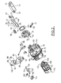
- - la figure 2 est une vue en perspective éclatée des principaux composants du mécanisme de l'antivol qui sont agencés dans le boîtier de ce dernier ;
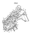
- - la figure 3 est une vue schématique en perspective de certains des composants illustrés sur la figure 1 ;
- - la figure 4 est une vue similaire à celle de la figure 1 sur laquelle l'antivol est illustré en position déverrouillée de la colonne de direction avec son pêne escamoté à l'intérieur du boîtier;
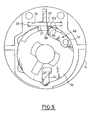
- - la figure 5 est une vue schématique partielle en perspective de certains des composants du mécanisme de l'antivol qui sont illustrés dans la position qu'ils occupent juste avant le blocage du pêne en position verrouillée avant l'extraction de la clef du verrou ;
- - la figure 6 est une vue schématique en bout selon la flèche F6 de la figure 3 ;
- - la figure 7 est une vue schématique en bout selon la flèche F7 de la figure 3 ;
- - la figure 8 est une vue similaire à celle de la figure 6 qui illustre les composants dans la position qu'ils occupent lorsque l'antivol est dans sa position illustrée sur la figure 4 ; et
- - la figure 9 est une vue similaire à celle de la figure 6 qui illustre les composants dans la position qu'ils occupent lorsque l'antivol est dans sa position illustrée sur la figure 5.
- - Figure 1 is a schematic perspective view, with partial cutaway, of an embodiment of an anti-theft device according to the teachings of the invention and which is illustrated in the locked position of the steering column;
- - Figure 2 is an exploded perspective view of the main components of the anti-theft mechanism which are arranged in the housing of the latter;
- - Figure 3 is a schematic perspective view of some of the components illustrated in Figure 1;
- - Figure 4 is a view similar to that of Figure 1 in which the lock is illustrated in the unlocked position of the steering column with its bolt retracted inside the housing;
- - Figure 5 is a partial schematic perspective view of some of the components of the anti-theft mechanism which are illustrated in the position they occupy just before blocking the bolt in the locked position before the extraction of the lock key;
- - Figure 6 is a schematic end view along arrow F6 of Figure 3;
- - Figure 7 is a schematic end view along arrow F7 of Figure 3;
- - Figure 8 is a view similar to that of Figure 6 which illustrates the components in the position they occupy when the lock is in its position illustrated in Figure 4; and
- FIG. 9 is a view similar to that of FIG. 6 which illustrates the components in the position they occupy when the anti-theft device is in its position illustrated in FIG. 5.
On a représenté sur les figures un boîtier 10 associé au boîtier de guidage en rotation de la colonne de direction (non représentée) qui est de forme générale cylindrique et dont un alésage interne 12 reçoit, fixé en rotation et en translation axiale, un stator 14.There is shown in the figures a
Le stator 14 est un élément de forme générale annulaire cylindrique dont une première partie avant 16 est agencée dans l'alésage 12 et dont une seconde partie arrière 18 est agencée à l'extérieur de l'alésage 12 et du boîtier 10, ces deux parties étant séparées par un épaulement radial 20 qui définit la position axiale du stator 14 par rapport au boîtier 10.The
A sa partie avant, à droite en considérant les figures 1 à 5, le boîtier 10 comporte également un couloir 22 formant glissière qui reçoit en coulissement, selon une direction axiale parallèle à l'axe de l'alésage 12 et du stator 14, un pêne de verrouillage 24 qui est monté coulissant entre sa position de verrouillage illustrée sur la figure 1 dans laquelle son extrémité avant 26 fait saillie à l'extérieur du couloir 22 pour être reçue dans un logement (non représenté) de l'arbre de direction (figure 1) et une position escamotée de déverrouillage de la colonne de direction dans laquelle sa face avant 26 est en retrait et à l'intérieur du couloir 22 (figure 4).At its front part, on the right considering Figures 1 to 5, the
Le pêne 24 présente une section transversale oblongue complémentaire de celle du couloir 22 afin d'éviter la rotation de cet élément autour de son axe.The
Le pêne 24 est relié en translation axiale à une tirette 28 par l'intermédiaire d'une patte de liaison 30 reçue dans une boutonnière 32 formée dans la partie avant 34 de la tirette.The
La tirette est reçue en coulissement dans une fente de guidage 36 formée dans la partie avant 16 du stator 14.The pull tab is slidably received in a
Un ressort de verrouillage 38, illustré sur la figure 2, est constitué par un ressort hélicoïdal de compression qui est prévu pour être reçu dans un logement cylindrique 40 formé dans la partie avant 16 du stator 14 pour solliciter axialement le pêne 24, vers sa position de verrouillage, illustrée sur la figure 1, en agissant sur une patte de réaction 42 formée sur la face supérieure 29 de la tirette 28.A
La tirette 28 et le pêne 24 sont ainsi en permanence sollicités axialement vers l'avant en position de verrouillage de la colonne de direction.The
La tirette 28 porte également un doigt ou pion 44 de commande de ses déplacements axiaux.The
Le doigt de commande 44 s'étend verticalement en dessous de la face inférieure 27 de la tirette 28 pour coopérer avec la face en vis-à-vis d'une came de commande 46 qui est formée dans la paroi cylindrique extérieure 48 d'un organe rotatif d'actionnement 50.The
L'organe rotatif d'actionnement 50 présente une forme générale cylindrique et il est monté à rotation dans un alésage cylindrique formé à cet effet dans la paroi de la partie avant 16 du stator 14.The rotary actuating
L'organe rotatif d'actionnement comporte un doigt 54 d'indexation en position angulaire de l'organe 50 par rapport au stator 14 qui est sollicité par un ressort 56 et qui peut être reçu dans deux crans 58 et 60 (figure 6) formés dans la paroi cylindrique concave 52 de l'alésage de la partie avant 16 du stator 14.The rotary actuating member comprises a
La face radiale transversale arrière 62 de l'organe rotatif d'actionnement 50 prend appui axialement contre le fond 64 de l'alésage 52 de la partie avant 16 du stator 14 et elle comporte un évidement 66 dans lequel est agencé un loquet de blocage 68.The rear transverse
Le loquet 68 se présente sous la forme d'un levier qui est monté pivotant dans le logement 66 autour d'un pivot 70 dont l'axe est parallèle à l'axe de rotation de l'organe 50.The
Une première branche 72 du loquet 68 est une branche de butée qui limite la course de basculement du loquet 68 autour de son pivot 70, dans le sens horaire en considérant par exemple les figures 6, 8 et 9, et dont la face inférieure 74 coopère avec une surface de butée 76 en vis-à-vis du logement 66.A
Le loquet de blocage 68 comporte une seconde branche 78, plus longue que la première branche 72 dont la face inférieure 80 est tournée vers le fond transversal 76 du logement 66.The locking
La face supérieure 82 du loquet 68 comporte une rampe de commande 84 qui s'étend dans un plan parallèle à l'axe du pivot 70 et qui se prolonge, au voisinage de l'extrémité libre 86 du loquet 68, par un bec de blocage 88 qui est susceptible d'être reçu dans une encoche 90 formée dans le bord arrière libre 92 de la tirette 28.The
Le fond avant 94 de l'encoche 90 constitue une surface transversale de butée de la tirette 28 contre le bec de blocage 88 lorsque ce dernier est reçu dans l'encoche 90.The
Le loquet de blocage 68 est sollicité élastiquement en permanence en rotation autour de son pivot 70, dans le sens horaire en considérant la figure 6, par un ressort hélicoïdal de compression 96 qui est reçu dans un logement 98 formé dans la face inférieure 80 du loquet 68 et qui prend d'autre part appui contre une paillette en forme de U 98 qui est guidée dans une fente 100 qui s'étend dans un plan radial.The blocking
La face supérieure 102 du bec de blocage 88 est une portion de surface plane qui est susceptible de coopérer avec la face inférieure 27 de la tirette 28 comme cela sera expliqué par la suite.The
Comme on peut le voir notamment sur la figure 3, la face arrière 62 de l'organe rotatif d'actionnement 50 comporte un logement borgne en forme de T 104 qui permet l'entraînement en rotation de l'organe 50 par l'arbre de sortie 106 du barillet rotatif 108 d'un verrou 110.As can be seen in particular in FIG. 3, the
A cet effet, l'arbre 106 comporte des plots d'entraînement 112 agencés en T et en relief qui sont reçus dans le logement 104.To this end, the
Le corps 114 du verrou 110 est immobilisé en rotation par rapport au stator 14 dans la partie arrière 18 duquel il est reçu et qui comporte à cet effet un plot axial d'indexation angulaire 116.The
Selon une conception connue, le barillet 108 comporte des logements destinés à recevoir des paillettes (non représentées) qui, en fonction de la présence ou non d'une clef dans la fente 120 du barillet 108, permettent ou non la rotation de ce dernier et donc la rotation de l'arbre de sortie 106 qui est lié en rotation à l'organe rotatif d'actionnement 50.According to a known design, the
L'extrémité axiale de l'arbre 106 du barillet 108 qui est reçue à travers un logement cylindrique central 122 de l'organe rotatif d'actionnement 50 comporte une fente 124 qui reçoit la paillette 98, cette dernière assurant ainsi l'accrochage axial du barillet 108 sur l'organe d'entraînement 50.The axial end of the
On a également illustré sur la figure 2 un ressort 126 de retour à démarreur qui agit sur l'organe d'entraînement 50.FIG. 2 also shows a
L'antivol comporte enfin un levier 130 appelé levier de sécurité.The anti-theft device finally comprises a
Le levier 130 est monté pivotant dans le stator 14 autour d'un axe de pivotement 132 qui est perpendiculaire à l'axe de rotation de l'organe rotatif d'entraînement 50.The
Une première branche 134 du levier 130 comporte à son extrémité libre un bec de sécurité 136 qui est prévu pour être reçu dans une lumière 138 qui est formée longitudinalement dans la tirette 28 fixée au pêne 24.A
L'extrémité 140 de la seconde branche 142 du levier de sécurité 130 est reçue dans un coulisseau 144 qui est monté coulissant dans la partie arrière 18 du stator 14, selon une direction verticale perpendiculaire à l'axe de rotation de l'organe rotatif d'entraînement 50 et du barillet 108, et dont l'extrémité 146 située radialement à l'intérieur est susceptible de coopérer avec une surface de came de commande du pivotement du levier de sécurité 130 qui est formée à la périphérie du barillet 108 comme on peut le voir sur la figure 5.The
La surface de came de commande comporte une partie cylindrique de plus grand diamètre 148 et une rampe 150 qui aboutit à une partie de came (non représentée sur la figure 5) cylindrique de plus petit diamètre que la partie 148.The control cam surface has a cylindrical portion of
Le levier de sécurité 130 est sollicité élastiquement en permanence en rotation autour de son axe 132 par un ressort hélicoïdal de compression 152 qui est reçu dans un logement 154 formé dans le stator et qui prend appui sur une surface d'appui 156 formée dans la face supérieure de la seconde branche 142 du levier de sécurité 130 pour solliciter ce dernier en rotation autour de son axe 132, dans le sens anti-horaire en considérant par exemple les figures 1 et 4, de manière à solliciter le coulisseau 144 en coulissement radialement vers l'intérieur en direction du barillet 108.The
On décrira maintenant le fonctionnement de l'antivol.We will now describe the operation of the anti-theft device.
Dans la position de verrouillage, également appelée position "stop", illustrée aux figures 1, 3 et 6, le bec de blocage 88 du loquet de blocage 68 est reçu dans l'encoche 90 et la tirette 28 ne peut donc pas être déplacée, ainsi que le pêne 24, à l'encontre du ressort de verrouillage 38, même si l'on sollicite axialement le pêne 24 à l'intérieur du couloir 22 et la colonne de direction reste donc bloquée en rotation par le pêne 24.In the locking position, also called the "stop" position, illustrated in FIGS. 1, 3 and 6, the locking
Si le conducteur désire procéder au déverrouillage de la colonne de direction, il introduit une clef (non représentée sur les figures) dans la fente 120 du verrou 110 ce qui a pour effet de débloquer le barillet 108 en rotation par rapport au stator 14.If the driver wishes to unlock the steering column, he introduces a key (not shown in the figures) into the
Le conducteur peut alors faire tourner le barillet 108, dans le sens horaire indiqué par la flèche non référencée de la figure 1.The driver can then rotate the
Cette rotation provoque l'escamotage du bec de blocage 88 du loquet de blocage 68 du fait de la coopération de la rampe 84 avec la portion de surface de commande en vis-à-vis 85 formée dans l'alésage cylindrique 52 de la partie avant 16 du stator 14, et provoque la rétraction progressive du pêne 24 et de la tirette 28 à l'intérieur du dispositif sous l'action de la coopération du doigt de commande 44 avec la came de commande 46 de l'organe d'actionnement rotatif 48.This rotation causes the retraction of the blocking
Afin de garantir que le bec de blocage 88 est escamoté hors de l'encoche 90 préalablement au retrait complet de la tirette 28 et du pêne 24, un jeu axial est prévu entre le bec 88 et la surface de butée 94 constituée par le fond de l'encoche 90, comme cela est notamment visible sur la figure 1. L'escamotage du pêne 24 par la tirette 28 se poursuit progressivement jusqu'à la position, dite position accessoire, illustrée aux figures 4 et 8.In order to guarantee that the blocking
Au cours de cette rotation, le doigt d'indexation de l'organe rotatif d'actionnement 50 est passé du cran 58 au cran 60 et, comme on peut le voir sur les figures 4 et 8, le loquet de blocage 68 est escamoté à l'intérieur du stator 14, 16, c'est-à-dire que la face supérieure 102 du bec de blocage 88 est en appui contre la portion de surface cylindrique en vis-à-vis 52 du stator.During this rotation, the indexing finger of the
A la fin de cette course angulaire de l'organe rotatif d'actionnement 50 par rapport au stator 14, dans le sens horaire en considérant les figures 6 et 8, le coulisseau 144 provoque le pivotement du levier de sécurité 130 autour de son axe 132, dans le sens horaire en considérant les figures 1 et 4, ce qui a pour effet de provoquer la pénétration du bec de sécurité 136 dans la lumière 138 qui se trouve alors en vis-à-vis du bec de sécurité 136.At the end of this angular travel of the
Les composants sont donc alors dans la position illustrée notamment aux figures 4 et 8 dans laquelle le pêne 24 est en position escamotée en retrait dans le couloir 22, la colonne de direction est libre en rotation, et le pêne 24 est retenu par le levier de sécurité 130.The components are therefore then in the position illustrated in particular in FIGS. 4 and 8 in which the
En vue d'effectuer à nouveau le blocage de la colonne de direction, le conducteur provoque une rotation dans le sens inverse, c'est-à-dire dans le sens anti-horaire en considérant la figure 8, de l'organe rotatif d'actionnement 50 pour aboutir dans un premier temps, juste avant l'extraction de la clef, à la position intermédiaire illustrée aux figures 5 et 9 dans laquelle le levier de sécurité 130 n'a pas encore libéré la tirette 28 et dans laquelle la face supérieure 102 du bec de blocage 88 du loquet de blocage 68 se trouve en appui contre la face inférieure 29 de la tirette 28.In order to re-lock the steering column, the driver causes a rotation in the opposite direction, that is to say in the counterclockwise direction, considering FIG. 8, of the rotary member d actuation 50 to firstly, just before the extraction of the key, in the intermediate position illustrated in Figures 5 and 9 in which the
Dès que le conducteur extrait la clef, à la fin de la course de rotation dans le sens anti-horaire du barillet 108, il provoque la libération de la tirette 28 par le levier de sécurité 130 et la sortie du pêne 24 hors du couloir 22 pour bloquer la colonne de direction en rotation.As soon as the driver extracts the key, at the end of the counter-clockwise rotation stroke of the
Lors de ce déplacement longitudinal de la tirette 28, l'encoche 90 vient en regard du bec de blocage 88 qui peut pénétrer à nouveau dans l'encoche 90 pour retrouver la position de blocage de la tirette 28 illustrée notamment aux figures 1, 6 et 7.During this longitudinal displacement of the
Claims (9)
Applications Claiming Priority (2)
| Application Number | Priority Date | Filing Date | Title |
|---|---|---|---|
| FR9402244 | 1994-02-28 | ||
| FR9402244A FR2716694B1 (en) | 1994-02-28 | 1994-02-28 | Motor vehicle steering lock comprising means for locking the locking bolt. |
Publications (2)
| Publication Number | Publication Date |
|---|---|
| EP0669234A1 true EP0669234A1 (en) | 1995-08-30 |
| EP0669234B1 EP0669234B1 (en) | 1997-11-12 |
Family
ID=9460478
Family Applications (1)
| Application Number | Title | Priority Date | Filing Date |
|---|---|---|---|
| EP19950102069 Expired - Lifetime EP0669234B1 (en) | 1994-02-28 | 1995-02-15 | Steering lock for motor vehicles with blocking device for the locking bolt |
Country Status (6)
| Country | Link |
|---|---|
| EP (1) | EP0669234B1 (en) |
| CN (1) | CN1069590C (en) |
| BR (1) | BR9500762A (en) |
| DE (1) | DE69501005T2 (en) |
| ES (1) | ES2112571T3 (en) |
| FR (1) | FR2716694B1 (en) |
Cited By (11)
| Publication number | Priority date | Publication date | Assignee | Title |
|---|---|---|---|---|
| EP1020337A1 (en) * | 1999-01-15 | 2000-07-19 | Valeo Securité Habitacle | Antitheft device for a motor vehicle steering column |
| FR2793751A1 (en) * | 1999-04-07 | 2000-11-24 | Trw Italia Spa | STEERING LOCKING DEVICE FOR A STEERING ASSEMBLY FOR A VEHICLE |
| FR2952005A1 (en) * | 2009-11-05 | 2011-05-06 | Valeo Securite Habitacle | ANTI-THEFT DEVICE FOR THE STEERING COLUMN OF A SUPER-CONDEMNATION VEHICLE ASSURED BY ROCKER |
| FR2965230A1 (en) * | 2010-09-28 | 2012-03-30 | Valeo Securite Habitacle | STEERING ANTI-THEFT FOR MOTOR VEHICLE |
| CN101890933B (en) * | 2009-05-19 | 2012-07-18 | 北京安驰信达科技有限公司 | Mechanical ignition lock for keyless starting system of motor vehicle |
| FR2979309A1 (en) * | 2011-08-30 | 2013-03-01 | Valeo Securite Habitacle | ANTI-THEFT DEVICE FOR STEERING COLUMN AND STEERING COLUMN THEREFOR |
| US20140124282A1 (en) * | 2011-01-21 | 2014-05-08 | Valeo Sicherheitssysteme Gmbh | Antitheft device for the steering mechanism of a motor vehicle |
| WO2016096441A1 (en) * | 2014-12-18 | 2016-06-23 | U-Shin France Sas | Antitheft device for a steering column of a motor vehicle |
| DE102009053563B4 (en) * | 2008-11-28 | 2016-09-22 | U-Shin Ltd. | Steering lock device |
| US9457833B2 (en) | 2010-01-27 | 2016-10-04 | Strattec Security Corporation | Steering lock |
| US9731681B2 (en) | 2014-04-29 | 2017-08-15 | Strattec Security Corporation | Steering lock |
Families Citing this family (7)
| Publication number | Priority date | Publication date | Assignee | Title |
|---|---|---|---|---|
| DE19923797A1 (en) * | 1999-05-25 | 2000-11-30 | Valeo Deutschland Gmbh & Co | Vehicle lock with anti-theft device |
| CN101076467B (en) * | 2004-10-26 | 2010-06-09 | 胡夫北美汽车零件制造股份有限公司 | Nonlinear type steering locking assembly |
| CN100381309C (en) * | 2005-11-24 | 2008-04-16 | 合肥昌辉汽车电子有限公司 | Automobile anti-theft device |
| MY149695A (en) * | 2006-02-14 | 2013-09-30 | Assa Abloy Australia Pty Ltd | Mortice lock assembly |
| CN101890934B (en) * | 2009-05-19 | 2013-05-29 | 北京安驰信达科技有限公司 | Mechanical ignition lock for keyless starting system of motor vehicle |
| DE102010038160A1 (en) * | 2010-10-13 | 2012-04-19 | Huf Hülsbeck & Fürst Gmbh & Co. Kg | Device for shifting a blocking element |
| CN102602365A (en) * | 2012-04-09 | 2012-07-25 | 广东金点原子制锁有限公司 | Lock |
Citations (2)
| Publication number | Priority date | Publication date | Assignee | Title |
|---|---|---|---|---|
| FR2590924A1 (en) * | 1985-12-02 | 1987-06-05 | Neiman Sa | SLIDING BARREL LOCK AND PEN LOCK |
| FR2610882A1 (en) * | 1987-02-17 | 1988-08-19 | Neiman Sa | STEERING ANTI-THEFT FOR MOTOR VEHICLE |
Family Cites Families (2)
| Publication number | Priority date | Publication date | Assignee | Title |
|---|---|---|---|---|
| FR2467116A1 (en) * | 1979-10-12 | 1981-04-17 | Sodex Magister | IMPROVEMENTS TO ANTI-THEFT FOR MOTOR VEHICLES |
| FR2591166B1 (en) * | 1985-12-11 | 1988-02-12 | Neiman Sa | KEY PRESENCE SECURITY LOCK |
-
1994
- 1994-02-28 FR FR9402244A patent/FR2716694B1/en not_active Expired - Lifetime
-
1995
- 1995-02-15 ES ES95102069T patent/ES2112571T3/en not_active Expired - Lifetime
- 1995-02-15 DE DE1995601005 patent/DE69501005T2/en not_active Expired - Lifetime
- 1995-02-15 EP EP19950102069 patent/EP0669234B1/en not_active Expired - Lifetime
- 1995-02-23 BR BR9500762A patent/BR9500762A/en not_active IP Right Cessation
- 1995-02-25 CN CN95101852A patent/CN1069590C/en not_active Expired - Fee Related
Patent Citations (2)
| Publication number | Priority date | Publication date | Assignee | Title |
|---|---|---|---|---|
| FR2590924A1 (en) * | 1985-12-02 | 1987-06-05 | Neiman Sa | SLIDING BARREL LOCK AND PEN LOCK |
| FR2610882A1 (en) * | 1987-02-17 | 1988-08-19 | Neiman Sa | STEERING ANTI-THEFT FOR MOTOR VEHICLE |
Cited By (24)
| Publication number | Priority date | Publication date | Assignee | Title |
|---|---|---|---|---|
| FR2788478A1 (en) * | 1999-01-15 | 2000-07-21 | Valeo Securite Habitacle | MOTOR VEHICLE STEERING LOCK |
| US6349579B1 (en) | 1999-01-15 | 2002-02-26 | Valeo Securite Habitacle | Steering column anti-theft device for motor vehicle |
| EP1020337A1 (en) * | 1999-01-15 | 2000-07-19 | Valeo Securité Habitacle | Antitheft device for a motor vehicle steering column |
| FR2793751A1 (en) * | 1999-04-07 | 2000-11-24 | Trw Italia Spa | STEERING LOCKING DEVICE FOR A STEERING ASSEMBLY FOR A VEHICLE |
| GB2351764A (en) * | 1999-04-07 | 2001-01-10 | Trw Italia Spa | Steering lock device |
| GB2351764B (en) * | 1999-04-07 | 2003-04-02 | Trw Italia Spa | Steering lock device for a vehicle steering assembly |
| DE102009053563B4 (en) * | 2008-11-28 | 2016-09-22 | U-Shin Ltd. | Steering lock device |
| CN101890933B (en) * | 2009-05-19 | 2012-07-18 | 北京安驰信达科技有限公司 | Mechanical ignition lock for keyless starting system of motor vehicle |
| CN102596655B (en) * | 2009-11-05 | 2015-11-25 | 法雷奥安全座舱公司 | For the anti-joyride device with the superlock provided by rocking arm of steering column for vehicle |
| US9032769B2 (en) | 2009-11-05 | 2015-05-19 | Valeo Securite Habitacle | Antitheft device for the steering column of a vehicle having super-lockout provided by a rocker arm |
| CN102596655A (en) * | 2009-11-05 | 2012-07-18 | 法雷奥安全座舱公司 | Antitheft device for the steering column of a vehicle having super-lockout provided by a rocker arm |
| FR2952005A1 (en) * | 2009-11-05 | 2011-05-06 | Valeo Securite Habitacle | ANTI-THEFT DEVICE FOR THE STEERING COLUMN OF A SUPER-CONDEMNATION VEHICLE ASSURED BY ROCKER |
| WO2011054742A1 (en) * | 2009-11-05 | 2011-05-12 | Valeo Securite Habitacle | Antitheft device for the steering column of a vehicle having super-lockout provided by a rocker arm |
| US9457833B2 (en) | 2010-01-27 | 2016-10-04 | Strattec Security Corporation | Steering lock |
| US8857231B2 (en) | 2010-09-28 | 2014-10-14 | Valeo Securite Habitacle | Steering lock antitheft device for motor vehicle |
| WO2012042064A1 (en) * | 2010-09-28 | 2012-04-05 | Valeo Securite Habitacle | Steering lock antitheft device for motor vehicle |
| FR2965230A1 (en) * | 2010-09-28 | 2012-03-30 | Valeo Securite Habitacle | STEERING ANTI-THEFT FOR MOTOR VEHICLE |
| US8978811B2 (en) * | 2011-01-21 | 2015-03-17 | Valeo Sicherheitssysteme Gmbh | Antitheft device for the steering mechanism of a motor vehicle |
| US20140124282A1 (en) * | 2011-01-21 | 2014-05-08 | Valeo Sicherheitssysteme Gmbh | Antitheft device for the steering mechanism of a motor vehicle |
| WO2013029907A1 (en) * | 2011-08-30 | 2013-03-07 | Valeo Securite Habitacle | Antitheft device for a steering column, and associated steering column |
| FR2979309A1 (en) * | 2011-08-30 | 2013-03-01 | Valeo Securite Habitacle | ANTI-THEFT DEVICE FOR STEERING COLUMN AND STEERING COLUMN THEREFOR |
| US9731681B2 (en) | 2014-04-29 | 2017-08-15 | Strattec Security Corporation | Steering lock |
| WO2016096441A1 (en) * | 2014-12-18 | 2016-06-23 | U-Shin France Sas | Antitheft device for a steering column of a motor vehicle |
| FR3030408A1 (en) * | 2014-12-18 | 2016-06-24 | U-Shin France | ANTI-THEFT OF A STEERING COLUMN OF A MOTOR VEHICLE |
Also Published As
| Publication number | Publication date |
|---|---|
| FR2716694A1 (en) | 1995-09-01 |
| FR2716694B1 (en) | 1996-04-19 |
| CN1069590C (en) | 2001-08-15 |
| CN1118317A (en) | 1996-03-13 |
| DE69501005T2 (en) | 1998-03-12 |
| EP0669234B1 (en) | 1997-11-12 |
| ES2112571T3 (en) | 1998-04-01 |
| BR9500762A (en) | 1995-11-21 |
| DE69501005D1 (en) | 1997-12-18 |
Similar Documents
| Publication | Publication Date | Title |
|---|---|---|
| EP0669234B1 (en) | Steering lock for motor vehicles with blocking device for the locking bolt | |
| EP1084915B1 (en) | Vehicle steering anti-theft device | |
| EP0088699B1 (en) | Key holder of the type of a key retracting in a case | |
| EP1020336A1 (en) | Antitheft device for a motor vehicle steering column | |
| EP0621154B1 (en) | Arrangement for the inlet cover of a fuel tank of a motor vehicle | |
| FR2673448A1 (en) | CONNECTOR FOR CABLE IN A DEVICE FORMING DIRECTION LATCH. | |
| FR2591166A1 (en) | SAFETY ANTI-THEFT OF KEY PRESENCE | |
| FR2755991A1 (en) | Closing and locking of doors of motor vehicle with control module | |
| EP0748916B1 (en) | Actuator for a gate or other closure panel | |
| FR2467947A1 (en) | DEVICE FOR CONDEMNATION AND OPENING CONTROL OF A VEHICLE DOOR | |
| EP0706919B1 (en) | Steering lock for motor vehicles with an automatic transmission | |
| EP0230808B1 (en) | Locking control mechanism for vehicle door lock | |
| FR2792964A1 (en) | ELECTRICALLY OR MECHANICALLY MANEUVERABLE LOCK | |
| EP0628455A1 (en) | Steering lock for motor vehicle | |
| FR2780012A1 (en) | Anti theft steering lock for motor vehicle | |
| EP0352176B1 (en) | Locking device for a cover of a box, e.g. vehicle glove compartment | |
| EP0731006B1 (en) | Steering lock for a motor vehicle | |
| EP0731243B1 (en) | Bolt with a disengageable rotor and car steering column lock with such a bolt | |
| EP2704926B1 (en) | Antitheft device for a steering column, and related steering column | |
| FR2579537A1 (en) | ANTI-THEFT DIRECTION BLOCKING LOCK DEVICE FOR MOTOR VEHICLES | |
| FR2721646A1 (en) | Declutching control mechanism for vehicle hatchback lock | |
| EP0083259B1 (en) | Lock with a rotating knob | |
| EP0656455B1 (en) | Locking device for a luggage boot lid of a motor vehicle | |
| FR2635060A1 (en) | Steering lock anti-theft device for motor vehicles | |
| FR2798950A1 (en) | LOCKING DEVICE HAVING A CAM-CONTROLLED RELEASABLE TRANSMISSION FINGER |
Legal Events
| Date | Code | Title | Description |
|---|---|---|---|
| PUAI | Public reference made under article 153(3) epc to a published international application that has entered the european phase |
Free format text: ORIGINAL CODE: 0009012 |
|
| AK | Designated contracting states |
Kind code of ref document: A1 Designated state(s): DE ES GB IT |
|
| 17P | Request for examination filed |
Effective date: 19960222 |
|
| GRAG | Despatch of communication of intention to grant |
Free format text: ORIGINAL CODE: EPIDOS AGRA |
|
| GRAH | Despatch of communication of intention to grant a patent |
Free format text: ORIGINAL CODE: EPIDOS IGRA |
|
| 17Q | First examination report despatched |
Effective date: 19970410 |
|
| GRAH | Despatch of communication of intention to grant a patent |
Free format text: ORIGINAL CODE: EPIDOS IGRA |
|
| GRAA | (expected) grant |
Free format text: ORIGINAL CODE: 0009210 |
|
| AK | Designated contracting states |
Kind code of ref document: B1 Designated state(s): DE ES GB IT |
|
| GBT | Gb: translation of ep patent filed (gb section 77(6)(a)/1977) |
Effective date: 19971114 |
|
| REF | Corresponds to: |
Ref document number: 69501005 Country of ref document: DE Date of ref document: 19971218 |
|
| ITF | It: translation for a ep patent filed | ||
| REG | Reference to a national code |
Ref country code: ES Ref legal event code: FG2A Ref document number: 2112571 Country of ref document: ES Kind code of ref document: T3 |
|
| PLBE | No opposition filed within time limit |
Free format text: ORIGINAL CODE: 0009261 |
|
| STAA | Information on the status of an ep patent application or granted ep patent |
Free format text: STATUS: NO OPPOSITION FILED WITHIN TIME LIMIT |
|
| 26N | No opposition filed | ||
| REG | Reference to a national code |
Ref country code: GB Ref legal event code: IF02 |
|
| PGFP | Annual fee paid to national office [announced via postgrant information from national office to epo] |
Ref country code: IT Payment date: 20120223 Year of fee payment: 18 |
|
| PGFP | Annual fee paid to national office [announced via postgrant information from national office to epo] |
Ref country code: ES Payment date: 20130222 Year of fee payment: 19 Ref country code: DE Payment date: 20130211 Year of fee payment: 19 Ref country code: GB Payment date: 20130218 Year of fee payment: 19 |
|
| REG | Reference to a national code |
Ref country code: DE Ref legal event code: R119 Ref document number: 69501005 Country of ref document: DE |
|
| GBPC | Gb: european patent ceased through non-payment of renewal fee |
Effective date: 20140215 |
|
| REG | Reference to a national code |
Ref country code: DE Ref legal event code: R119 Ref document number: 69501005 Country of ref document: DE Effective date: 20140902 |
|
| PG25 | Lapsed in a contracting state [announced via postgrant information from national office to epo] |
Ref country code: DE Free format text: LAPSE BECAUSE OF NON-PAYMENT OF DUE FEES Effective date: 20140902 Ref country code: GB Free format text: LAPSE BECAUSE OF NON-PAYMENT OF DUE FEES Effective date: 20140215 |
|
| REG | Reference to a national code |
Ref country code: ES Ref legal event code: FD2A Effective date: 20150327 |
|
| PG25 | Lapsed in a contracting state [announced via postgrant information from national office to epo] |
Ref country code: ES Free format text: LAPSE BECAUSE OF NON-PAYMENT OF DUE FEES Effective date: 20140216 |
|
| PG25 | Lapsed in a contracting state [announced via postgrant information from national office to epo] |
Ref country code: IT Free format text: LAPSE BECAUSE OF NON-PAYMENT OF DUE FEES Effective date: 20140215 |