EP0669171A2 - Device for sorting refuse - Google Patents
Device for sorting refuse Download PDFInfo
- Publication number
- EP0669171A2 EP0669171A2 EP95890020A EP95890020A EP0669171A2 EP 0669171 A2 EP0669171 A2 EP 0669171A2 EP 95890020 A EP95890020 A EP 95890020A EP 95890020 A EP95890020 A EP 95890020A EP 0669171 A2 EP0669171 A2 EP 0669171A2
- Authority
- EP
- European Patent Office
- Prior art keywords
- disc
- edge
- pieces
- conveying path
- nozzle arrangements
- Prior art date
- Legal status (The legal status is an assumption and is not a legal conclusion. Google has not performed a legal analysis and makes no representation as to the accuracy of the status listed.)
- Granted
Links
Images


Classifications
-
- B—PERFORMING OPERATIONS; TRANSPORTING
- B07—SEPARATING SOLIDS FROM SOLIDS; SORTING
- B07C—POSTAL SORTING; SORTING INDIVIDUAL ARTICLES, OR BULK MATERIAL FIT TO BE SORTED PIECE-MEAL, e.g. BY PICKING
- B07C5/00—Sorting according to a characteristic or feature of the articles or material being sorted, e.g. by control effected by devices which detect or measure such characteristic or feature; Sorting by manually actuated devices, e.g. switches
- B07C5/02—Measures preceding sorting, e.g. arranging articles in a stream orientating
-
- B—PERFORMING OPERATIONS; TRANSPORTING
- B07—SEPARATING SOLIDS FROM SOLIDS; SORTING
- B07C—POSTAL SORTING; SORTING INDIVIDUAL ARTICLES, OR BULK MATERIAL FIT TO BE SORTED PIECE-MEAL, e.g. BY PICKING
- B07C5/00—Sorting according to a characteristic or feature of the articles or material being sorted, e.g. by control effected by devices which detect or measure such characteristic or feature; Sorting by manually actuated devices, e.g. switches
- B07C5/36—Sorting apparatus characterised by the means used for distribution
- B07C5/363—Sorting apparatus characterised by the means used for distribution by means of air
- B07C5/365—Sorting apparatus characterised by the means used for distribution by means of air using a single separation means
-
- Y—GENERAL TAGGING OF NEW TECHNOLOGICAL DEVELOPMENTS; GENERAL TAGGING OF CROSS-SECTIONAL TECHNOLOGIES SPANNING OVER SEVERAL SECTIONS OF THE IPC; TECHNICAL SUBJECTS COVERED BY FORMER USPC CROSS-REFERENCE ART COLLECTIONS [XRACs] AND DIGESTS
- Y10—TECHNICAL SUBJECTS COVERED BY FORMER USPC
- Y10S—TECHNICAL SUBJECTS COVERED BY FORMER USPC CROSS-REFERENCE ART COLLECTIONS [XRACs] AND DIGESTS
- Y10S209/00—Classifying, separating, and assorting solids
- Y10S209/93—Municipal solid waste sorting
Definitions
- the invention relates to a method for sorting waste according to the preamble of claim 1.
- the individual pieces are placed on an essentially straight conveying path and examined in the area of this conveying path for the material used and possibly also for the color and removed from the conveying path at these corresponding discharge points.
- sorting the waste according to the different materials to the greatest possible extent is of crucial importance, especially when recycling plastics, for the quality of the new product.
- the aim of the invention is to avoid the disadvantages mentioned and to propose a method of the type mentioned at the outset which enables the waste to be sorted according to type by material and possibly also by color.
- the proposed measures ensure that the individual pieces are kept stable in their position with respect to the moving conveyor path in relation to the moving conveyor path during the path between the feed point and the respective discharge point. This ensures that a piece that is made of a certain material is safely dropped at the intended location.
- Another object of the invention is to propose a device for carrying out the method according to the invention.
- the features of claim 6 result in considerable savings in compressed air.
- the proposed measures make it possible to eject smaller objects by activating only one blowing nozzle arrangement and only two or more for larger objects Activate blow nozzle assemblies, each of which may be formed by a pair of blow nozzles. This can significantly reduce the consumption of compressed air.
- the features of claim 8 have the advantage that the individual pieces are directed to the edge.
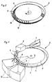
- the device according to the invention according to FIG. 1 has a conveying path formed by a drivable disk 2, to which a feed chute 1 is assigned for feeding in individual pieces 7 to be sorted, e.g. Bottles, cans and the like made of different materials.
- the disk 2 has a substantially flat or dome-shaped central region 3 which, in the exemplary embodiment shown, is surrounded by a region 4 which widens conically, which in turn is surrounded by an edge 5 which widens conically. This results in a circumferential channel which is provided for receiving the pieces 7 to be sorted.
- the feed chute 1 has a relatively slight inclination and is oriented tangentially to the groove formed by the area 4 and the edge 5 of the disk 2, so that the individual pieces 7 slide from the feed chute 1 into this groove.
- the individual pieces 7 are pressed against the inside of the edge 5 due to the centrifugal force caused by the rotation of the disc 2 and therefore do not change their position relative to the disc 2.
- the feed chute 1 is followed by a sensor device 6.
- This sensor device is equipped with sensors which mostly detect the reflectivity of the individual pieces 7 for infrared light and from these measurements detect the respective material from which the moving piece 7 is made.
- color sensors for essentially opaque pieces 7 operating according to the reflected light method and color sensors for transparent pieces 7 working according to the transmitted light method can also be provided in the sensor device 6 his.
- This sensor device 6 controls ejection devices 8, which are arranged downstream of the sensor device 6 in the direction of rotation of the disk 2, the ejection devices 8 being formed by blow-out nozzles. These blow-out nozzles are arranged below the disc 2 and directed obliquely outwards.
- the conical region 4 surrounding the central region 3 is provided with a large number of openings, or is formed from a wire mesh 9, expanded metal 10 or by rods 11 arranged at short intervals. As a result, correspondingly large areas are permeable to air.
- one of the ejection devices 8 is activated as soon as the relevant piece 7 has reached its area, the activation by the sensor device 6 depending on the speed of the disc 2 is controlled.
- a relatively large number of ejection devices 8 can be distributed over the circumference of the disk 2 be arranged, which also depends on the size of the pieces 7 to be sorted out.
- the ejection devices 8 are assigned to collecting container 12 in the embodiment according to FIG. 1, whereas in the embodiment according to FIGS. 3 and 4 the ejection devices 8 are assigned slides 14 which lead to conveyor devices, not shown.
- two receptacles 12 are arranged next to the disc, which collect the pieces 7 sorted according to material and color.
- a discharge device (not shown in FIG. 3) is arranged in the area of a transfer chute 13, which drops all pieces 7 onto the transfer chute that are not assigned to any of the throw-off devices arranged in the area of disc 2. These pieces 7 are then thrown off by the ejection devices in the area of the disc 2 ′ and fed to corresponding collecting containers 12.
- the ejection devices 8 are indicated by arrows.
- the ejection devices 8 can be formed by blowing nozzles, which are essentially aligned with the surface lines of the edge region of the disk 2, 2 '. Such an alignment of blowing nozzles with an essentially elongated outflow opening is particularly suitable if the rather larger parts are to be sorted, so that they can usually be acted upon by two adjacent blowing nozzles.
- FIG. 5a shows various embodiments of the edge region of the pane 2 or 2 '.
- the edge 5 can thus protrude directly from the flat region 3 of the pane 2, 2 '.
- the central region of the disk 2, 2 ' is domed upwards in the form of a dome, which is followed by a region 4 which widens conically downwards. This is surrounded by the edge 5, which widens conically upwards.
- This area 4 has a greater inclination to the horizontal than the dome-shaped area 3.
- the embodiment according to FIG. 5d differs from that according to FIG. 5c only in that area 4 has a lower inclination than in area 3.
- FIGS. 6 and 7 differs from that according to FIGS. 1 and 3 or 4 in that the ejection devices 8 are each formed by a pair of blowing nozzles 20, 21, both of which have an elongated outflow opening.
- One blowing nozzle 20 or its outflow opening is oriented essentially in the circumferential direction of the disc 2 and the second in the radial direction or in the direction of a generatrix of the frustoconical edge region of the disc 2. This results in an essentially T-shaped arrangement of the blowing nozzles 20, 21, the blowing nozzles 21 extending away from the blowing nozzles 20 towards the center of the disk 2, as can be clearly seen from FIGS. 6 and 6a.
- this T-shaped arrangement of the blowing nozzles results in a reliable ejection of objects of different shapes, whereby the objects to be ejected in a direction from by the blowing nozzles 21, which are inclined against the horizontal are blown away from the disc, which has an outwardly directed radial component.
- body 22 with an essentially round cross section, but also body 23 with a rather flat or oval cross section can be safely ejected over the edge 45 of the pane 2.
- the other structure of the disc 2 may be the same as that shown in FIGS. 1 and 3 and 4.
Abstract
Description
Die Erfindung bezieht sich auf ein Verfahren zum Sortieren von Abfällen gemäß dem Oberbegriff des Anspruches 1.The invention relates to a method for sorting waste according to the preamble of
Bei den bekannten derartigen Verfahren werden die vereinzelten Stücke auf einem im wesentlichen geraden Förderweg aufgegeben und im Bereich dieses Förderweges auf das verwendete Material und gegebenenfalls auch auf die Farbe hin untersucht und an diesen entsprechenden Abwurfstellen vom Förderweg entfernt.In the known methods of this type, the individual pieces are placed on an essentially straight conveying path and examined in the area of this conveying path for the material used and possibly also for the color and removed from the conveying path at these corresponding discharge points.
Dabei ergibt sich, insbesondere bei der Sortierung von Einwegverpackungen, die häufig in zwei Dimensionen runde Körper, wie Flaschen, Dosen, od. dgl. enthalten, das Problem, daß sich die Lage der einzelnen Stücke während des Transportweges häufig ändert. Letztlich kann es nach dem Aufgeben der Stücke zu einem "Springen" derselben kommen. Dies kann zu Fehlauswürfen der entsprechenden Stücke führen, wodurch die Qualität der Sortierung sehr erheblich leidet.The problem arises, in particular when sorting disposable packaging which often contains round bodies in two dimensions, such as bottles, cans or the like. The problem arises that the position of the individual pieces changes frequently during the transport route. Ultimately, after the pieces have been given up, they can "jump". This can lead to incorrect ejection of the corresponding pieces, which means that the quality of the sorting suffers considerably.
Eine weitestgehend sortenreine Trennung der Abfälle nach den verschiedenen Materialien ist aber insbesondere bei der Wiederverwertung von Kunststoffen für die Qualität des neuen Produktes von entscheidener Bedeutung.However, sorting the waste according to the different materials to the greatest possible extent is of crucial importance, especially when recycling plastics, for the quality of the new product.
Weiters wurde durch die US-PS 4 946 046 eine Einrichtung der eingangs erwähnten Art bekannt, bei der Vertiefungen in einem konvexen Förderweg vorgesehen sind, in denen die zu fördernden Teile aufgenommen werden können. Dadurch ergibt sich jedoch der Nachteil, daß nur Gegenstände gehalten werden können, deren Gestalt im wesentlichen jenen der Vertiefungen entspricht. Ein sicheres Halten von unterschiedlich geformten Gegenständen und Gegenständen stark unterschiedlicher Größe ist dagegen nicht möglich. Außerdem erfordert die Herstellung einer solchen bekannten Einrichtung einen sehr erheblichen Aufwand.Furthermore, a device of the type mentioned at the outset was known from US Pat. No. 4,946,046, in which recesses are provided in a convex conveying path, in which the parts to be conveyed can be accommodated. However, this results in the disadvantage that only objects can be held whose shape essentially corresponds to that of the depressions. However, it is not possible to securely hold objects of different shapes and objects of very different sizes. In addition, the production of such a known device requires a very considerable effort.
Ziel der Erfindung ist es, die angeführten Nachteile zu vermeiden und ein Verfahren der eingangs erwähnten Art vorzuschlagen, das eine sehr sortenreine Trennung der Abfälle nach Materialien und gegebenenfalls auch Farben ermöglicht.The aim of the invention is to avoid the disadvantages mentioned and to propose a method of the type mentioned at the outset which enables the waste to be sorted according to type by material and possibly also by color.
Erfindungsgemäß wird dies bei einem Verfahren der eingangs erwähnten Art durch die kennzeichnenden Merkmale des Anspruches 1 erreicht.According to the invention, this is achieved in a method of the type mentioned at the outset by the characterizing features of
Durch die vorgeschlagenen Maßnahmen ist sichergestellt, daß die einzelnen Stücke während des Weges zwischen der Aufgabestelle und der jeweiligen Abwurfstelle in Bezug auf den sich bewegenden Förderweg in ihrer Lage stabil zu dem sich bewegenden Förderweg gehalten werden. Dadurch wird erreicht, daß ein Stück, das aus einem bestimmten Material hergestellt ist, sicher an der dafür vorgesehenen Stelle abgeworfen wird.The proposed measures ensure that the individual pieces are kept stable in their position with respect to the moving conveyor path in relation to the moving conveyor path during the path between the feed point and the respective discharge point. This ensures that a piece that is made of a certain material is safely dropped at the intended location.
Ein weiteres Ziel der Erfindung ist es, eine Einrichtung zur Durchführung des erfindungsgemäßen Verfahrens vorzuschlagen.Another object of the invention is to propose a device for carrying out the method according to the invention.
Bei einer Einrichtung gemäß dem Oberbegriff des Anspruches 2 werden daher erfindungsgemäß die kennzeichnenden Merkmale des Anspruches 2 vorgeschlagen.In a device according to the preamble of
Durch diese Maßnahmen ergibt sich der Vorteil einer in konstruktiver Hinsicht sehr einfache Lösung, wobei durch die Ausbildung der Fördereinrichtung als Scheibe die Fliehkraft für die Fixierung der einzelnen Stücke sorgt.These measures result in the advantage of a solution which is very simple in terms of design, the centrifugal force ensuring the fixing of the individual pieces by the design of the conveyor device as a disk.
Durch die Merkmale des Anspruches 3 ergibt sich der Vorteil einer besonders sicheren Fixierung der Lage der einzelnen Stücke in Bezug auf die Scheibe.The features of
Durch die Merkmale des Anspruches 4 ergibt sich der Vorteil einer sehr einfachen Ausgestaltung der Abwurfeinrichtungen. Dabei erleichtert der sich kegelig nach oben zu erweiternde Rand der Scheibe das Auswerfen der einzelnen Stücke.The features of
Durch die Merkmale des Anspruches 5 ergibt sich der Vorteil, daß auch ungünstig geformte Körper, wie z.B. Flaschen mit großem Durchmesser und geringem Gewicht sicher ausgeworfen werden und dabei in eienr Richtung von der Scheibe wegeblasen werden, die eine radial nach außen gerichtete Komponente aufweist.The features of
Durch die Merkmale des Anspruches 6 ergibt sich eine erhebliche Einsparung an Druckluft. So ist es durch die vorgeschlagenen Maßnahmen möglich, kleinere Gegenstände durch Aktivierung lediglich einer Blasdüsenanordnung auszuwerfen und lediglich bei größeren Gegenständen zwei oder mehr Blasdüsenanordnungen, von denen jede durch ein Paar von Blasdüsen gebildet sein kann, zu aktivieren. Dadurch kann der Verbrauch an Druckluft wesentlich reduziert werden.The features of
Durch die Merkmale des Anspruches 7 ergibt sich der Vorteil, daß das Ausblasen der einzelnen Stücke durch den hohen Anteil an Durchbrechungen im Randbereich der Scheibe wesentlich erleichtert wird.The features of
Durch die Merkmale des Anspruches 8 ergibt sich der Vorteil, daß die einzelnen Stücke an den Rand geleitet werden.The features of
Die Erfindung wird nun anhand der Zeichnung näher erläutert. Dabei zeigen:
- Fig. 1
- schematisch eine erste Ausführungsform einer erfindungsgemäßen Einrichtung,
- Fig. 2
- schematisch Details der Scheibe,
- Fig. 3 und 4
- schematisch eine weitere Ausführungsform einer erfindungsgemäßen Einrichtung in Seitenansicht und Draufsicht,
- Fig. 5
- schematisch verschiedene Ausführungsformen des Randbereiches der Scheibe,
- Fig. 6
- eine Draufsicht auf eine weitere Ausführungsform einer erfindungsgemäßen Einrichtung,
- Fig. 6a
- ein Detail der Ausführungsform nach der Fig. 6,
- Fig. 7
- ein Schnitt durch die Einrichtung nach der Fig. 6 und
- Fig. 7a und 7b
- Details des Betriebs der Einrichtung nach den Fig. 6 und 7.
- Fig. 1
- schematically a first embodiment of a device according to the invention,
- Fig. 2
- schematic details of the disc,
- 3 and 4
- schematically a further embodiment of a device according to the invention in side view and plan view,
- Fig. 5
- schematically different embodiments of the edge area of the pane,
- Fig. 6
- a plan view of a further embodiment of a device according to the invention,
- Fig. 6a
- 6 shows a detail of the embodiment according to FIG. 6,
- Fig. 7
- a section through the device of FIGS. 6 and
- 7a and 7b
- Details of the operation of the device according to FIGS. 6 and 7.
Die erfindungsgemäße Einrichtung nach der Fig. 1 weist einen durch eine antreibbare Scheibe 2 gebildeten Förderweg auf, dem eine Aufgaberutsche 1 zur Aufgabe von vereinzelten zu sortierenden Stücken 7 zugeordnet ist, wie z.B. Flaschen, Dosen u.dgl. aus unterschiedlichsten Materialien auf.The device according to the invention according to FIG. 1 has a conveying path formed by a
Die Scheibe 2 weist einen im wesentlichen ebenen oder kalottenförmig nach oben gewölbten zentralen Bereich 3 auf, der beim dargestellten Ausführungsbeispiel von einem sich nach unten zu kegelförmig erweiternden Bereich 4 umgeben ist, der seinerseits von einem sich nach oben zu kegelförmig erweiternden Rand 5 umgeben ist. Dadurch ergibt sich eine umlaufende Rinne, die zur Aufnahme der zu sortierenden Stücke 7 vorgesehen ist.The
Die Aufgaberutsche 1 weist eine relativ geringe Neigung auf und ist tangential zur durch den Bereich 4 und den Rand 5 der Scheibe 2 gebildeten Rinne ausgerichtet, sodaß die einzelnen Stücke 7 von der Aufgaberutsche 1 in diese Rinne gleiten.The
Dabei werden die einzelnen Stücke 7 aufgrund der durch die Drehung der Scheibe 2 bedingten Fliehkraft an die Innenseite des Randes 5 gedrückt und ändern daher ihre Lage zur Scheibe 2 nicht.The
In Drehrichtung der Scheibe 2 ist der Aufgaberutsche 1 eine Sensoreinrichtung 6 nachgeordnet. Diese Sensoreinrichtung ist mit Sensoren ausgerüstet, die meist das Reflexionsvermögen der einzelenen Stücke 7 für infrarotes Licht erfassen und aus diesen Messungen das jeweilige Material aus dem das sich vorbeibewegende Stück 7 hergestellt ist erfassen.In the direction of rotation of the
Weiters können, wenn bei den verschiedenen Materialien, insbesondere Kunststofffen, auch eine Sortierung nach Farben gewünscht wird, auch nach dem Auflichtverfahren mit sichtbarem Licht arbeitende Farbsensoren für im wesentlichen undurchsichtige Stücke 7 und nach dem Durchlichtverfahren arbeitende Farbsensoren für transparente Stücke 7 in der Sensoreinrichtung 6 vorgesehen sein.Furthermore, if a sorting by color is also desired for the various materials, in particular plastic materials, color sensors for essentially
Diese Sensoreinrichtung 6 steuert Abwurfeinrichtungen 8, die der Sensoreinrichtung 6 in Drehrichtung der Scheibe 2 nachgeordnet sind, wobei die Abwurfeinrichtungen 8 durch Ausblasdüsen gebildet sind. Diese Ausblasdüsen sind unterhalb der Scheibe 2 angeordnet und schräg nach außen gerichtet. Dabei ist der den zentralen Bereich 3 umgebende kegelförmige Bereich 4 mit einer großen Zahl von Durchbrechungen versehen, oder ist aus einem Drahtgitter 9, Streckmetall 10 oder durch in geringen Abständen angeordnete Stäbe 11 gebildet. Dadurch sind entsprechend große Flächenanteile luftdurchlässig.This
Je nach dem von der Sensoranordnung 6 erkannten Material des betreffenden Stückes 7 und gegebenenfalls auch dessen Farbe innerhalb des selben Materials wird eine der Abwurfeinrichtungen 8 aktiviert, sobald das betreffende Stück 7 in dessen Bereich gelangt ist, wobei die Aktivierung durch die Sensoreinrichtung 6 in Abhängigkeit von der Drehzahl der Scheibe 2 gesteuert wird. Dabei können eine relativ große Zahl von Abwurfeinrichtungen 8 über den Umfang der Scheibe 2 verteilt angeordnet werden, wobei dies auch von der Größe der auszusortierenden Stücke 7 abhängt. Den Abwurfeinrichtungen 8 sind bei der Ausführungsform nach der Fig. 1 Auf fangbehälter 12 zugeordnet, wogegen bei der Ausführungsform nach den Fig. 3 und 4 den Abwurfeinrichtungen 8 Rutschen 14 zugeordnet sind, die zu nicht dargestellten Fördereinrichtungen führen.Depending on the material of the
Im Bereich der Abwurfeinrichtungen 8 sind neben der Scheibe 2 Auffangbehälter 12 angeordnet, die die nach Material und Farbe aussortierten Stücke 7 sortenrein aufnehmen.In the area of the
Bei der Ausführungsform nach der Fig. 3 und 4 sind zwei Scheiben 2, 2' vorgesehen. Dabei ist im Bereich einer Überleitungsrutsche 13 eine Abwurfeinrichtung (in Fig. 3 nicht dargestellt) angeordnet, die alle Stücke 7 auf die Überleitungsrutsche abwirft, die keinem der im Bereich der Scheibe 2 angeordneten Abwurffeinrichtungen zugeordnet sind. Diese Stücke 7 werden dann von den Abwurfeinrichtungen im Bereich der Scheibe 2' abgeworfen und entsprechenden Auffangbehältern 12 zugeführt.In the embodiment according to FIGS. 3 and 4, two
In der Fig. 4 sind die Abwurfeinrichtungen 8 durch Pfeile angedeutet. Dabei können die Abwurfeinrichtungen 8 durch Blasdüsen gebildet sein, die im wesentlichen nach den Mantellinien des Randbereiches der Scheibe 2, 2' ausgerichtet sind. Eine solche Ausrichtung von Blasdüsen mit im wesentlichen länglicher Ausströmöffnung eignet sich besonders, wenn die eher größere Teile zu sortieren sind, sodaß diese zumeist von zwei benachbarten Blasdüsen beaufschlagt werden können.4, the
Die Fig. 5a zeigt verschiedene Ausführungsformen des Randbereichs der Scheibe 2, bzw. 2'. So kann der Rand 5 direkt vom ebenen Bereich 3 der Scheibe 2, 2' aufragen.5a shows various embodiments of the edge region of the
Nach der Fig. 5b ragt ein sich nach oben zu erweiternder Rand 5 von einem sich kegelförmig nach unten zu erweiternden Bereich 4 auf, wobei die gesamte Scheibe 2, 2' kegelförmig ausgebildet sein kann.According to FIG. 5b, an
Nach der Fig. 5c ist der zentrale Bereich der Scheibe 2, 2' kalottenförmig nach oben gewölbt ausgebildet, an den sich ein sich kegelförmig nach unten zu erweiternder Bereich 4 anschließt. Dieser ist von dem sich kegelförmig nach oben zu erweiternden Rand 5 umgeben. Dabei weist dieser Bereich 4 eine stärkere Neigung gegen die Horizontale auf, als der kalottenförmige Bereich 3.According to FIG. 5c, the central region of the
Die Ausführung nach der Fig. 5d unterscheidet sich von jener nach der Fig. 5c nur dadurch, daß der Bereich 4 eine geringere Neigung aufweist als im Bereich 3.The embodiment according to FIG. 5d differs from that according to FIG. 5c only in that
Die Ausführungsform nach der Fig. 6 und 7 unterscheidet sich von jener nach den Fig. 1 und 3, bzw. 4 dadurch, daß die Abwurfeinrichtungen 8 durch je ein Paar von Blasdüsen 20, 21 gebildet sind, die beide eine längliche Ausströmöffnung aufweisen. Dabei ist eine Blasdüse 20, bzw. deren Ausströmöffnung im wesentlichen in Umfangsrichtung der Scheibe 2 ausgerichtet und die zweite in radialer Richtung, bzw. in Richtung einer Mantellinie des kegelstumpfförmigen Randbereiches der Scheibe 2. Dadurch ergibt sich eine im wesentlichen T-förmige Anordnung der Blasdüsen 20, 21, wobei sich die Blasdüsen 21 von den Blasdüsen 20 weg in Richtung zum Zentrum der Scheibe 2 hin erstrecken, wie deutlich aus den Fig. 6 und 6a zu ersehen ist.The embodiment according to FIGS. 6 and 7 differs from that according to FIGS. 1 and 3 or 4 in that the
Wie in den Fig. 7a und 7b schematisch dargestellt ist, ergibt sich durch diese T-förmige Anordnung der Blasdüsen ein sicheres Auswerfen auch unterschiedlich geformter Gegenstände, wobei durch die Blasdüsen 21, die gegen die Horizontale geneigt sind, die auszuwerfenden Gegenstände in einer Richtung von der Scheibe weggeblasen werden, die eine nach außen gerichtete radiale Komponente aufweist. Außerdem können dadurch nicht nur Körper 22 mit im wesentlichen rundem Querschnitt, sondern auch Körper 23 mit eher flachem oder ovalem Querschnitt sicher über den Rand 45 der Scheibe 2 abgeworfen werden.As is shown schematically in FIGS. 7a and 7b, this T-shaped arrangement of the blowing nozzles results in a reliable ejection of objects of different shapes, whereby the objects to be ejected in a direction from by the blowing
Der sonstige Aufbau der Scheibe 2 kann gleich jenem nach den Fig. 1 und 3 und 4 gestaltet sein.The other structure of the
Claims (8)
Applications Claiming Priority (4)
| Application Number | Priority Date | Filing Date | Title |
|---|---|---|---|
| AT18294A AT402165B (en) | 1994-02-01 | 1994-02-01 | Process and apparatus for sorting waste materials |
| AT33394A AT400413B (en) | 1994-02-18 | 1994-02-18 | Apparatus for sorting waste materials |
| AT333/94 | 1994-02-18 | ||
| AT182/94 | 1994-02-18 |
Publications (3)
| Publication Number | Publication Date |
|---|---|
| EP0669171A2 true EP0669171A2 (en) | 1995-08-30 |
| EP0669171A3 EP0669171A3 (en) | 1996-02-28 |
| EP0669171B1 EP0669171B1 (en) | 1999-04-07 |
Family
ID=25591762
Family Applications (1)
| Application Number | Title | Priority Date | Filing Date |
|---|---|---|---|
| EP95890020A Expired - Lifetime EP0669171B1 (en) | 1994-02-01 | 1995-01-30 | Device for sorting refuse |
Country Status (5)
| Country | Link |
|---|---|
| US (1) | US5590791A (en) |
| EP (1) | EP0669171B1 (en) |
| JP (1) | JPH0833871A (en) |
| AT (1) | ATE178512T1 (en) |
| DE (1) | DE59505545D1 (en) |
Cited By (8)
| Publication number | Priority date | Publication date | Assignee | Title |
|---|---|---|---|---|
| EP1402961A2 (en) * | 2002-09-26 | 2004-03-31 | Wincor Nixdorf International GmbH | Device for sorting waste |
| EP1688243A3 (en) * | 2005-02-03 | 2007-08-01 | Fette GmbH | Method and apparatus for sorting the tablets in a rotary press for tablets |
| CN105499155A (en) * | 2016-02-01 | 2016-04-20 | 先驱智能机械(深圳)有限公司 | Grasping and sorting method and sorting disc for objects |
| CN106115192A (en) * | 2016-08-02 | 2016-11-16 | 德阳精创机电股份有限公司 | A kind of centrifugal arranging machine |
| CN109499883A (en) * | 2018-11-27 | 2019-03-22 | 汤泓 | A kind of intelligent screening equipment |
| CN111167721A (en) * | 2020-01-08 | 2020-05-19 | 浙江辛巴达机器人科技有限公司 | Incessant sieving mechanism is used to bearing steel ball |
| CN113731848A (en) * | 2019-12-06 | 2021-12-03 | 浙江厚达智能科技股份有限公司 | Method for online removing defective bottled traditional Chinese medicine with substandard weight |
| CN113731847A (en) * | 2019-12-06 | 2021-12-03 | 浙江厚达智能科技股份有限公司 | Method for separately removing bottled Chinese medicines with super-defective products on line |
Families Citing this family (37)
| Publication number | Priority date | Publication date | Assignee | Title |
|---|---|---|---|---|
| AT401740B (en) * | 1994-12-27 | 1996-11-25 | Binder Co Ag | DEVICE FOR SEPARATING AREAS AND SPACELY BODIES |
| US6131744A (en) | 1997-05-02 | 2000-10-17 | Micro Beef Technologies, Inc. | System and method for recycling identification tags |
| AT2986U1 (en) | 1998-08-25 | 1999-08-25 | Binder Co Ag | LINEAR SORTING DEVICE |
| US6303925B1 (en) | 1999-02-24 | 2001-10-16 | Patricia Alaine Edmonds | Apparatus and method for distinguishing paper articles from plastic articles |
| JP3418787B2 (en) * | 1999-06-30 | 2003-06-23 | 株式会社日立製作所 | Waste treatment method and equipment |
| US7081217B2 (en) * | 2002-06-13 | 2006-07-25 | Dan Treleaven | Method for making plastic materials using recyclable plastics |
| US7351929B2 (en) * | 2002-08-12 | 2008-04-01 | Ecullet | Method of and apparatus for high speed, high quality, contaminant removal and color sorting of glass cullet |
| US7355140B1 (en) | 2002-08-12 | 2008-04-08 | Ecullet | Method of and apparatus for multi-stage sorting of glass cullets |
| US8436268B1 (en) | 2002-08-12 | 2013-05-07 | Ecullet | Method of and apparatus for type and color sorting of cullet |
| SE0300009D0 (en) * | 2003-01-03 | 2003-01-03 | Bomill Ab | Sorting Device |
| US7600642B2 (en) * | 2003-09-23 | 2009-10-13 | Monsanto Technology, Llc | High throughput automated seed analysis system |
| US7832143B2 (en) | 2004-08-26 | 2010-11-16 | Monsanto Technology Llc | High throughput methods for sampling seeds |
| WO2006026467A2 (en) * | 2004-08-26 | 2006-03-09 | Monsanto Technology Llc | Automated testing of seeds |
| US7703238B2 (en) | 2004-08-26 | 2010-04-27 | Monsanto Technology Llc | Methods of seed breeding using high throughput nondestructive seed sampling |
| US8028469B2 (en) | 2006-03-02 | 2011-10-04 | Monsanto Technology Llc | Automated high-throughput seed sampler and methods of sampling, testing and bulking seeds |
| US7998669B2 (en) | 2006-03-02 | 2011-08-16 | Monsanto Technology Llc | Automated contamination-free seed sampler and methods of sampling, testing and bulking seeds |
| US20070208455A1 (en) * | 2006-03-03 | 2007-09-06 | Machinefabriek Bollegraaf Appingedam B.V. | System and a method for sorting items out of waste material |
| CA2648213A1 (en) * | 2006-04-06 | 2007-10-18 | Monsanto Technology Llc | Method for multivariate analysis in predicting a trait of interest |
| JP4124242B2 (en) * | 2006-05-24 | 2008-07-23 | 株式会社村田製作所 | Work transfer device and electronic component transfer device |
| CN101772300B (en) | 2007-05-31 | 2013-07-24 | 孟山都技术有限公司 | Seed sorter |
| JP5140387B2 (en) * | 2007-11-16 | 2013-02-06 | 赤武エンジニアリング株式会社 | Particle detection / removal device |
| FI122025B (en) * | 2009-09-14 | 2011-07-29 | Maricap Oy | Procedure for sorting waste and waste sorting system |
| JP2011080384A (en) * | 2009-10-05 | 2011-04-21 | Otics Corp | Vehicle engine |
| CN104826820B (en) * | 2015-05-19 | 2017-10-31 | 东北大学 | Rotating disk rejecting mechanism for pcb board automatic letter sorting machine |
| US9851719B2 (en) * | 2016-05-31 | 2017-12-26 | Caterpillar Inc. | System and method for executing a project plan at worksite |
| US9999906B2 (en) * | 2016-06-29 | 2018-06-19 | John Bean Technologies Corporation | Sorter |
| BR112019001728B1 (en) * | 2016-07-29 | 2022-06-21 | 9754741 Canada Ltd | Method for the singularization of particles |
| US10406564B1 (en) | 2017-12-14 | 2019-09-10 | Asmaa F. F. N. Al-Ateeq | Sorting waste receptacle |
| CN112135784B (en) * | 2018-04-13 | 2023-07-18 | 9754741加拿大有限公司 | Separating and orienting objects for feeding |
| CN110302964A (en) * | 2019-08-08 | 2019-10-08 | 彭广雷 | A kind of centrifugal walnut sorting machine |
| US11651334B1 (en) | 2019-11-25 | 2023-05-16 | State Farm Mutual Automobile Insurance Company | Systems and methods for enhancing waste disposal and energy efficiency using sensor and alternative power technologies |
| CN211070897U (en) * | 2019-11-29 | 2020-07-24 | 北京旷视机器人技术有限公司 | Sorting equipment |
| CN112090792B (en) * | 2020-08-15 | 2022-07-12 | 安徽省羽乐体育用品有限公司 | Badminton processing is with feather pole eccentricity screening device |
| CN113262990B (en) * | 2021-07-01 | 2023-04-28 | 广东弓叶科技有限公司 | Intelligent blowing sorting system and sorting device |
| CN113560204A (en) * | 2021-07-26 | 2021-10-29 | 嵊州市新起点焊接科技有限公司 | Detection device for copper pipe of double-cylinder air inlet pipe assembly of air conditioner compressor |
| KR102572962B1 (en) * | 2021-11-09 | 2023-09-01 | (주)에스피성보 | Waste seperating device |
| CN114210572B (en) * | 2021-12-14 | 2023-03-21 | 东北大学秦皇岛分校 | E-commerce logistics sorting guider |
Citations (3)
| Publication number | Priority date | Publication date | Assignee | Title |
|---|---|---|---|---|
| DE3346129A1 (en) * | 1983-12-21 | 1985-07-11 | Fa. Hermann Heye, 3063 Obernkirchen | Method and device for sorting refuse containing used glass |
| EP0461616A2 (en) * | 1990-06-15 | 1991-12-18 | Hubertus Exner | Method and device for sorting waste glass |
| WO1992002025A1 (en) * | 1990-07-20 | 1992-02-06 | Siemens Aktiengesellschaft | Process and device for handling liquid radioactive waste |
Family Cites Families (3)
| Publication number | Priority date | Publication date | Assignee | Title |
|---|---|---|---|---|
| US3517807A (en) * | 1968-07-11 | 1970-06-30 | Neil Van Gaalen | Apparatus for sorting fish eggs |
| US4946046A (en) * | 1988-05-09 | 1990-08-07 | Sheldon Affleck | Apparatus for sorting seeds according to color |
| US5443164A (en) * | 1993-08-10 | 1995-08-22 | Simco/Ramic Corporation | Plastic container sorting system and method |
-
1995
- 1995-01-27 JP JP7011931A patent/JPH0833871A/en not_active Withdrawn
- 1995-01-30 DE DE59505545T patent/DE59505545D1/en not_active Expired - Fee Related
- 1995-01-30 AT AT95890020T patent/ATE178512T1/en not_active IP Right Cessation
- 1995-01-30 EP EP95890020A patent/EP0669171B1/en not_active Expired - Lifetime
- 1995-02-01 US US08/382,243 patent/US5590791A/en not_active Expired - Fee Related
Patent Citations (3)
| Publication number | Priority date | Publication date | Assignee | Title |
|---|---|---|---|---|
| DE3346129A1 (en) * | 1983-12-21 | 1985-07-11 | Fa. Hermann Heye, 3063 Obernkirchen | Method and device for sorting refuse containing used glass |
| EP0461616A2 (en) * | 1990-06-15 | 1991-12-18 | Hubertus Exner | Method and device for sorting waste glass |
| WO1992002025A1 (en) * | 1990-07-20 | 1992-02-06 | Siemens Aktiengesellschaft | Process and device for handling liquid radioactive waste |
Cited By (12)
| Publication number | Priority date | Publication date | Assignee | Title |
|---|---|---|---|---|
| EP1402961A2 (en) * | 2002-09-26 | 2004-03-31 | Wincor Nixdorf International GmbH | Device for sorting waste |
| DE10245167A1 (en) * | 2002-09-26 | 2004-04-08 | Prokent Ag I.Ins. | Device for sorting waste |
| DE10245167B4 (en) * | 2002-09-26 | 2004-10-21 | Wincor Nixdorf International Gmbh | Device for sorting waste |
| EP1402961A3 (en) * | 2002-09-26 | 2005-07-06 | Wincor Nixdorf International GmbH | Device for sorting waste |
| EP1688243A3 (en) * | 2005-02-03 | 2007-08-01 | Fette GmbH | Method and apparatus for sorting the tablets in a rotary press for tablets |
| CN105499155A (en) * | 2016-02-01 | 2016-04-20 | 先驱智能机械(深圳)有限公司 | Grasping and sorting method and sorting disc for objects |
| CN106115192A (en) * | 2016-08-02 | 2016-11-16 | 德阳精创机电股份有限公司 | A kind of centrifugal arranging machine |
| CN106115192B (en) * | 2016-08-02 | 2018-07-31 | 德阳精创机电股份有限公司 | A kind of centrifugation arranging machine |
| CN109499883A (en) * | 2018-11-27 | 2019-03-22 | 汤泓 | A kind of intelligent screening equipment |
| CN113731848A (en) * | 2019-12-06 | 2021-12-03 | 浙江厚达智能科技股份有限公司 | Method for online removing defective bottled traditional Chinese medicine with substandard weight |
| CN113731847A (en) * | 2019-12-06 | 2021-12-03 | 浙江厚达智能科技股份有限公司 | Method for separately removing bottled Chinese medicines with super-defective products on line |
| CN111167721A (en) * | 2020-01-08 | 2020-05-19 | 浙江辛巴达机器人科技有限公司 | Incessant sieving mechanism is used to bearing steel ball |
Also Published As
| Publication number | Publication date |
|---|---|
| US5590791A (en) | 1997-01-07 |
| DE59505545D1 (en) | 1999-05-12 |
| EP0669171B1 (en) | 1999-04-07 |
| EP0669171A3 (en) | 1996-02-28 |
| JPH0833871A (en) | 1996-02-06 |
| ATE178512T1 (en) | 1999-04-15 |
Similar Documents
| Publication | Publication Date | Title |
|---|---|---|
| EP0669171A2 (en) | Device for sorting refuse | |
| EP1253981B1 (en) | Method for sorting out metal fractions from a stream of bulk material | |
| EP0982083B1 (en) | Linear sorting apparatus | |
| DE2619153C2 (en) | Device for aligning and feeding closure caps or the like | |
| EP2221261B1 (en) | Device for conveying preforms | |
| EP0154599A1 (en) | Sorting plant for extracting valuable products from household refuse, industrial refuse, bulky refuse, dry refuse, and for problematic and dangerous material | |
| DE102009016593A1 (en) | Device for transporting preforms of glass machine for manufacturing plastic containers, has conveyor for preforms, where transport of preforms is carried out by conveyor into subsequent treatment machine | |
| EP0636322B1 (en) | Feeding device for producing an uniform layer | |
| EP3476779B1 (en) | Apparatus and method for sorting and separating closure caps | |
| DE3614400C1 (en) | Method and device for controlling a color sorting machine | |
| EP0897762B1 (en) | Device for sorting raw, pre-treated or recycled bulk material | |
| DE3828067C2 (en) | ||
| EP0718219A2 (en) | Singulating device | |
| DE4019203A1 (en) | METHOD AND DEVICE FOR SORTING OLD GLASS | |
| EP0342389A2 (en) | Method and device for sorting old glass | |
| DE19545240A1 (en) | Sorting machine achieving more precise recognition and separation of e.g. mixed plastics fractions | |
| AT402165B (en) | Process and apparatus for sorting waste materials | |
| DE2754189A1 (en) | Bottle cap sorting machine - has rotating plate with control passages and supply conveyor and removal channel with outlet | |
| AT401740B (en) | DEVICE FOR SEPARATING AREAS AND SPACELY BODIES | |
| DE19700512B4 (en) | Sorting and feeding machine | |
| AT400413B (en) | Apparatus for sorting waste materials | |
| DE4302736C2 (en) | Method and device for sorting plastic containers | |
| EP0565038A1 (en) | Method and device for sorting refuse | |
| DE4316422C1 (en) | Process and device for screening waste mixtures | |
| EP3015003B1 (en) | Sorting device for long articles, especially for cigarettes |
Legal Events
| Date | Code | Title | Description |
|---|---|---|---|
| PUAI | Public reference made under article 153(3) epc to a published international application that has entered the european phase |
Free format text: ORIGINAL CODE: 0009012 |
|
| AK | Designated contracting states |
Kind code of ref document: A2 Designated state(s): AT BE CH DE FR GB IT LI NL SE |
|
| RAX | Requested extension states of the european patent have changed |
Free format text: SI PAYMENT 950228 |
|
| PUAL | Search report despatched |
Free format text: ORIGINAL CODE: 0009013 |
|
| AK | Designated contracting states |
Kind code of ref document: A3 Designated state(s): AT BE CH DE FR GB IT LI NL SE |
|
| AX | Request for extension of the european patent |
Free format text: SI PAYMENT 950228 |
|
| 17P | Request for examination filed |
Effective date: 19960219 |
|
| EL | Fr: translation of claims filed | ||
| EL | Fr: translation of claims filed | ||
| 17Q | First examination report despatched |
Effective date: 19980514 |
|
| GRAG | Despatch of communication of intention to grant |
Free format text: ORIGINAL CODE: EPIDOS AGRA |
|
| GRAG | Despatch of communication of intention to grant |
Free format text: ORIGINAL CODE: EPIDOS AGRA |
|
| GRAH | Despatch of communication of intention to grant a patent |
Free format text: ORIGINAL CODE: EPIDOS IGRA |
|
| GRAH | Despatch of communication of intention to grant a patent |
Free format text: ORIGINAL CODE: EPIDOS IGRA |
|
| GRAA | (expected) grant |
Free format text: ORIGINAL CODE: 0009210 |
|
| AK | Designated contracting states |
Kind code of ref document: B1 Designated state(s): AT BE CH DE FR GB IT LI NL SE |
|
| AX | Request for extension of the european patent |
Free format text: SI PAYMENT 950228 |
|
| REF | Corresponds to: |
Ref document number: 178512 Country of ref document: AT Date of ref document: 19990415 Kind code of ref document: T |
|
| ITF | It: translation for a ep patent filed |
Owner name: JACOBACCI & PERANI S.P.A. |
|
| REG | Reference to a national code |
Ref country code: CH Ref legal event code: EP |
|
| REG | Reference to a national code |
Ref country code: CH Ref legal event code: NV Representative=s name: PATENTANWAELTE SCHAAD, BALASS, MENZL & PARTNER AG |
|
| REF | Corresponds to: |
Ref document number: 59505545 Country of ref document: DE Date of ref document: 19990512 |
|
| GBT | Gb: translation of ep patent filed (gb section 77(6)(a)/1977) |
Effective date: 19990504 |
|
| ET | Fr: translation filed | ||
| PG25 | Lapsed in a contracting state [announced via postgrant information from national office to epo] |
Ref country code: GB Free format text: LAPSE BECAUSE OF NON-PAYMENT OF DUE FEES Effective date: 20000130 Ref country code: AT Free format text: LAPSE BECAUSE OF NON-PAYMENT OF DUE FEES Effective date: 20000130 |
|
| PG25 | Lapsed in a contracting state [announced via postgrant information from national office to epo] |
Ref country code: SE Free format text: LAPSE BECAUSE OF NON-PAYMENT OF DUE FEES Effective date: 20000131 Ref country code: LI Free format text: LAPSE BECAUSE OF NON-PAYMENT OF DUE FEES Effective date: 20000131 Ref country code: CH Free format text: LAPSE BECAUSE OF NON-PAYMENT OF DUE FEES Effective date: 20000131 Ref country code: BE Free format text: LAPSE BECAUSE OF NON-PAYMENT OF DUE FEES Effective date: 20000131 |
|
| PLBE | No opposition filed within time limit |
Free format text: ORIGINAL CODE: 0009261 |
|
| STAA | Information on the status of an ep patent application or granted ep patent |
Free format text: STATUS: NO OPPOSITION FILED WITHIN TIME LIMIT |
|
| 26N | No opposition filed | ||
| BERE | Be: lapsed |
Owner name: BINDER & CO. A.G. Effective date: 20000131 |
|
| PG25 | Lapsed in a contracting state [announced via postgrant information from national office to epo] |
Ref country code: NL Free format text: LAPSE BECAUSE OF NON-PAYMENT OF DUE FEES Effective date: 20000801 |
|
| EUG | Se: european patent has lapsed |
Ref document number: 95890020.1 |
|
| REG | Reference to a national code |
Ref country code: CH Ref legal event code: PL |
|
| GBPC | Gb: european patent ceased through non-payment of renewal fee |
Effective date: 20000130 |
|
| NLV4 | Nl: lapsed or anulled due to non-payment of the annual fee |
Effective date: 20000801 |
|
| PG25 | Lapsed in a contracting state [announced via postgrant information from national office to epo] |
Ref country code: DE Free format text: LAPSE BECAUSE OF NON-PAYMENT OF DUE FEES Effective date: 20001101 |
|
| PG25 | Lapsed in a contracting state [announced via postgrant information from national office to epo] |
Ref country code: FR Free format text: LAPSE BECAUSE OF NON-PAYMENT OF DUE FEES Effective date: 20010531 |
|
| REG | Reference to a national code |
Ref country code: FR Ref legal event code: ST |
|
| PG25 | Lapsed in a contracting state [announced via postgrant information from national office to epo] |
Ref country code: IT Free format text: LAPSE BECAUSE OF NON-PAYMENT OF DUE FEES Effective date: 20050130 |
|
| PG25 | Lapsed in a contracting state [announced via postgrant information from national office to epo] |
Ref country code: FR Free format text: LAPSE BECAUSE OF NON-PAYMENT OF DUE FEES Effective date: 20000131 |