EP0669169A2 - Dispositif piézoélectrique de réception des ondes - Google Patents
Dispositif piézoélectrique de réception des ondes Download PDFInfo
- Publication number
- EP0669169A2 EP0669169A2 EP95300269A EP95300269A EP0669169A2 EP 0669169 A2 EP0669169 A2 EP 0669169A2 EP 95300269 A EP95300269 A EP 95300269A EP 95300269 A EP95300269 A EP 95300269A EP 0669169 A2 EP0669169 A2 EP 0669169A2
- Authority
- EP
- European Patent Office
- Prior art keywords
- piezoelectric
- piezoelectric body
- tubular
- piezoelectric element
- piezoelectric device
- Prior art date
- Legal status (The legal status is an assumption and is not a legal conclusion. Google has not performed a legal analysis and makes no representation as to the accuracy of the status listed.)
- Withdrawn
Links
- 239000011347 resin Substances 0.000 claims description 10
- 229920005989 resin Polymers 0.000 claims description 10
- 239000000919 ceramic Substances 0.000 claims description 4
- 239000006260 foam Substances 0.000 claims description 4
- 239000007788 liquid Substances 0.000 claims description 4
- 238000004804 winding Methods 0.000 claims description 3
- 230000001902 propagating effect Effects 0.000 claims 2
- 230000002706 hydrostatic effect Effects 0.000 abstract description 3
- 230000000052 comparative effect Effects 0.000 description 15
- 230000009471 action Effects 0.000 description 14
- 230000010287 polarization Effects 0.000 description 11
- 239000000463 material Substances 0.000 description 10
- BQCIDUSAKPWEOX-UHFFFAOYSA-N 1,1-Difluoroethene Chemical compound FC(F)=C BQCIDUSAKPWEOX-UHFFFAOYSA-N 0.000 description 8
- 239000000853 adhesive Substances 0.000 description 7
- 230000001070 adhesive effect Effects 0.000 description 7
- 238000007493 shaping process Methods 0.000 description 6
- 229920001577 copolymer Polymers 0.000 description 5
- 229920001971 elastomer Polymers 0.000 description 5
- 239000000806 elastomer Substances 0.000 description 5
- MIZLGWKEZAPEFJ-UHFFFAOYSA-N 1,1,2-trifluoroethene Chemical group FC=C(F)F MIZLGWKEZAPEFJ-UHFFFAOYSA-N 0.000 description 4
- 230000006835 compression Effects 0.000 description 4
- 238000007906 compression Methods 0.000 description 4
- 230000035945 sensitivity Effects 0.000 description 4
- 238000002425 crystallisation Methods 0.000 description 3
- 230000008025 crystallization Effects 0.000 description 3
- 238000001514 detection method Methods 0.000 description 3
- 238000006073 displacement reaction Methods 0.000 description 3
- 230000000694 effects Effects 0.000 description 3
- 230000005684 electric field Effects 0.000 description 3
- 239000007789 gas Substances 0.000 description 3
- 239000010410 layer Substances 0.000 description 3
- 230000010355 oscillation Effects 0.000 description 3
- 230000002093 peripheral effect Effects 0.000 description 3
- CSCPPACGZOOCGX-UHFFFAOYSA-N Acetone Chemical compound CC(C)=O CSCPPACGZOOCGX-UHFFFAOYSA-N 0.000 description 2
- 239000004925 Acrylic resin Substances 0.000 description 2
- 229920000178 Acrylic resin Polymers 0.000 description 2
- PXHVJJICTQNCMI-UHFFFAOYSA-N Nickel Chemical compound [Ni] PXHVJJICTQNCMI-UHFFFAOYSA-N 0.000 description 2
- 230000002411 adverse Effects 0.000 description 2
- 230000003321 amplification Effects 0.000 description 2
- 230000008859 change Effects 0.000 description 2
- 238000010438 heat treatment Methods 0.000 description 2
- 229920001519 homopolymer Polymers 0.000 description 2
- 238000005259 measurement Methods 0.000 description 2
- 238000003199 nucleic acid amplification method Methods 0.000 description 2
- 239000003973 paint Substances 0.000 description 2
- 239000004033 plastic Substances 0.000 description 2
- 229920003023 plastic Polymers 0.000 description 2
- 230000000644 propagated effect Effects 0.000 description 2
- 230000004044 response Effects 0.000 description 2
- BFKJFAAPBSQJPD-UHFFFAOYSA-N tetrafluoroethene Chemical group FC(F)=C(F)F BFKJFAAPBSQJPD-UHFFFAOYSA-N 0.000 description 2
- IJGRMHOSHXDMSA-UHFFFAOYSA-N Atomic nitrogen Chemical compound N#N IJGRMHOSHXDMSA-UHFFFAOYSA-N 0.000 description 1
- 229910000906 Bronze Inorganic materials 0.000 description 1
- 102100025840 Coiled-coil domain-containing protein 86 Human genes 0.000 description 1
- 101000932708 Homo sapiens Coiled-coil domain-containing protein 86 Proteins 0.000 description 1
- OAICVXFJPJFONN-UHFFFAOYSA-N Phosphorus Chemical compound [P] OAICVXFJPJFONN-UHFFFAOYSA-N 0.000 description 1
- 229920006311 Urethane elastomer Polymers 0.000 description 1
- BZHJMEDXRYGGRV-UHFFFAOYSA-N Vinyl chloride Chemical compound ClC=C BZHJMEDXRYGGRV-UHFFFAOYSA-N 0.000 description 1
- 229910052782 aluminium Inorganic materials 0.000 description 1
- XAGFODPZIPBFFR-UHFFFAOYSA-N aluminium Chemical compound [Al] XAGFODPZIPBFFR-UHFFFAOYSA-N 0.000 description 1
- 238000005452 bending Methods 0.000 description 1
- 239000010974 bronze Substances 0.000 description 1
- 239000011248 coating agent Substances 0.000 description 1
- 238000000576 coating method Methods 0.000 description 1
- 230000008094 contradictory effect Effects 0.000 description 1
- KUNSUQLRTQLHQQ-UHFFFAOYSA-N copper tin Chemical compound [Cu].[Sn] KUNSUQLRTQLHQQ-UHFFFAOYSA-N 0.000 description 1
- 230000003467 diminishing effect Effects 0.000 description 1
- 229910001873 dinitrogen Inorganic materials 0.000 description 1
- 239000003822 epoxy resin Substances 0.000 description 1
- 230000001747 exhibiting effect Effects 0.000 description 1
- 238000001125 extrusion Methods 0.000 description 1
- 239000011888 foil Substances 0.000 description 1
- LELOWRISYMNNSU-UHFFFAOYSA-N hydrogen cyanide Chemical compound N#C LELOWRISYMNNSU-UHFFFAOYSA-N 0.000 description 1
- 229910052751 metal Inorganic materials 0.000 description 1
- 239000002184 metal Substances 0.000 description 1
- 229910052759 nickel Inorganic materials 0.000 description 1
- 229920000647 polyepoxide Polymers 0.000 description 1
- 229920000642 polymer Polymers 0.000 description 1
- 230000002829 reductive effect Effects 0.000 description 1
- 230000002441 reversible effect Effects 0.000 description 1
- 238000007789 sealing Methods 0.000 description 1
- 229920002545 silicone oil Polymers 0.000 description 1
- 239000002356 single layer Substances 0.000 description 1
- 239000007787 solid Substances 0.000 description 1
- 230000003068 static effect Effects 0.000 description 1
- 239000002344 surface layer Substances 0.000 description 1
- 230000008961 swelling Effects 0.000 description 1
- XLYOFNOQVPJJNP-UHFFFAOYSA-N water Substances O XLYOFNOQVPJJNP-UHFFFAOYSA-N 0.000 description 1
Images


Classifications
-
- B—PERFORMING OPERATIONS; TRANSPORTING
- B06—GENERATING OR TRANSMITTING MECHANICAL VIBRATIONS IN GENERAL
- B06B—METHODS OR APPARATUS FOR GENERATING OR TRANSMITTING MECHANICAL VIBRATIONS OF INFRASONIC, SONIC, OR ULTRASONIC FREQUENCY, e.g. FOR PERFORMING MECHANICAL WORK IN GENERAL
- B06B1/00—Methods or apparatus for generating mechanical vibrations of infrasonic, sonic, or ultrasonic frequency
- B06B1/02—Methods or apparatus for generating mechanical vibrations of infrasonic, sonic, or ultrasonic frequency making use of electrical energy
- B06B1/06—Methods or apparatus for generating mechanical vibrations of infrasonic, sonic, or ultrasonic frequency making use of electrical energy operating with piezoelectric effect or with electrostriction
- B06B1/0644—Methods or apparatus for generating mechanical vibrations of infrasonic, sonic, or ultrasonic frequency making use of electrical energy operating with piezoelectric effect or with electrostriction using a single piezoelectric element
- B06B1/0655—Methods or apparatus for generating mechanical vibrations of infrasonic, sonic, or ultrasonic frequency making use of electrical energy operating with piezoelectric effect or with electrostriction using a single piezoelectric element of cylindrical shape
-
- H—ELECTRICITY
- H04—ELECTRIC COMMUNICATION TECHNIQUE
- H04R—LOUDSPEAKERS, MICROPHONES, GRAMOPHONE PICK-UPS OR LIKE ACOUSTIC ELECTROMECHANICAL TRANSDUCERS; DEAF-AID SETS; PUBLIC ADDRESS SYSTEMS
- H04R17/00—Piezoelectric transducers; Electrostrictive transducers
Definitions
- the present invention relates to a wave-receiving (or passive) piezoelectric device having an enhanced sensitivity of receiving an acoustic wave.
- wave-receiving piezoelectric devices inclusive of a microphone which is generally placed in a gaseous medium such as air or a gas so as to receive an acoustic wave propagated through the gaseous medium, and a hydrophone which is generally placed in a liquid medium such as water or other liquids so as to receive an acoustic wave propagated through the liquid medium.
- the acoustic wave-receiving sensitivity of such a piezoelectric device may be expressed in terms of a hydrostatic piezoelectric constant d h in case where the device has a sufficiently smaller size than the wavelength of the acoustic wave, and is of course better if the d h constant is larger.
- the polarization direction is frequently taken in the thickness direction in view of the facility of polarization treatment, and the component (d33) in the thickness direction and the components (d31 and d32) in the two directions perpendicular thereto have mutually opposite signs, i.e., mutually contradictory functions, in many cases.
- a piezoelectric device principally utilizing a piezoelectric constant d33 in the thickness direction of a sheet-form piezoelectric body as described above, particularly one having a structure comprising a sheet-form piezoelectric body having electrodes on both surfaces thereof and a pair of rigid members having a larger area and sandwiching the both surfaces of the sheet-form piezoelectric body via the electrodes, it is necessary to narrow the electrode area in order to obtain an increased pressure-amplifying ratio by using rigid members having a definite area. As a result, it becomes difficult to take out lead wires from the electrodes, and the capacitance of the piezoelectric device becomes smaller, thus resulting in an increased internal impedance.
- a detection circuit for taking out a voltage output from such a device is required of an input impedance which is still larger than the internal impedance of the device. Accordingly, the detection circuit suffers from disadvantages such that it is liable to be affected by noises of, e.g., electromagnetic wave, its performances are liable to be unstable, it cannot use long lead wires, and it should be constituted while paying special measures against such problems.
- An object of the present invention is to realize a wave-receiving piezoelectric device having a higher sensitivity from a given piezoelectric material or body, while obviating difficulties in device structure including a detection circuit encountered in a piezoelectric device utilizing a d33 constant of a sheet-form piezoelectric body as described above.
- a wave-receiving piezoelectric device comprising: a tubular piezoelectric element including a piezoelectric body which has an outer surface and an inner surface constituting principal two surfaces, two opposite sides almost perpendicular to the two surfaces, a sectional shape corresponding to the thickness of a closed loop or a vortex, and an overall shape of roughly a tube, the piezoelectric body being polarized in its thickness direction; and electrodes respectively disposed on the two surfaces; and a pair of rigid members sandwiching the piezoelectric body at the two opposite sides; so that an acoustic pressure received by outer surfaces of the rigid members is concentratively applied as a stress for changing a distance between said two opposite sides of the piezoelectric body.
- the pair of rigid members are displaceable in response to the acoustic pressure without hindering the displacement of the tubular piezoelectric body in the axial direction thereof, and the rigid members are disposed so as to substantially interrupt the acoustic pressure from acting on at least one of the inner and outer surfaces of the tubular piezoelectric body. It is particularly preferred that the outwardly projecting portions not used for sandwiching the tubular piezoelectric body of the pair of rigid members are caused to define an airtight space with their inner surfaces.
- the outer surface (effective action area) of a rigid member which is effective to receive an acoustic pressure to be concentrated as a stress for causing a deformation of the piezoelectric body in its surface extension direction, i.e., an axial direction is not an outer surface area per se in an ordinary sense but is the projection area of the rigid member onto a plane perpendicular to the pressing direction in which the rigid member presses the piezoelectric body and more exactly a difference obtained by subtracting, from the projection area, the area of an inner surface opposite to the outer surface of the rigid member (more exactly, the projection area thereof onto a plane perpendicular to the pressing direction, similarly as above) in case where the acoustic pressure also acts on the inner surface.
- the above-mentioned "plane perpendicular to a direction of pressing the piezoelectric body” is generally regarded as a plane parallel to the sides of the piezoelectric body, i.e., a plane perpendicular to the axis of the tubular piezoelectric body.
- the acoustic wave referred to herein should be construed as a wave of pressure oscillation and not limited to the audio frequency wave. More exactly, the acoustic wave used herein means a wave of pressure oscillation having a wavelength which is comparable to or larger than the length of the rigid member.
- the acoustic pressure is the pressure of the oscillation mentioned above.
- the length in axial direction of the tubular piezoelectric body independently of a pressure-amplifying ratio determined by a ratio of the effective action area of the rigid member/the side area of the tubular piezoelectric body, it is possible to change the electrode area of the device, whereby the internal impedance of the device can be arbitrarily set.
- the interruption of an acoustic pressure from acting onto the inner surface of the rigid member performed for pressure amplification by the rigid member also has an effect of interrupting the contribution of a component in thickness direction (d33 component) which, in many cases, has a function adverse to the effective components (d31 and d32 components of a piezoelectric body polarized in the thickness direction) perpendicular to the polarization directions of the piezoelectric body among the components of the d h constant, i.e., an effect of shielding the action of the acoustic pressure onto the piezoelectric body in the thickness direction. This also contributes to an apparent increase in d h constant.
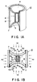
- Figures 1A and 1B are a partially cut-out perspective view and a front sectional view, respectively, of an embodiment of the wave-receiving piezoelectric device of the invention.
- Figures 2A and 2B are an enlarged plan view and an enlarged front sectional view, respectively, of a tubular piezoelectric element contained in the embodiment shown in Figures 1A and 1B.
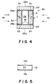
- Figures 3 and 4 are respectively a front sectional view of another embodiment of the wave-receiving piezoelectric device of the invention.
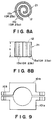
- Figure 5 is a schematic sectional view of an example of a sheet-form polymeric piezoelectric element before shaping into a tubular piezoelectric element.
- Figures 6A and 6B are a plan view and a front view, respectively, of a tubular piezoelectric element shaped from the sheet-form piezoelectric element shown in Figure 5.
- Figure 7 is a schematic sectional view of another example of a sheet-form polymeric piezoelectric element before shaping into a tubular piezoelectric element.
- Figures 8A and 8B are a plan view and a front view, respectively, of a tubular vortex-form piezoelectric element shaped from the sheet-form piezoelectric element shown in Figure 5 or 7.
- Figure 9 is a sectional view of a mold used for shaping into a tubular piezoelectric element having a vortex section in an Example.
- FIG 1A is a partially cut-out perspective view of an embodiment of the wave-receiving piezoelectric device (hereinafter simply called “piezoelectric device”) according to the present invention
- Figure 1B is a corresponding front sectional view.
- Figures 2A and 2B are an enlarged plan view and an enlarged front sectional view, respectively, of a tubular piezoelectric element contained in the embodiment.
- a piezoelectric device 10 comprises a tubular piezoelectric element 1 which in turn comprises a piezoelectric body 2.
- the piezoelectric body 2 has an outer surface 2a and an inner surface 2b constituting two principal surfaces sandwiching a thickness t , also has mutually opposite two sides 2c and 2d (shown as upper and lower faces in the figures) perpendicular to the two surfaces 2a and 2b, has a sectional shape corresponding to the thickness of a closed loop (an annular shape in this embodiment), has an overall shape of roughly a tube, and has a polarization p in the thickness direction.
- the tubular piezoelectric element 1 further comprises an electrode 3a and an electrode 3b respectively formed on the two surfaces 2a and 2b of the piezoelectric body 2.
- the piezoelectric device 10 further includes a pair of rigid members 4 and 5 sandwiching the tubular piezoelectric body 2 at its opposite two sides 2c and 2d and having a larger area than the sides, so that an acoustic pressure sp acting on the pair of rigid members 4 and 5 is concentratively applied as a stress for changing (reducing) the distance between the opposite two sides 2c and 2d of the tubular piezoelectric body 2.
- the tubular piezoelectric body is sandwiched at its opposite two sides 2c and 2d with the pair of rigid members 4 and 5 each having the shape of a bowl having a horizontal shape of a circle.
- the rigid members 4 and 5 are respectively disposed to have curved outer surfaces 4a and 5a and outwardly extending portions 4b and 5b not participating in sandwiching the piezoelectric body 2.
- the rigid members 4 and 5 are further formed to have flat pressing faces (bottom faces) 4c and 5c so that the faces 4c and 5c are uniformly abutted and bonded, if necessary, to the flat sides 2c and 2d of the tubular piezoelectric body 2.
- the pair of rigid members 4 and 5 sandwiching the tubular piezoelectric body 2 (and accordingly the tubular piezoelectric element 1 including it) is accommodated within a rigid cylinder 6 so that gaps between their sides 4d and 5d and the cylinder 6 are sealed with an elastomer resin 7.
- the pair of rigid members 4 and 5 receive from upper and lower directions an acoustic pressure sp corresponding to their effective action area (i.e., not that of the curving outer surfaces 4a and 5a per se but the area of projection of the outer surfaces onto a horizontal plane parallel to the sides 2c and 2d of the tubular piezoelectric body 2), and the acoustic pressure is concentrated onto the sides having a smaller area of the tubular piezoelectric body 2.
- the ratio of the effective action area to the area of the side of the tubular piezoelectric body corresponds to a pressure-amplifying ratio.
- the elastomer resin 7 in this embodiment is used to keep an inner space 8 defined by the inner faces 4e and 5e of the pair of rigid members 4 and the inner face of the rigid cylinder 6 as an airtight space shielded from the direct action of an acoustic pressure sp while not hindering the displacement (movement) of the pair of rigid members 4 and 5 for causing a size change of the tubular piezoelectric body 2 in its axial direction.
- the pressure within the inner space 8 defined by the rigid members 4 and 5 having a rigidity sufficient to suppress the deformation thereof by an acoustic pressure and the similarly rigid cylinder 6 is held substantially constant, and the acoustic pressure is substantially prevented from acting onto the inner faces 4e and 5e of the outwardly extending portions of the rigid members and also in directions for causing changes in peripheral size and thickness t of the piezoelectric element 1 contributing to d33 constant of the piezoelectric element 1.
- FIG 3 is a front sectional view of a wave-receiving piezoelectric device 20 according to another embodiment of the present invention.
- a tubular piezoelectric element 1 used in the piezoelectric device 20 is similar to the one in the embodiment of Figures 1A and 1B but is used together with different shapes of rigid members 14 and 15, i.e., rigid plates 14 and 15 each having a sectional shape of generally "U” and having projecting faces 14f and 15f, respectively, at their peripheries.
- the rigid plates 14 and 15 as rigid members of the present invention have outer surfaces 14a and 15a, projecting portions 14b and 15b, pressing faces 14c and 15c, sides 14d and 15d, and projecting inner faces 14e and 15e, respectively.
- an inner space 18 thus formed can be filled with, e.g., a gas or a foam resin, or can be made vacuum.
- a material having a compression deformability larger than that of the piezoelectric body 2 can be used in place of the elastomer resin 17 for sealing the gap or a foam resin filling the inner space 18.
- the piezoelectric body 2 is selectively pressed in the direction perpendicular to the sides thereof (i.e., the axial direction of the tubular piezoelectric body 2), and an acoustic pressure is prevented from acting on the whole region of the inner faces 14e and 15e opposite to the outer surfaces 14a and 15a of the plates 14 and 15. Accordingly, the whole area of the outer surfaces 14a and 15a can be utilized as an effective action area.
- FIG 4 is a front sectional view of a piezoelectric device 30 according to another embodiment of the present invention.
- the piezoelectric device 30 also includes a tubular piezoelectric element 1 similar to the one used in the embodiment of Figures 1A and 1B and shown in Figures 2A and 2B.
- the rigid members used in this embodiment are a pair of flat rigid plates 24 and 25, and the pressing faces 24e and 25e thereof are abutted to and preferably also bonded to a pair of sides 2c and 2d (shown as upper and lower faces in Figure 4) of the tubular piezoelectric body 2 to make an inner space 2e of the tubular piezoelectric body 2 airtight.
- the inner faces of the rigid members including the pressing faces 24e and 25e do not receive the action of an acoustic pressure, and the whole area of the outer surfaces 24a and 25a can be used as an effective action area for the acoustic pressure and provides a pressure-amplifying ratio corresponding to a ratio thereof to a smaller area of the faces 2c and 2d to be pressed of the tubular piezoelectric body 2.
- the piezoelectric element 30 of this embodiment is simple in structure but does not cause a so much increase in effective action area as in the piezoelectric device of Figure 1 or Figure 2, thus being unable to expect an effective pressure amplification.
- a tubular piezoelectric element 1 comprising a hollow tubular piezoelectric body 2, which is a ceramic one, having a polarization p in its thickness direction, and electrodes 3a and 3b on both surfaces of the piezoelectric body 2, as shown in Figure 2 and used in the above-described embodiments, is also commercially available (e.g., a cylindrical PZT piezoelectric element available from K.K. Tokin) and is suitably used in the present invention.
- a cylindrical PZT piezoelectric element available from K.K. Tokin
- Preferred examples of the polymeric piezoelectric material used in the present invention may include vinylidene cyanide-vinyl acetate copolymer having a relatively high heat-resistance and vinylidene fluoride resin-based piezoelectric materials having excellent piezoelectric characteristics.
- VDF copolymers e.g., copolymers of a major amount of VDF and a minor amount of trifluoroethylene (TrFE) or tetrafluoroethylene (TFE)
- TrFE trifluoroethylene
- TrFE tetrafluoroethylene
- Such a polymeric piezoelectric material may be formed into a film, e.g., by melt-extrusion, followed by uniaxial stretching or heat treatment below the softening temperature as desired, and polarization according to electric field application below the softening temperature, to provide a polymer piezoelectric material in the form of a film or sheet 12.
- the film or sheet of piezoelectric material may be used as a single layer or a laminate of 2 - 20 layers with identical polarization directions or alternately reverse polarization directions with an intermediate electrode layer between layers.
- the rigid member used in the present invention having a function of concentrating an acoustic pressure received by an outer surface of a larger area onto the sides of a tubular piezoelectric body having a relatively small area can also be regarded as an acoustic pressure amplifier.
- a measure of the amplifying ratio is the above-defined areal ratio of the effective action area of the rigid member and the area of the sides (pressed faces) of the piezoelectric body. This ratio of course exceeds 1 and the upper limit thereof may be selected so that the stress (based on the amplified acoustic pressure) is suppressed within a range not causing a plastic deformation of the piezoelectric body.
- an acoustic pressure received by the outer surfaces of a larger area of the rigid member is amplified and concentrated onto the sides of a smaller area of the tubular piezoelectric element. Accordingly, in order to attain an effective d31 or d32 amplifying output (attain an agreement between the pressure-amplifying ratio and an increase in piezoelectric characteristics (d h constant)), it is necessary that the above-mentioned amplified and concentrated acoustic pressure is effectively converted into a stress causing a compression of the tubular piezoelectric body in its planar (or axial) direction. In other words, it is desirable to suppress deformations, such as bending or swelling in the thickness or radial direction of the tubular piezoelectric element, increasing the contribution of d33 component to the minimum.
- the electrodes 3a, 3b, 13a and 13b can be vapor-deposited electrodes, foil electrodes applied with an adhesive or thermally sprayed metal electrodes (as disclosed in EP-A 0528279). It is however preferred to use electrodes ensuring a flexibility as a whole (1) so as not to hinder the compression deformation of the piezoelectric body in its planar extension direction due to an amplified acoustic pressure, and (2) so as to allow easy shaping into a tube or a vortex in the case of a polymeric piezoelectric body, e.g., vapor-deposited electrodes, electrodes formed by coating with an electroconductive paint, and the above-mentioned perforated sheet electrodes 23a and 23b.
- the piezoelectric body used in the present invention always receives a compression deformation stress in its planar extension direction. Accordingly, it is also preferred that (3) the electrodes have a strong peel strength at the boundary with the piezoelectric body. In this sense, the above-mentioned perforated sheet electrodes, particularly the mesh electrodes, are preferred.
- Test pieces and hydrophones produced in the Examples and Comparative Examples were evaluated with respect to the hydrostatic piezoelectric constant (d h constant) measured in the following manner.
- the d31 and d32 constants of a test piece were measured in the following manner.
- test piece for measurement was obtained by forming a 0.03 ⁇ m-thick vapor-deposited aluminum electrode on both sides of a polymeric piezoelectric film, and cutting 5 mm-wide and 25 mm-long strips out of the coated piezoelectric film.
- the test piece strips were cut out in two types so that their longitudinal directions were parallel (d31 direction) or perpendicular (d32 direction), respectively, to the stretched direction (MD) of the piezoelectric film.
- VDF vinylene fluoride
- KF#1000 mfd. by Kureha Kagaku Kogyo K.K.
- the tubular piezoelectric element 21 showed a d h constant of -11.3 pC/N.
- a piezoelectric device 10 as a hydrophone functionally equivalent to the one shown in Figure 1 but including a piezoelectric element 21 as shown in Figure 8 instead of the piezoelectric element 1 was obtained in the following manner.
- an adhesive was applied onto both ends in the axial direction of a tubular piezoelectric element 21 identical to the one prepared in the above Comparative Example 1. Then, the adhesive-coated ends of the tubular piezoelectric element 21 were sandwiched by and bonded to a pair of bowl-shaped rigid plates 4 and 5 having a horizontal sectional shape of a circle. Then, the bonded structure including the rigid plates 4 and 5 was placed within a vinyl chloride resin-made cylinder 6 having a length of 53 mm, an inner diameter of 80 mm and a thickness of 5 mm.
- the bowl-shaped rigid plates 4 and 5 were obtained by working plastic lens products of acrylic resin so as to provide flat pressing faces 4e and 5e.
- the thickness was 5 mm, and the sides 4d and 5d provided a horizontal sectional diameter of 75 mm (corresponding to a pressure-receiving area of 4420 mm2).
- Lead wires connected to the tubular piezoelectric element 21 were taken out separately through bores in the rigid plates 4 and 5, respectively, and the bores were then sealed.
- the piezoelectric device 10 showed a d h constant of +1,160 pC/N.
- a piezoelectric device 10 was prepared in the same manner as in Example 1 except for using a tubular piezoelectric element 21 identical to the one prepared in Comparative Example 2.
- the piezoelectric device 10 showed a d h constant of +690 pC/N.
- the piezoelectric element 21 showed a d h constant of -12.1 pC/N.
- a piezoelectric device 10 was prepared in the same manner as in Example 1 except for using a tubular piezoelectric element 21 identical to the one prepared in Comparative Example 3.
- the piezoelectric device 10 showed a d h constant of +630 pC/N.
- the tubular piezoelectric element 1 showed a d h constant of +26.7 pC/N.
- the piezoelectric element 30 showed a d h constant of -550 pC/N.
- a piezoelectric device 10 was prepared in a similar manner as in Example 1 except for using a tubular piezoelectric element 1 identical to the one prepared in Comparative Example 4 and a pair of rigid plates 4 and 5 identical to those used in Example 1.
- the piezoelectric device 10 showed a d h constant of -6,480 pC/N.
- a wave-receiving piezoelectric device having a remarkably enhanced sensitivity of receiving an acoustic wave and effective for a microphone, a hydrophone, etc., by providing a tubular piezoelectric body polarized in its thickness direction to have a certain d h constant, and sandwiching both sides perpendicular to the axis of the tubular piezoelectric body with a pair of rigid members of a larger area to provide an increased effective action area for receiving an acoustic pressure contributing to an axial deformation (d31 or d32 deformation) of the piezoelectric body, thereby causing a remarkable increase in apparent d h constant without causing an increase in internal impedance.
Landscapes
- Engineering & Computer Science (AREA)
- Mechanical Engineering (AREA)
- Physics & Mathematics (AREA)
- Acoustics & Sound (AREA)
- Signal Processing (AREA)
- Transducers For Ultrasonic Waves (AREA)
- Measurement Of Velocity Or Position Using Acoustic Or Ultrasonic Waves (AREA)
Applications Claiming Priority (2)
| Application Number | Priority Date | Filing Date | Title |
|---|---|---|---|
| JP05108694A JP3270616B2 (ja) | 1994-02-25 | 1994-02-25 | 受波型圧電素子 |
| JP51086/94 | 1994-02-25 |
Publications (2)
| Publication Number | Publication Date |
|---|---|
| EP0669169A2 true EP0669169A2 (fr) | 1995-08-30 |
| EP0669169A3 EP0669169A3 (fr) | 1996-08-07 |
Family
ID=12877016
Family Applications (1)
| Application Number | Title | Priority Date | Filing Date |
|---|---|---|---|
| EP95300269A Withdrawn EP0669169A3 (fr) | 1994-02-25 | 1995-01-17 | Dispositif piézoélectrique de réception des ondes. |
Country Status (2)
| Country | Link |
|---|---|
| EP (1) | EP0669169A3 (fr) |
| JP (1) | JP3270616B2 (fr) |
Cited By (7)
| Publication number | Priority date | Publication date | Assignee | Title |
|---|---|---|---|---|
| WO2001009825A1 (fr) * | 1999-08-03 | 2001-02-08 | Virtual Ink Corporation | Systeme de transcription avec transducteur en ceramique |
| EP1075776A1 (fr) * | 1998-04-28 | 2001-02-14 | Materials Systems Incorporated | Actionneur piezo-electrique basse tension |
| US7170822B2 (en) | 2004-10-07 | 2007-01-30 | Undersea Systems International, Inc. | Laminated piezoelectric transducer and method of manufacturing the same |
| EP1799009A1 (fr) * | 2005-12-14 | 2007-06-20 | Undersea Systems International, Inc. Dba Ocean Technology Systems | Transducteur piézoélectrique stratifié et son procédé de fabrication |
| US7295494B2 (en) | 2004-11-04 | 2007-11-13 | Exxonmobil Upstream Research Company | Diamagnetic current response transducer for sensing pressure gradient in a fluid medium |
| EP2590435A4 (fr) * | 2010-06-30 | 2016-11-09 | Nec Corp | Dispositif à vibration |
| US11079506B2 (en) | 2016-12-16 | 2021-08-03 | Pgs Geophysical As | Multicomponent streamer |
Citations (5)
| Publication number | Priority date | Publication date | Assignee | Title |
|---|---|---|---|---|
| FR1299547A (fr) * | 1961-05-04 | 1962-07-27 | Csf | Nouveau vibrateur acoustique à encombrement réduit |
| US3215977A (en) * | 1960-07-27 | 1965-11-02 | Clevite Corp | Acoustic transducer |
| US3266011A (en) * | 1961-12-18 | 1966-08-09 | Dynamics Corp America | Hydrophone |
| US3715713A (en) * | 1970-02-19 | 1973-02-06 | Dynamics Corp Massa Div | Pressure gradient transducer |
| FR2709395A1 (fr) * | 1985-03-22 | 1995-03-03 | Sintra | Hydrophone fonctionnant en hydrostatique. |
-
1994
- 1994-02-25 JP JP05108694A patent/JP3270616B2/ja not_active Expired - Fee Related
-
1995
- 1995-01-17 EP EP95300269A patent/EP0669169A3/fr not_active Withdrawn
Patent Citations (5)
| Publication number | Priority date | Publication date | Assignee | Title |
|---|---|---|---|---|
| US3215977A (en) * | 1960-07-27 | 1965-11-02 | Clevite Corp | Acoustic transducer |
| FR1299547A (fr) * | 1961-05-04 | 1962-07-27 | Csf | Nouveau vibrateur acoustique à encombrement réduit |
| US3266011A (en) * | 1961-12-18 | 1966-08-09 | Dynamics Corp America | Hydrophone |
| US3715713A (en) * | 1970-02-19 | 1973-02-06 | Dynamics Corp Massa Div | Pressure gradient transducer |
| FR2709395A1 (fr) * | 1985-03-22 | 1995-03-03 | Sintra | Hydrophone fonctionnant en hydrostatique. |
Non-Patent Citations (1)
| Title |
|---|
| JOURNAL OF THE ACOUSTICAL SOCIETY, vol. 68, no. 4, October 1980, NEW YORK US, pages 1025-1029, XP002004814 D.RICKETTS: "Electroacoustic sensitivity od composite piezoelectric polymer cylinders" * |
Cited By (10)
| Publication number | Priority date | Publication date | Assignee | Title |
|---|---|---|---|---|
| EP1075776A1 (fr) * | 1998-04-28 | 2001-02-14 | Materials Systems Incorporated | Actionneur piezo-electrique basse tension |
| EP1075776A4 (fr) * | 1998-04-28 | 2005-11-02 | Materials Systems Inc | Actionneur piezo-electrique basse tension |
| WO2001009825A1 (fr) * | 1999-08-03 | 2001-02-08 | Virtual Ink Corporation | Systeme de transcription avec transducteur en ceramique |
| US7170822B2 (en) | 2004-10-07 | 2007-01-30 | Undersea Systems International, Inc. | Laminated piezoelectric transducer and method of manufacturing the same |
| US7295494B2 (en) | 2004-11-04 | 2007-11-13 | Exxonmobil Upstream Research Company | Diamagnetic current response transducer for sensing pressure gradient in a fluid medium |
| EP1799009A1 (fr) * | 2005-12-14 | 2007-06-20 | Undersea Systems International, Inc. Dba Ocean Technology Systems | Transducteur piézoélectrique stratifié et son procédé de fabrication |
| EP1819191A2 (fr) * | 2005-12-14 | 2007-08-15 | Undersea Systems International, Inc. Dba Ocean Technology Systems | Transducteur piézoélectrique stratifié |
| EP1819191A3 (fr) * | 2005-12-14 | 2007-08-22 | Undersea Systems International, Inc. Dba Ocean Technology Systems | Transducteur piézoélectrique stratifié |
| EP2590435A4 (fr) * | 2010-06-30 | 2016-11-09 | Nec Corp | Dispositif à vibration |
| US11079506B2 (en) | 2016-12-16 | 2021-08-03 | Pgs Geophysical As | Multicomponent streamer |
Also Published As
| Publication number | Publication date |
|---|---|
| EP0669169A3 (fr) | 1996-08-07 |
| JPH07240997A (ja) | 1995-09-12 |
| JP3270616B2 (ja) | 2002-04-02 |
Similar Documents
| Publication | Publication Date | Title |
|---|---|---|
| US5438553A (en) | Transducer | |
| US5973441A (en) | Piezoceramic vibrotactile transducer based on pre-compressed arch | |
| US4626730A (en) | Method and apparatus for active control of vibrations | |
| US4127749A (en) | Microphone capable of cancelling mechanical generated noise | |
| US3798473A (en) | Polymer type electroacoustic transducer element | |
| US5357486A (en) | Acoustic transducer | |
| US6937736B2 (en) | Acoustic sensor using curved piezoelectric film | |
| Kressmann | Linear and nonlinear piezoelectric response of charged cellular polypropylene | |
| EP0139495A2 (fr) | Transducteur de force à résonateur piézo-électrique | |
| EP2240750B1 (fr) | Capteur de force à vibration piézoélectrique | |
| EP0669169A2 (fr) | Dispositif piézoélectrique de réception des ondes | |
| US6239535B1 (en) | Omni-directional ultrasonic transducer apparatus having controlled frequency response | |
| WO1991010334A1 (fr) | Transducteur acoustique et procede de fabrication | |
| EP0614705B1 (fr) | Dispositif piézoélectrique de réception d'ondes | |
| US6075308A (en) | Variably sound-absorbing device | |
| US20150146895A1 (en) | Electroactive sound transducer foil having a structured surface | |
| GB1565860A (en) | Microphone utilizing high-polymer piezoelectric membrane | |
| JPS6366980A (ja) | 積層型圧電体 | |
| US20200379562A1 (en) | Haptic actuator assembly having a fluid reservoir | |
| EP0233057A2 (fr) | Sonde de mesure des vibrations | |
| JP2000028444A (ja) | 圧力検出装置 | |
| JP3348902B2 (ja) | 受波型圧電素子 | |
| JP3301812B2 (ja) | 受波型圧電素子 | |
| US20210264888A1 (en) | Flexural Ultrasonic Transducer | |
| JPH07936Y2 (ja) | 加速度センサ |
Legal Events
| Date | Code | Title | Description |
|---|---|---|---|
| PUAI | Public reference made under article 153(3) epc to a published international application that has entered the european phase |
Free format text: ORIGINAL CODE: 0009012 |
|
| 17P | Request for examination filed |
Effective date: 19950126 |
|
| AK | Designated contracting states |
Kind code of ref document: A2 Designated state(s): BE DE FR GB |
|
| PUAL | Search report despatched |
Free format text: ORIGINAL CODE: 0009013 |
|
| AK | Designated contracting states |
Kind code of ref document: A3 Designated state(s): BE DE FR GB |
|
| 17Q | First examination report despatched |
Effective date: 19970529 |
|
| STAA | Information on the status of an ep patent application or granted ep patent |
Free format text: STATUS: THE APPLICATION IS DEEMED TO BE WITHDRAWN |
|
| 18D | Application deemed to be withdrawn |
Effective date: 19971009 |