EP0668682A1 - System of convolutional coding and Viterbi decoding, transparent to phase shifts of pi and pi/2 - Google Patents
System of convolutional coding and Viterbi decoding, transparent to phase shifts of pi and pi/2 Download PDFInfo
- Publication number
- EP0668682A1 EP0668682A1 EP95400320A EP95400320A EP0668682A1 EP 0668682 A1 EP0668682 A1 EP 0668682A1 EP 95400320 A EP95400320 A EP 95400320A EP 95400320 A EP95400320 A EP 95400320A EP 0668682 A1 EP0668682 A1 EP 0668682A1
- Authority
- EP
- European Patent Office
- Prior art keywords
- received
- transmitted
- trains
- supplying
- symbol
- Prior art date
- Legal status (The legal status is an assumption and is not a legal conclusion. Google has not performed a legal analysis and makes no representation as to the accuracy of the status listed.)
- Granted
Links
Images
Classifications
-
- H—ELECTRICITY
- H04—ELECTRIC COMMUNICATION TECHNIQUE
- H04L—TRANSMISSION OF DIGITAL INFORMATION, e.g. TELEGRAPHIC COMMUNICATION
- H04L27/00—Modulated-carrier systems
- H04L27/18—Phase-modulated carrier systems, i.e. using phase-shift keying
- H04L27/186—Phase-modulated carrier systems, i.e. using phase-shift keying in which the information is carried by both the individual signal points and the subset to which the individual signal points belong, e.g. coset coding or related schemes
Definitions
- the field of the invention is that of the transmission of digital data, in particular by hertzian way, and relates more precisely to a system of coding and decoding of data which is transparent to the jumps of carrier cycle of ⁇ and ⁇ / 2.
- the system of the invention can in particular be used for the transmission of signals by satellite between a transmitter and a receiver, for example for a transmission in TDMA mode (Multiple Access with Distribution in Time).
- Transmitters / receivers operating in TDMA mode also use error correction, with however additional constraints since it is necessary to make a compromise in terms of synchronization of carrier recovery. Indeed, in TDMA, it is necessary to carry out a carrier recovery in a sufficiently short time so that each received data packet is correctly demodulated and the conventional carrier recovery devices, of the feedback loop (Costas loop, PLL, ...), are not suitable because they are too slow. We therefore use open loop type devices ("feedforward" in English) which have much shorter acquisition times.
- the decrease in signal-to-noise ratio due to the use of error correcting decoders has forced manufacturers of telecommunications equipment to reduce the bandwidth of the receive carrier recovery filter and therefore to lengthen the preamble of each packet.
- transmitted in TDMA to ensure that at the end of the preamble the phase error of the signal demodulation is zero.
- a number of synchronization bits present at the start of a packet are called in the preamble, allowing the receiver to synchronize in frequency and in phase with the received signal.
- the solution consisting in lengthening this preamble is however not acceptable because the performance of the packets (number of synchronization bits / total number of bits in a packet) is then reduced.
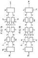
- the INTELSAT IESS-308 standard defines a coding / decoding system for digital data transmitted between a transmitter and a receiver. Such a system is shown in Figures 1A and 1B which respectively represent a transmitter and a receiver of digital data.
- a transmitter 1 receives at a bit rate Tb a digital train to be transmitted TNT.
- the digital TNT train is applied to the input of a demultiplexer 10 operating at the rate Tb.
- the demultiplexer 10 supplies two demultiplexed trains 11, 12 (even and odd bits respectively) to differential coding means constituted by differential coders 13a and 13b of the MDP-2 type.
- differential coders each supply a coded train 14, 15 to identical convolutional coders 16, 17.
- Each convolutional coder 16, 17 provides two bits for each bit applied to its input (efficiency 1/2).
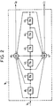
- a convolutional coder of this type for example coder 16, is shown in FIG. 2.
- the convolutional encoder 16 receives at each bit time a bit on its input 14 and also provides, at each bit time, two output bits Co and C1. It comprises six flip-flops 40 to 45 each delaying the signal by a bit time Tb. Two modulo 2 adders, referenced 46 and 47, provide Co and C1 which correspond to codings 171 and 133 in octal respectively. Each pair of two bits (Co, C1) and (C'o, C'1) from a convolutional encoder constitutes a code word.
- each multiplexer supplies one of the components Pt, Qt of a symbol to be transmitted. These components correspond respectively to the phase and quadrature components of a signal with 4 phase states (MDP-4 type signal).
- the components Pt and Qt are applied to means 20 of MDP-4 modulation and of transmission providing a transmitted symbol ST.
- the transmission considered in the invention is of the hertzian type and the receiver 2 of FIG. 1B receives the signals transmitted by the transmitter 1.
- the receiver 2 includes means 21 for receiving and demodulating the symbol transmitted and received, denoted SR, providing two components Pr, Qr of symbol received.
- the demodulation means include in particular a carrier recovery device. Each component is applied to a demultiplexer 22, 23 operating at the bit rate Tb and each providing, every two bit times, a code word received of two bits. These code words are (Ro, R'o) and (R1, R'1) and are applied to Viterbi decoders 24, 25, each providing an output decoded word 26, 27.
- the bits Ro and R1 are applied to the Viterbi decoder 24 and the bits R'o and R'1 to the Viterbi decoder 25.
- the decoded words 26, 27 are applied to differential decoding means constituted by differential decoders 28a and 28b which provide two decoded trains 29, 30.
- the differential decoders 28a and 28b ensure the ambiguity of the cycle jumps of ⁇ of the carrier recovery device, that is to say a phase shift of ⁇ between the carrier received and the local oscillator signal has no influence on the transmitted bits.
- a multiplexer 31 operating at bit rate Tb provides a digital train received TNR from the decoded trains 29 and 30.
- Table 1 represents the components received as a function of the phase jumps and Table 2 the bits received as a function of these same phase jumps.
- the received components Pr and Qr correspond either to the transmitted components, or to the inverse of these components.
- the Viterbi decoders ensure correct decoding since they are transparent to a phase jump of ⁇ . Differential decoding removes the ambiguity of ⁇ .
- the Viterbi decoders cannot find the components emitted and the metrics diverge. In fact, as shown in Table 2, the bits applied to the inputs of the same Viterbi decoder have undergone different coding (171 or 133).
- the present invention aims in particular to remedy these drawbacks.
- one of the objectives of the invention is to provide a data coding / decoding system which is transparent not only to phase jumps of ⁇ but also to phase jumps of ⁇ / 2.
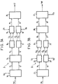
- FIGS. 3A and 3B respectively represent a transmitter and a receiver of digital data according to the invention. Elements identical to those of FIGS. 1A and 1B bear the same references.
- each code word (Co, C1) and (C'o, C'1) coming from one of the convolutional coders 16, 17 is applied to a single multiplexer 18, 19
- each bit of a code word received (Ro, R1) and (R'o, R'1) is applied to a single Viterbi decoder 22, 23.
- differential encoders 13a and 13b of FIG. 1A are replaced by a unique differential encoder 13 operating in MDP-4.
- differential decoders 28a and 28b are replaced by a unique differential decoder 28 of the MDP-4 type.
- the main objective of the invention which is to make the transmission system for phase jumps of ⁇ and ⁇ / 2 transparent, is achieved, as shown in table 3 below:
- phase jumps are in accordance with Table 1 previously described. More precisely, for a phase jump of 0 or ⁇ , the components received Pr and Qr correspond either to the components emitted, or to the inverse of these components, as well as in the state of the art. The removal of phase ambiguity from ⁇ is ensured by differential decoding of the MDP-4 type.
- the Viterbi decoders 24 and 25 receive code words which they recognize since the code words (C'o, C'1) or ( Co ⁇ , C1 ⁇ ) when a phase jump of + ⁇ / 2 occurs and ( Co ⁇ , It's 1 ⁇ ) or (Co, C1) when a phase jump of - ⁇ / 2 occurs.
- code words C'o, C'1 or ( Co ⁇ , C1 ⁇ ) when a phase jump of + ⁇ / 2 occurs and ( Co ⁇ , It's 1 ⁇ ) or (Co, C1) when a phase jump of - ⁇ / 2 occurs.
- the demultiplexers 22 and 23 can be those generally included in the Viterbi decoders and in this case the serial inputs of these decoders are used.
- the invention can be applied to continuous transmissions where the transmitted signals have a frame structure comprising a frame alignment word (single word or recognition word allowing synchronization) but finds a particularly interesting application in TDMA transmissions since a phase jump only generates a short packet of errors.
- a frame alignment word single word or recognition word allowing synchronization
- the unique word present in the preamble of each packet transmitted is used to synchronize the demultiplexers 22 and 23 (or then the Viterbi decoders 24 and 25 when the serial inputs of these decoders are used) at the start of the useful information, i.e. so that (Co, C1) and (C'o, C'1) correspond respectively to (Ro, R1) and (R'o, R'1).
- This synchronization can be obtained by means existing in the prior art, such as for example a single word detector as described in the aforementioned patent application.
Abstract
Description
Le domaine de l'invention est celui de la transmission de données numériques, notamment par voie hertzienne, et concerne plus précisément un système de codage et de décodage de données qui est transparent aux sauts de cycle de porteuse de π et π/2. Le système de l'invention peut notamment être utilisé pour la transmission de signaux par satellite entre un émetteur et un récepteur, par exemple pour une transmission en mode AMRT (Accès Multiple à Répartition dans le Temps).The field of the invention is that of the transmission of digital data, in particular by hertzian way, and relates more precisely to a system of coding and decoding of data which is transparent to the jumps of carrier cycle of π and π / 2. The system of the invention can in particular be used for the transmission of signals by satellite between a transmitter and a receiver, for example for a transmission in TDMA mode (Multiple Access with Distribution in Time).
Dans la suite de cette description, on considère une transmission de type MDP-4 (Modulation à Déplacement de Phase à 4 états de phase), c'est à dire que chaque couple de bits à transmettre est représenté par un échantillon dont la position dans un plan de phase complexe (constellation) est fonction de la valeur de ce couple.In the following of this description, we consider a transmission of the MDP-4 type (Phase Displacement Modulation with 4 phase states), that is to say that each pair of bits to be transmitted is represented by a sample whose position in a complex phase plan (constellation) is a function of the value of this couple.
Les systèmes de transmission numériques actuels emploient de plus en plus fréquemment des décodeurs correcteurs d'erreurs afin de pouvoir travailler à des rapports signal à bruit du signal reçu plus faibles. A titre d'exemple, un codage convolutif de taux 3/4 associé à un décodeur de Viterbi permet d'obtenir un gain de signal à bruit d'environ 4,3 dB pour un taux d'erreur binaire de 10⁻⁶.Current digital transmission systems are increasingly using error correcting decoders in order to be able to work at lower signal-to-noise ratios of the received signal. For example, a convolutive 3/4 rate coding associated with a Viterbi decoder makes it possible to obtain a signal-to-noise gain of approximately 4.3 dB for a bit error rate of 10⁻⁶.
Les émetteurs/récepteurs fonctionnant en mode AMRT utilisent également la correction d'erreur, avec toutefois des contraintes supplémentaires puisqu'il faut réaliser un compromis au niveau de la synchronisation de la récupération de porteuse. En effet, en AMRT, il est nécessaire d'effectuer une récupération de porteuse dans un temps suffisamment court pour que chaque paquet de données reçu soit correctement démodulé et les dispositifs de récupération de porteuse classiques, de type à base de boucle de contre-réaction (boucle de Costas, PLL,...), ne conviennent pas car ils sont trop lents. On utilise donc des dispositifs de type à boucle ouverte ("feedforward" en anglais) qui présentent des temps d'acquisition bien plus courts.Transmitters / receivers operating in TDMA mode also use error correction, with however additional constraints since it is necessary to make a compromise in terms of synchronization of carrier recovery. Indeed, in TDMA, it is necessary to carry out a carrier recovery in a sufficiently short time so that each received data packet is correctly demodulated and the conventional carrier recovery devices, of the feedback loop (Costas loop, PLL, ...), are not suitable because they are too slow. We therefore use open loop type devices ("feedforward" in English) which have much shorter acquisition times.
Ces derniers dispositifs emploient cependant nécessairement un filtre de récupération de porteuse dont la largeur de bande résulte d'un compromis entre :
- un temps d'acquisition de synchronisation faible, ce qui nécessite une large bande passante. Un temps d'acquisition de synchronisation faible est primordial en transmission AMRT car une variation de la fréquence porteuse pourra alors être rapidement prise en compte et le signal de démodulation sera rapidement calé en phase et en fréquence sur la porteuse du signal reçu. Les informations utiles de chaque paquet reçu seront alors correctement décodées ;
- une minimisation de la probabilité de saut de cycle, ce qui nécessite une bande passante étroite. Lorsque le canal de transmission est bruité, ce qui justifie par ailleurs l'utilisation du décodage correcteur d'erreurs, le signal de démodulation peut être affecté de sauts de phase ou encore de sauts de cycles de π et de π/2. Il s'en suit que la constellation du signal reçu est affectée d'une rotation et les symboles décodés ne correspondent plus aux symboles émis.
- a low synchronization acquisition time, which requires a large bandwidth. A low synchronization acquisition time is essential in TDMA transmission because a variation of the carrier frequency can then be quickly taken into account and the demodulation signal will be quickly calibrated in phase and in frequency on the carrier of the received signal. The useful information of each packet received will then be correctly decoded;
- minimization of the probability of cycle hopping, which requires a narrow bandwidth. When the transmission channel is noisy, which moreover justifies the use of error correcting decoding, the demodulation signal can be affected by phase jumps or else by cycle jumps of π and π / 2. It follows that the constellation of the received signal is rotated and the decoded symbols no longer correspond to the symbols transmitted.
On pourra se reporter notamment à la demande de brevet français n°93.07905 déposée le 29 juin 1993 qui décrit plus précisément ce problème connu.Reference may be made in particular to French patent application No. 93.07905 filed on June 29, 1993 which describes this known problem more precisely.
La diminution du rapport signal à bruit due à l'utilisation de décodeurs correcteurs d'erreurs a obligé les fabricants de matériel de télécommunications à réduire la bande passante du filtre de récupération de porteuse réception et par conséquent à rallonger la longueur du préambule de chaque paquet transmis en AMRT pour assurer qu'à la fin du préambule l'erreur de phase du signal de démodulation soit nulle. On appelle préambule un certain nombre de bits de synchronisation présents au début d'un paquet permettant au récepteur de se synchroniser en fréquence et en phase sur le signal reçu. La solution consistant à rallonger ce préambule n'est cependant pas acceptable car le rendement des paquets (nombre de bits de synchronisation / nombre total de bits dans un paquet) est alors diminué.The decrease in signal-to-noise ratio due to the use of error correcting decoders has forced manufacturers of telecommunications equipment to reduce the bandwidth of the receive carrier recovery filter and therefore to lengthen the preamble of each packet. transmitted in TDMA to ensure that at the end of the preamble the phase error of the signal demodulation is zero. A number of synchronization bits present at the start of a packet are called in the preamble, allowing the receiver to synchronize in frequency and in phase with the received signal. The solution consisting in lengthening this preamble is however not acceptable because the performance of the packets (number of synchronization bits / total number of bits in a packet) is then reduced.
La norme INTELSAT IESS-308 définit un système de codage/décodage de données numériques transmises entre un émetteur et un récepteur. Un tel système est représenté aux figures 1A et 1B qui représentent respectivement un émetteur et un récepteur de données numériques.The INTELSAT IESS-308 standard defines a coding / decoding system for digital data transmitted between a transmitter and a receiver. Such a system is shown in Figures 1A and 1B which respectively represent a transmitter and a receiver of digital data.
En regard de la figure 1A, un émetteur 1 reçoit à un rythme bit Tb un train numérique à transmettre TNT. Le train numérique TNT est appliqué à l'entrée d'un démultiplexeur 10 fonctionnant au rythme Tb. Le démultiplexeur 10 fournit deux trains démultiplexés 11, 12 (respectivement des bits pairs et impairs) à des moyens de codage différentiel constitués par des codeurs différentiels 13a et 13b de type MDP-2. Ces codeurs différentiels fournissent chacun un train codé 14, 15 à des codeurs convolutifs 16, 17 identiques. Chaque codeur convolutif 16, 17 fournit deux bits pour chaque bit appliqué à son entrée (rendement 1/2). La longueur de contrainte est par exemple égale à 7 et on peut utiliser un codeur ayant comme polynôme générateur G = (133, 171) en octal.With reference to FIG. 1A, a
Un codeur convolutif de ce type, par exemple le codeur 16, est représenté à la figure 2.A convolutional coder of this type, for
Le codeur convolutif 16 reçoit à chaque temps bit un bit sur son entrée 14 et fournit, également à chaque temps bit, deux bits de sortie Co et C1. Il comporte six bascules 40 à 45 retardant chacune le signal d'un temps bit Tb. Deux additionneurs modulo 2, référencés 46 et 47, fournissent Co et C1 qui correspondent aux codages 171 et 133 en octal respectivement. Chaque couple de deux bits (Co, C1) et (C'o, C'1) issu d'un codeur convolutif constitue un mot de code.The
En se référant à nouveau à la figure 1A, les bits Co et C'o sont appliqués à l'entrée d'un multiplexeur 18 et les bits C1 et C'1 à l'entrée d'un multiplexeur 19. On a donc un entrelacement des voies de traitement. Les deux multiplexeurs fonctionnent au rythme bit Tb pour alternativement fournir sur leurs sorties les bits appliqués sur leurs entrées. Ainsi, à chaque temps bit, chaque multiplexeur fournit une des composantes Pt, Qt d'un symbole à transmettre. Ces composantes correspondent respectivement aux composantes en phase et en quadrature d'un signal à 4 états de phase (signal de type MDP-4). Les composantes Pt et Qt sont appliquées à des moyens 20 de modulation MDP-4 et de transmission fournissant un symbole transmis ST.Referring again to FIG. 1A, the bits Co and C'o are applied to the input of a
La transmission considérée dans l'invention est de type hertzienne et le récepteur 2 de la figure 1B reçoit les signaux transmis par l'émetteur 1.The transmission considered in the invention is of the hertzian type and the
Le récepteur 2 comporte des moyens 21 de réception et de démodulation du symbole transmis et reçu, noté SR, fournissant deux composantes Pr, Qr de symbole reçu. Les moyens de démodulation comportent notamment un dispositif de récupération de porteuse. Chaque composante est appliquée à un démultiplexeur 22, 23 fonctionnant au rythme bit Tb et fournissant chacun, tous les deux temps bit, un mot de code reçu de deux bits. Ces mots de code sont (Ro, R'o) et (R1, R'1) et sont appliqués à des décodeurs de Viterbi 24, 25, fournissant chacun un mot décodé 26, 27 de sortie. Les bits Ro et R1 sont appliqués au décodeur de Viterbi 24 et les bits R'o et R'1 au décodeur de Viterbi 25. Les mots décodés 26, 27 sont appliqués à des moyens de décodage différentiel constitués par des décodeurs différentiels 28a et 28b qui fournissent deux trains décodés 29, 30. Les décodeurs différentiels 28a et 28b assurent une levée d'ambiguïté des sauts de cycle de π du dispositif de récupération de porteuse, c'est à dire qu'un déphasage de π entre la porteuse reçue et le signal d'oscillateur local n'a pas d'influence sur les bits transmis. Un multiplexeur 31 fonctionnant au rythme bit Tb fournit un train numérique reçu TNR à partir des trains décodés 29 et 30.The
Dans un système de transmission de ce type, deux voies de traitement parallèles sont donc utilisées. Ceci permet de doubler le débit de transmission puisque deux codeurs et deux décodeurs fonctionnent en parallèle en MDP-2.In a transmission system of this type, two parallel processing channels are therefore used. This makes it possible to double the transmission rate since two encoders and two decoders operate in parallel in MDP-2.
Le gain de rapport signal à bruit apporté par un codage correcteur d'erreurs peut cependant être annihilé par les sauts de cycles indésirables. En effet, un saut de cycle porteuse entraîne une inversion entre les bits présentés aux entrées d'un décodeur et on observe alors une divergence des métriques. Le décodeur de Viterbi nécessitera alors un temps important pour se rendre compte de cette divergence et la convergence des métriques nécessite plusieurs milliers de symboles. En conséquences, si un saut de cycle se produit au cours de la réception d'un paquet ou même au début d'un paquet reçu, par exemple pendant la réception d'un préambule, le reste du paquet sera perdu.The gain in signal-to-noise ratio provided by error correcting coding can however be canceled out by undesired cycle jumps. Indeed, a carrier cycle jump results in an inversion between the bits presented at the inputs of a decoder and a divergence of the metrics is then observed. The Viterbi decoder will then require significant time to realize this divergence and the convergence of the metrics requires several thousand symbols. Consequently, if a cycle jump occurs during the reception of a packet or even at the start of a received packet, for example during the reception of a preamble, the rest of the packet will be lost.
Ce phénomène d'inversion des bits est mis en évidence dans les tableaux 1 et 2 ci-dessous. Le tableau 1 représente les composantes reçues en fonction des sauts de phase et le tableau 2 les bits reçus en fonction de ces mêmes sauts de phase.


Pour un saut de phase de 0 ou de π, les composantes reçues Pr et Qr correspondent soit aux composantes émises, soit à l'inverse de ces composantes. Dans ces deux cas, les décodeurs de Viterbi assurent un décodage correct puisqu'ils sont transparents à un saut de phase de π. Le décodage différentiel permet de lever l'ambiguïté de π. En revanche, pour des sauts de phase de ±π/2, les décodeurs de Viterbi ne peuvent pas retrouver les composantes émises et les métriques divergent. En effet, comme montré dans le tableau 2, les bits appliqués aux entrées d'un même décodeur de Viterbi ont subi un codage différent (171 ou 133). Par exemple, pour un saut de phase de π/2, l'entrée Ro du décodeur, qui s'attend à recevoir un bit codé selon le code 171, reçoit le bit C1 qui a été codé selon le code 133. Il s'en suit que les décodeurs de Viterbi ne peuvent retrouver les bits émis. Dans une transmission continue, ceci se traduit par une perte de synchronisation, alors qu'en transmission AMRT, le paquet entier reçu est perdu. On notera que cet inconvénient résulte du fait que les codages 171 et 133 sont transparents aux sauts de phase de π et non aux sauts de ±π/2.For a phase jump of 0 or π, the received components Pr and Qr correspond either to the transmitted components, or to the inverse of these components. In these two cases, the Viterbi decoders ensure correct decoding since they are transparent to a phase jump of π. Differential decoding removes the ambiguity of π. On the other hand, for phase jumps of ± π / 2, the Viterbi decoders cannot find the components emitted and the metrics diverge. In fact, as shown in Table 2, the bits applied to the inputs of the same Viterbi decoder have undergone different coding (171 or 133). For example, for a phase jump of π / 2, the input Ro of the decoder, which expects to receive a bit coded according to code 171, receives bit C1 which has been coded according to code 133. It is it follows that the Viterbi decoders cannot recover the transmitted bits. In a continuous transmission, this results in a loss of synchronization, while in TDMA transmission, the entire received packet is lost. It will be noted that this drawback results from the fact that the codings 171 and 133 are transparent to phase jumps of π and not to jumps of ± π / 2.
La présente invention a notamment pour objectif de remédier à ces inconvénients.The present invention aims in particular to remedy these drawbacks.
Plus précisément, un des objectifs de l'invention est de fournir un système de codage/décodage de données qui soit transparent non seulement aux sauts de phase de π mais également aux sauts de phase de π/2.More precisely, one of the objectives of the invention is to provide a data coding / decoding system which is transparent not only to phase jumps of π but also to phase jumps of π / 2.
Cet objectif, ainsi que d'autres qui apparaîtront par la suite, est atteint grâce à un système de codage/décodage de données numériques transmises entre un émetteur et un récepteur, l'émetteur comprenant :
- un démultiplexeur recevant un train numérique à transmettre et fournissant deux trains démultiplexés au rythme bit ;
- un codeur différentiel de type MDP-4 recevant les trains démultiplexés et fournissant deux trains codés ;
- deux codeurs convolutifs recevant chacun un des trains codés et fournissant chacun un mot de code pour chaque bit de train codé reçu ;
- deux multiplexeurs des mots de code fonctionnant au rythme bit et fournissant chacun une des composantes d'un symbole à transmettre ;
- des moyens de modulation et de transmission du symbole fournissant un symbole transmis,
le récepteur comprenant :
- des moyens de réception et de démodulation du symbole transmis fournissant deux composantes de symbole reçu ;
- deux démultiplexeurs recevant chacun une des composantes du symbole reçu et fournissant chacun un mot de code reçu au rythme bit ;
- deux décodeurs de Viterbi fournissant chacun un mot décodé à partir des mots de code reçus ;
- un décodeur différentiel de type MDP-4 recevant les mots décodés et fournissant deux trains décodés ;
- un multiplexeur des trains décodés fournissant un train numérique reçu,
chaque mot de code issu d'un des codeurs convolutifs étant appliqué à un multiplexeur unique et chaque bit d'un mot de code reçu étant appliqué à un décodeur de Viterbi unique. Les données numériques transmises entre l'émetteur et le récepteur présentent une structure de trame comportant un mot de verrouillage trame. Un tel mot de verrouillage est également appelé mot unique ou mot de reconnaissance et permet au récepteur de se synchroniser sur le signal reçu pour faire correspondre Ro à Co, R1 à C1, R'o à C'o et R'1 à C'1 respectivement.This objective, as well as others which will appear subsequently, is achieved by means of a coding / decoding system of digital data transmitted between a transmitter and a receiver, the transmitter comprising:
- a demultiplexer receiving a digital train to be transmitted and providing two bit-rate demultiplexed trains;
- an MDP-4 type differential encoder receiving the demultiplexed trains and providing two coded trains;
- two convolutional coders each receiving one of the coded trains and each providing a code word for each coded train bit received;
- two multiplexers of code words operating at bit rate and each providing one of the components of a symbol to be transmitted;
- means for modulating and transmitting the symbol providing a transmitted symbol,
the receiver comprising:
- means for receiving and demodulating the transmitted symbol providing two components of the received symbol;
- two demultiplexers each receiving one of the components of the symbol received and each supplying a code word received at bit rate;
- two Viterbi decoders each supplying a decoded word from the code words received;
- an MDP-4 type differential decoder receiving the decoded words and providing two decoded trains;
- a multiplexer of the decoded trains providing a digital train received,
each code word from one of the convolutional coders being applied to a single multiplexer and each bit of a received code word being applied to a single Viterbi decoder. The digital data transmitted between the transmitter and the receiver has a frame structure comprising a frame lock word. Such a locking word is also called a single word or recognition word and allows the receiver to synchronize with the received signal to match Ro to Co, R1 to C1, R'o to C'o and R'1 to C ' 1 respectively.
En supprimant l'entrelacement des voies de traitement au niveau émetteur et récepteur, les mots de code appliqués aux entrées des décodeurs de Viterbi correspondent ainsi effectivement à des mots codés et ces décodeurs ne divergent pas. Les codeurs convolutifs peuvent ainsi fournir des mots de code non transparents aux sauts de phase de π/2 et donc avoir comme polynôme générateur G = (171, 133).By eliminating the interleaving of the processing channels at the transmitter and receiver level, the code words applied to the inputs of the Viterbi decoders thus effectively correspond to coded words and these decoders do not diverge. Convolutional coders can thus provide non-transparent code words to phase jumps of π / 2 and therefore have as generator polynomial G = (171, 133).
D'autres caractéristiques et avantages de l'invention apparaîtront à la lecture de la description suivante d'un mode de réalisation préférentiel, donné à titre illustratif et non limitatif, et des dessins annexés, dans lesquels :
- les figures 1A et 1B représentent respectivement un émetteur et un récepteur de données numériques répondant à la norme INTELSAT IESS-308 ;
- la figure 2 représente un codeur convolutif ayant comme polynôme générateur G = (171, 133) ;
- les figures 3A et 3B représentent respectivement un émetteur et un récepteur de données numériques selon l'invention.
- FIGS. 1A and 1B respectively represent a transmitter and a receiver of digital data corresponding to the INTELSAT IESS-308 standard;
- FIG. 2 represents a convolutional coder having as generator polynomial G = (171, 133);
- FIGS. 3A and 3B respectively represent a transmitter and a receiver of digital data according to the invention.
Les figures 1A, 1B et 2 ont été décrites précédemment en référence à l'état de la technique.Figures 1A, 1B and 2 have been described above with reference to the state of the art.
Les figures 3A et 3B représentent respectivement un émetteur et un récepteur de données numériques selon l'invention. Les éléments identiques à ceux des figures 1A et 1B portent les mêmes références.FIGS. 3A and 3B respectively represent a transmitter and a receiver of digital data according to the invention. Elements identical to those of FIGS. 1A and 1B bear the same references.
L'invention se distingue notamment de l'état de la technique en ce que les voies de traitement ne sont plus entrelacées. Ainsi, dans l'émetteur 3 de la figure 3A, chaque mot de code (Co, C1) et (C'o, C'1) issu d'un des codeurs convolutifs 16, 17 est appliqué à un multiplexeur unique 18, 19. De même, dans le récepteur 4 de la figure 3B, chaque bit d'un mot de code reçu (Ro, R1) et (R'o, R'1) est appliqué à un décodeur de Viterbi unique 22, 23.The invention differs in particular from the state of the art in that the processing paths are no longer interlaced. Thus, in the
De plus, les codeurs différentiels 13a et 13b de la figure 1A sont remplacés par un codeur différentiel 13 unique fonctionnant en MDP-4. De même, au niveau du récepteur, les décodeurs différentiels 28a et 28b sont remplacés par un décodeur différentiel unique 28 de type MDP-4.In addition, the
L'objectif principal de l'invention qui est de rendre transparent le système de transmission aux sauts de phase de π et de π/2 est atteint, comme montré dans le tableau 3 ci-dessous :

Les sauts de phase sont conformes au tableau 1 précédemment décrit. Plus précisément, pour un saut de phase de 0 ou de π, les composantes reçues Pr et Qr correspondent soit aux composantes émises, soit à l'inverse de ces composantes, de même que dans l'état de la technique. La levée d'ambiguïté de phase de π est assurée par le décodage différentiel de type MDP-4.The phase jumps are in accordance with Table 1 previously described. More precisely, for a phase jump of 0 or π, the components received Pr and Qr correspond either to the components emitted, or to the inverse of these components, as well as in the state of the art. The removal of phase ambiguity from π is ensured by differential decoding of the MDP-4 type.
En revanche, pour des sauts de phase de ±π/2, les décodeurs de Viterbi 24 et 25 reçoivent des mots de code qu'ils reconnaissent puisque leur sont appliqués les mots de code (C'o, C'1) ou (![]()
![]()
![]()
![]()
![]()
![]()
![]()
![]()
On peut noter que les démultiplexeurs 22 et 23 peuvent être ceux généralement compris dans les décodeurs de Viterbi et on utilise dans ce cas les entrées série de ces décodeurs.It can be noted that the
L'invention peut s'appliquer aux transmissions continues où les signaux transmis présentent une structure de trame comportant un mot de verrouillage de trame (mot unique ou mot de reconnaissance permettant une synchronisation) mais trouve une application particulièrement intéressante dans les transmissions AMRT puisqu'un saut de phase ne génère qu'un court paquet d'erreurs.The invention can be applied to continuous transmissions where the transmitted signals have a frame structure comprising a frame alignment word (single word or recognition word allowing synchronization) but finds a particularly interesting application in TDMA transmissions since a phase jump only generates a short packet of errors.
Dans une transmission AMRT, on utilise le mot unique présent dans le préambule de chaque paquet transmis pour synchroniser les démultiplexeurs 22 et 23 (ou alors les décodeurs de Viterbi 24 et 25 lorsque les entrées série de ces décodeurs sont utilisées) en début de l'information utile, c'est à dire pour que (Co, C1) et (C'o, C'1) correspondent respectivement à (Ro, R1) et (R'o, R'1). Cette synchronisation peut être obtenue par des moyens existants dans l'état de la technique, comme par exemple un détecteur de mot unique tel que décrit dans la demande de brevet précitée.In a TDMA transmission, the unique word present in the preamble of each packet transmitted is used to synchronize the
Des simulations ont montré qu'en l'absence de bruit le nombre d'erreurs lors d'un saut de cycle porteuse ne dépasse pas 50 pour un code poinçonné 3/4. Un poinçonneur est à cet effet inséré entre le codeur différentiel 13 et les multiplexeurs 16 et 17, alors qu'un dépoinçonneur est inséré entre les démultiplexeurs 22 et 23 et les décodeurs de Viterbi 24, 25. En présence de bruit (Eb/No = 4 dB), le nombre maximum d'erreurs par paquet est voisin de 60, avec une moyenne de 25 erreurs par paquet. Pour un code non poinçonné de rendement 1/2 et en l'absence de bruit, le nombre d'erreurs par paquet est inférieur à 22 avec une moyenne de 7,5 erreurs par paquet.Simulations have shown that in the absence of noise, the number of errors during a carrier cycle jump does not exceed 50 for a code marked 3/4. A punch is inserted for this purpose between the
Claims (4)
Applications Claiming Priority (2)
| Application Number | Priority Date | Filing Date | Title |
|---|---|---|---|
| FR9401876 | 1994-02-18 | ||
| FR9401876A FR2716588B1 (en) | 1994-02-18 | 1994-02-18 | Convolutional coding and decoding system of viterbi transparent to the phase jumps of pi and pi / 2, applicable in particular to TDMA transmissions. |
Publications (2)
| Publication Number | Publication Date |
|---|---|
| EP0668682A1 true EP0668682A1 (en) | 1995-08-23 |
| EP0668682B1 EP0668682B1 (en) | 2001-01-31 |
Family
ID=9460226
Family Applications (1)
| Application Number | Title | Priority Date | Filing Date |
|---|---|---|---|
| EP95400320A Expired - Lifetime EP0668682B1 (en) | 1994-02-18 | 1995-02-15 | System of convolutional coding and Viterbi decoding, transparent to phase shifts of pi and pi/2 in PSK-4 transmission |
Country Status (5)
| Country | Link |
|---|---|
| US (1) | US5555547A (en) |
| EP (1) | EP0668682B1 (en) |
| CA (1) | CA2142769C (en) |
| DE (1) | DE69520009T2 (en) |
| FR (1) | FR2716588B1 (en) |
Cited By (1)
| Publication number | Priority date | Publication date | Assignee | Title |
|---|---|---|---|---|
| CN103036602A (en) * | 2011-09-30 | 2013-04-10 | 中兴通讯股份有限公司 | Method, device and system for multipoint cooperation transmission precoding processing |
Families Citing this family (14)
| Publication number | Priority date | Publication date | Assignee | Title |
|---|---|---|---|---|
| US5835487A (en) | 1995-12-08 | 1998-11-10 | Worldspace International Network, Inc. | Satellite direct radio broadcast system |
| JPH09181618A (en) * | 1995-12-27 | 1997-07-11 | Nec Corp | Data transmitter |
| EP0846387A1 (en) * | 1996-06-26 | 1998-06-10 | Koninklijke Philips Electronics N.V. | Trellis coded qam using rate compatible, punctured, convolutional codes |
| KR0171029B1 (en) * | 1996-06-28 | 1999-03-30 | 정선종 | Pulse shaping filter for ñ/4 transfer qpsk modulator |
| US6542480B1 (en) * | 1996-11-05 | 2003-04-01 | Worldspace, Inc. | Satellite payload processing system using polyphase demultiplexing, quadrature phase shift keying demodulation and rate alignment |
| US5864546A (en) * | 1996-11-05 | 1999-01-26 | Worldspace International Network, Inc. | System for formatting broadcast data for satellite transmission and radio reception |
| US5867490A (en) * | 1996-11-05 | 1999-02-02 | Worldspace International Network, Inc. | Direct radio broadcast receiver for providing frame synchronization and correlation for time division multiplexed transmissions |
| US6201798B1 (en) | 1997-11-14 | 2001-03-13 | Worldspace Management Corporation | Signaling protocol for satellite direct radio broadcast system |
| JP2001523916A (en) * | 1997-11-14 | 2001-11-27 | ワールドスペース マネイジメント コーポレーション | Signaling protocol for satellite direct radio broadcasting system |
| US6158041A (en) * | 1998-10-14 | 2000-12-05 | Cisco Technology | System and method for I/Q trellis coded modulation |
| US6560292B1 (en) * | 2000-04-07 | 2003-05-06 | Qualcomm Incorporated | Method for coding in a telecommunications system |
| US6954492B1 (en) * | 2000-04-19 | 2005-10-11 | 3Com Corporation | Method of differential encoding a precoded multiple modulus encoder |
| US6735258B1 (en) * | 2000-09-29 | 2004-05-11 | Arraycomm, Inc. | Moderate rate phase shift keying codec |
| US6448910B1 (en) | 2001-03-26 | 2002-09-10 | Morpho Technologies | Method and apparatus for convolution encoding and viterbi decoding of data that utilize a configurable processor to configure a plurality of re-configurable processing elements |
Citations (3)
| Publication number | Priority date | Publication date | Assignee | Title |
|---|---|---|---|---|
| US5023889A (en) * | 1988-05-31 | 1991-06-11 | California Institute Of Technology | Trellis coded multilevel DPSK system with doppler correction for mobile satellite channels |
| EP0486729A1 (en) * | 1989-07-28 | 1992-05-27 | AT&T Corp. | Coded modulation for mobile radio |
| WO1992020162A2 (en) * | 1991-05-03 | 1992-11-12 | Qualcomm Incorporated | Method and apparatus for resolving phase ambiguities in trellis coded modulated data |
Family Cites Families (4)
| Publication number | Priority date | Publication date | Assignee | Title |
|---|---|---|---|---|
| US4489418A (en) * | 1983-04-18 | 1984-12-18 | At&T Bell Laboratories | Differential encoding technique |
| US4713817A (en) * | 1985-04-25 | 1987-12-15 | Codex Corporation | Multidimensional, convolutionally coded communication systems |
| DE3730547A1 (en) * | 1987-09-11 | 1989-03-23 | Ant Nachrichtentech | METHOD FOR PROCESSING DATA |
| JPH0481054A (en) * | 1990-06-01 | 1992-03-13 | Nec Corp | Data transmission system |
-
1994
- 1994-02-18 FR FR9401876A patent/FR2716588B1/en not_active Expired - Fee Related
-
1995
- 1995-02-15 DE DE69520009T patent/DE69520009T2/en not_active Expired - Lifetime
- 1995-02-15 EP EP95400320A patent/EP0668682B1/en not_active Expired - Lifetime
- 1995-02-15 US US08/388,820 patent/US5555547A/en not_active Expired - Lifetime
- 1995-02-17 CA CA002142769A patent/CA2142769C/en not_active Expired - Fee Related
Patent Citations (3)
| Publication number | Priority date | Publication date | Assignee | Title |
|---|---|---|---|---|
| US5023889A (en) * | 1988-05-31 | 1991-06-11 | California Institute Of Technology | Trellis coded multilevel DPSK system with doppler correction for mobile satellite channels |
| EP0486729A1 (en) * | 1989-07-28 | 1992-05-27 | AT&T Corp. | Coded modulation for mobile radio |
| WO1992020162A2 (en) * | 1991-05-03 | 1992-11-12 | Qualcomm Incorporated | Method and apparatus for resolving phase ambiguities in trellis coded modulated data |
Non-Patent Citations (2)
| Title |
|---|
| 40th IEEE Vehicular Technology Conference, 6-9/5/1990, Orlando, US; IEEE, New York, US, 1990; pages 471 - 475, Elnoubi et al.: "Performance of trellis coded QPSK * |
| Eleventh Annual International Phoenix Conference on Computers and Communications, 1-3/4/1992, Scottsdale, US; pages 232 - 239, Ross et al.: * |
Cited By (2)
| Publication number | Priority date | Publication date | Assignee | Title |
|---|---|---|---|---|
| CN103036602A (en) * | 2011-09-30 | 2013-04-10 | 中兴通讯股份有限公司 | Method, device and system for multipoint cooperation transmission precoding processing |
| CN103036602B (en) * | 2011-09-30 | 2017-11-24 | 中兴通讯股份有限公司 | Coordinated multipoint transmission recoding processing method, apparatus and system |
Also Published As
| Publication number | Publication date |
|---|---|
| CA2142769C (en) | 2000-10-03 |
| FR2716588B1 (en) | 1996-03-29 |
| CA2142769A1 (en) | 1995-08-19 |
| DE69520009D1 (en) | 2001-03-08 |
| US5555547A (en) | 1996-09-10 |
| EP0668682B1 (en) | 2001-01-31 |
| FR2716588A1 (en) | 1995-08-25 |
| DE69520009T2 (en) | 2001-09-06 |
Similar Documents
| Publication | Publication Date | Title |
|---|---|---|
| EP0668682B1 (en) | System of convolutional coding and Viterbi decoding, transparent to phase shifts of pi and pi/2 in PSK-4 transmission | |
| EP0559883B1 (en) | Device for digital transmission and direct conversion receiver | |
| FR2802371A1 (en) | METHOD FOR SIGNALING IN A RADIOCOMMUNICATION SYSTEM, TRANSMITTERS, RECEIVERS AND REPEATERS FOR IMPLEMENTING THE METHOD | |
| EP0608024A1 (en) | Transmissionsystem with clock recovery | |
| EP2099137A2 (en) | Differential spatial-temporal coding method | |
| EP2795818A1 (en) | Method for transmitting a digital signal for a non-orthogonal ms-marc system, and corresponding programme product and relay device | |
| FR2730883A1 (en) | DEVICE FOR INITIALIZING A VITERBI DECODER INCLUDED IN A RECEIVER OF SIGNALS TRANSMITTED IN THE FORM OF TRANSMITTER, RECEIVER AND CORRESPONDING PROCESS PACKETS | |
| EP2767020B1 (en) | Method and system of communication using dynamic modulation and coding schemes on wide band hf communication channels | |
| EP0774840B1 (en) | Information bit sequence transmission method with selective protection against transmission errors, transmission method using such a coding and correction method | |
| EP0629059B1 (en) | Spread spectrum digital transmission system with low frequency pseudorandom coding of the useful information and method for spectrum spreading and compressing used in such a system | |
| EP3224978A1 (en) | Method and device for flexible, selective ssdf relaying | |
| EP3840233B1 (en) | Circuit for detecting an enclosure and receiver including said circuit | |
| WO2005124383A1 (en) | Method for transmitting a radio navigation signal | |
| Jayasimha et al. | Satellite-based AIS receiver for dense maritime zones | |
| CA2358719C (en) | Broadcasting system, and process ensuring the continuity of service | |
| EP0731588B1 (en) | Multiresolution phase modulation, for multicarrier systems | |
| FR3085568A1 (en) | METHOD FOR DATE OF TELEMETRY SIGNALS | |
| EP0616743A1 (en) | Combination of two signals, the second appearing as a noise for the first one | |
| EP2220799A2 (en) | Synchro-frame method based on the discrete logarithm | |
| EP0645894B1 (en) | Transmission system using trellis or block coded modulation receiver and decoder therefor | |
| EP0272956B1 (en) | Digital transmission system with a coherent demodulation adapted to the simultaneous transmission of two binary signals | |
| WO2024017554A1 (en) | Symbol timing synchronization device and method with a parallel architecture | |
| JP2800855B2 (en) | Digital wireless communication system | |
| EP3963757A1 (en) | Method and receiver device for detecting the start of a frame of a satellite communications signal | |
| EP0644663A1 (en) | Method and apparatus for synchronisation in a direct sequence spread spectrum digital transmission system |
Legal Events
| Date | Code | Title | Description |
|---|---|---|---|
| PUAI | Public reference made under article 153(3) epc to a published international application that has entered the european phase |
Free format text: ORIGINAL CODE: 0009012 |
|
| AK | Designated contracting states |
Kind code of ref document: A1 Designated state(s): DE ES FR GB IT NL SE |
|
| 17P | Request for examination filed |
Effective date: 19951230 |
|
| GRAG | Despatch of communication of intention to grant |
Free format text: ORIGINAL CODE: EPIDOS AGRA |
|
| RTI1 | Title (correction) |
Free format text: SYSTEM OF CONVOLUTIONAL CODING AND VITERBI DECODING, TRANSPARENT TO PHASE SHIFTS OF PI AND PI/2 IN PSK-4 TRANSMISSION |
|
| 17Q | First examination report despatched |
Effective date: 20000217 |
|
| GRAG | Despatch of communication of intention to grant |
Free format text: ORIGINAL CODE: EPIDOS AGRA |
|
| GRAH | Despatch of communication of intention to grant a patent |
Free format text: ORIGINAL CODE: EPIDOS IGRA |
|
| GRAH | Despatch of communication of intention to grant a patent |
Free format text: ORIGINAL CODE: EPIDOS IGRA |
|
| GRAA | (expected) grant |
Free format text: ORIGINAL CODE: 0009210 |
|
| RAP1 | Party data changed (applicant data changed or rights of an application transferred) |
Owner name: ALCATEL |
|
| AK | Designated contracting states |
Kind code of ref document: B1 Designated state(s): DE ES FR GB IT NL SE |
|
| PG25 | Lapsed in a contracting state [announced via postgrant information from national office to epo] |
Ref country code: SE Free format text: THE PATENT HAS BEEN ANNULLED BY A DECISION OF A NATIONAL AUTHORITY Effective date: 20010131 Ref country code: NL Free format text: LAPSE BECAUSE OF FAILURE TO SUBMIT A TRANSLATION OF THE DESCRIPTION OR TO PAY THE FEE WITHIN THE PRESCRIBED TIME-LIMIT Effective date: 20010131 Ref country code: IT Free format text: LAPSE BECAUSE OF FAILURE TO SUBMIT A TRANSLATION OF THE DESCRIPTION OR TO PAY THE FEE WITHIN THE PRESCRIBED TIME-LIMIT;WARNING: LAPSES OF ITALIAN PATENTS WITH EFFECTIVE DATE BEFORE 2007 MAY HAVE OCCURRED AT ANY TIME BEFORE 2007. THE CORRECT EFFECTIVE DATE MAY BE DIFFERENT FROM THE ONE RECORDED. Effective date: 20010131 Ref country code: ES Free format text: THE PATENT HAS BEEN ANNULLED BY A DECISION OF A NATIONAL AUTHORITY Effective date: 20010131 |
|
| REF | Corresponds to: |
Ref document number: 69520009 Country of ref document: DE Date of ref document: 20010308 |
|
| GBT | Gb: translation of ep patent filed (gb section 77(6)(a)/1977) |
Effective date: 20010221 |
|
| NLV1 | Nl: lapsed or annulled due to failure to fulfill the requirements of art. 29p and 29m of the patents act | ||
| PLBE | No opposition filed within time limit |
Free format text: ORIGINAL CODE: 0009261 |
|
| STAA | Information on the status of an ep patent application or granted ep patent |
Free format text: STATUS: NO OPPOSITION FILED WITHIN TIME LIMIT |
|
| REG | Reference to a national code |
Ref country code: GB Ref legal event code: IF02 |
|
| 26N | No opposition filed | ||
| REG | Reference to a national code |
Ref country code: FR Ref legal event code: CD |
|
| PGFP | Annual fee paid to national office [announced via postgrant information from national office to epo] |
Ref country code: DE Payment date: 20120208 Year of fee payment: 18 |
|
| PGFP | Annual fee paid to national office [announced via postgrant information from national office to epo] |
Ref country code: GB Payment date: 20120215 Year of fee payment: 18 |
|
| GBPC | Gb: european patent ceased through non-payment of renewal fee |
Effective date: 20130215 |
|
| REG | Reference to a national code |
Ref country code: DE Ref legal event code: R119 Ref document number: 69520009 Country of ref document: DE Effective date: 20130903 |
|
| PG25 | Lapsed in a contracting state [announced via postgrant information from national office to epo] |
Ref country code: GB Free format text: LAPSE BECAUSE OF NON-PAYMENT OF DUE FEES Effective date: 20130215 Ref country code: DE Free format text: LAPSE BECAUSE OF NON-PAYMENT OF DUE FEES Effective date: 20130903 |
|
| PGFP | Annual fee paid to national office [announced via postgrant information from national office to epo] |
Ref country code: FR Payment date: 20140211 Year of fee payment: 20 |