EP2099137A2 - Differential spatial-temporal coding method - Google Patents
Differential spatial-temporal coding method Download PDFInfo
- Publication number
- EP2099137A2 EP2099137A2 EP09153838A EP09153838A EP2099137A2 EP 2099137 A2 EP2099137 A2 EP 2099137A2 EP 09153838 A EP09153838 A EP 09153838A EP 09153838 A EP09153838 A EP 09153838A EP 2099137 A2 EP2099137 A2 EP 2099137A2
- Authority
- EP
- European Patent Office
- Prior art keywords
- matrix
- elements
- uwb
- radiative
- signal
- Prior art date
- Legal status (The legal status is an assumption and is not a legal conclusion. Google has not performed a legal analysis and makes no representation as to the accuracy of the status listed.)
- Withdrawn
Links
Images


Classifications
-
- H—ELECTRICITY
- H04—ELECTRIC COMMUNICATION TECHNIQUE
- H04L—TRANSMISSION OF DIGITAL INFORMATION, e.g. TELEGRAPHIC COMMUNICATION
- H04L1/00—Arrangements for detecting or preventing errors in the information received
- H04L1/02—Arrangements for detecting or preventing errors in the information received by diversity reception
- H04L1/06—Arrangements for detecting or preventing errors in the information received by diversity reception using space diversity
- H04L1/0612—Space-time modulation
-
- H—ELECTRICITY
- H04—ELECTRIC COMMUNICATION TECHNIQUE
- H04B—TRANSMISSION
- H04B1/00—Details of transmission systems, not covered by a single one of groups H04B3/00 - H04B13/00; Details of transmission systems not characterised by the medium used for transmission
- H04B1/69—Spread spectrum techniques
- H04B1/7163—Spread spectrum techniques using impulse radio
- H04B1/71635—Transmitter aspects
-
- H—ELECTRICITY
- H04—ELECTRIC COMMUNICATION TECHNIQUE
- H04B—TRANSMISSION
- H04B1/00—Details of transmission systems, not covered by a single one of groups H04B3/00 - H04B13/00; Details of transmission systems not characterised by the medium used for transmission
- H04B1/69—Spread spectrum techniques
- H04B1/7163—Spread spectrum techniques using impulse radio
- H04B1/7176—Data mapping, e.g. modulation
-
- H—ELECTRICITY
- H04—ELECTRIC COMMUNICATION TECHNIQUE
- H04B—TRANSMISSION
- H04B7/00—Radio transmission systems, i.e. using radiation field
- H04B7/02—Diversity systems; Multi-antenna system, i.e. transmission or reception using multiple antennas
- H04B7/04—Diversity systems; Multi-antenna system, i.e. transmission or reception using multiple antennas using two or more spaced independent antennas
- H04B7/0413—MIMO systems
-
- H—ELECTRICITY
- H04—ELECTRIC COMMUNICATION TECHNIQUE
- H04L—TRANSMISSION OF DIGITAL INFORMATION, e.g. TELEGRAPHIC COMMUNICATION
- H04L25/00—Baseband systems
- H04L25/38—Synchronous or start-stop systems, e.g. for Baudot code
- H04L25/40—Transmitting circuits; Receiving circuits
- H04L25/49—Transmitting circuits; Receiving circuits using code conversion at the transmitter; using predistortion; using insertion of idle bits for obtaining a desired frequency spectrum; using three or more amplitude levels ; Baseband coding techniques specific to data transmission systems
- H04L25/4902—Pulse width modulation; Pulse position modulation
-
- H—ELECTRICITY
- H04—ELECTRIC COMMUNICATION TECHNIQUE
- H04L—TRANSMISSION OF DIGITAL INFORMATION, e.g. TELEGRAPHIC COMMUNICATION
- H04L1/00—Arrangements for detecting or preventing errors in the information received
- H04L1/02—Arrangements for detecting or preventing errors in the information received by diversity reception
- H04L1/06—Arrangements for detecting or preventing errors in the information received by diversity reception using space diversity
- H04L1/0618—Space-time coding
- H04L1/0637—Properties of the code
- H04L1/0668—Orthogonal systems, e.g. using Alamouti codes
Definitions
- the invention relates to the field of space-time coding STC (Space Time Coding) for multi-antenna systems, particularly for applications in ultra-wideband, or UWB telecommunications (Ultra Wide Band).
- STC Space Time Coding
- Wireless telecommunication systems of the multi-antenna type are well known in the state of the art. These systems use a plurality of transmit and / or receive antennas and are called, according to the type of configuration adopted, Multiple Input Multiple Output (MIMO), Multiple Input Single Output (MISO) or Single Input Multiple (SIMO). Output ). Subsequently we will use the same term MIMO to cover the MIMO and MISO variants mentioned above.
- MIMO Multiple Input Multiple Output
- MISO Multiple Input Single Output
- SIMO Single Input Multiple
- the use of space diversity on transmission and / or reception allows these systems to offer much higher channel capacities than conventional single-antenna systems (or SISOs for Single Input Single Output).
- This spatial diversity is generally supplemented by temporal diversity by means of spatio-temporal coding. In such coding, an information symbol to be transmitted is coded on several antennas and several times of transmission.
- a first type of space-time codes consists of Space Time Block Coding (STBC) codes or block codes.
- STBC Space Time Block Coding
- a block of information symbols to be transmitted is encoded into a matrix of transmission symbols, one dimension of the matrix corresponding to the number of antennas and the other corresponding to the consecutive instants. of transmission.
- the Fig. 1 schematically represents a MIMO 100 transmission system with STBC encoding.
- a block of information symbols ⁇ ( ⁇ 1 , ..., ⁇ b ), for example a binary word of b bits or more generally of b M -ary symbols, is encoded into a spatio-temporal matrix:
- VS vs 1 , 1 vs 1 , 2 ... vs 1 , P vs 2 , 1 vs 2 , 2 ... vs 2 , P ⁇ ⁇ ⁇ ⁇ vs T , 1 vs T , 2 ...
- a spatio-temporal code is said to be real if the coefficients c t , p are real, it is said to be linear if the coding function which at any block of information symbols ⁇ associates the spatio-temporal matrix C is linear.
- a 110 spatio-temporal encoder has been designated.
- the encoder provides the multiplexer 120 t th row vector of matrix C.
- the multiplexer transmits to the modulators 130 1 , ..., 130 P the coefficients of the line vector and the modulated signals are transmitted by the antennas 140 1 ,..., 140 P.
- the spatio-temporal code is characterized by its bit rate, that is to say by the number of information symbols that it transmits per channel utilization time (PCU).
- the code is said to be full rate if it is P times higher than the relative bit rate for single-antenna use (SISO).
- SISO single-antenna use
- a code is said unit rate if it is identical to that relating to a single-antenna use.
- the spatio-temporal code is further characterized by its diversity which can be defined as the rank of the matrix C. Maximum diversity will be obtained if for any two code words C 1 and C 2 corresponding to two vectors S 1 and S 2 , the C 1 -C 2 matrix is of full rank.
- the spatio-temporal code is finally characterized by its coding gain which translates the minimum distance between different words of the code. It can be defined as: min VS 1 ⁇ VS 2 ⁇ det ⁇ VS 1 - VS 2 H ⁇ VS 1 - VS 2 or, equivalently, for a linear code: min VS ⁇ 0 ⁇ det VS H ⁇ VS where det ( C ) means the determinant of C and C H is the transposed conjugated matrix of C. For transmission energy per information symbol, the coding gain is bounded. A spatio-temporal code will be more resistant to fading than its coding gain will be high.
- the decoding of the STBC codes is done in a coherent manner, which generally assumes to perform a channel estimation on reception, that is to say to determine the matrix H of the complex propagation coefficients between the antennas. emission and receiving antennas.
- This channel estimation is made possible by sending pilot symbol sequences by the transmission system, thereby reducing the average payload of the information symbol blocks.
- this estimation must be made frequently in the case of a transmission channel with a low signal-to-noise ratio or rapid fluctuations.
- the matrix of the spatio-temporal differential code for a given block depends not only on the information symbols of that block but also on the matrix of the spatio-temporal code for the previous block.
- a delay loop 225 has been included to symbolize the recurrence (4).
- the delay element 225 stores the line vectors to supply the matrix C k-1 during the coding of the block ⁇ k .
- the multiplexer 220 transmits to the modulators 230 1 , 230 2 the coefficients of the line vector.
- the signals thus modulated are transmitted by the antennas 240 2 , 240 2 .
- UWB telecommunication systems which are being approached for the development of future wireless personal networks (WPAN). These systems have the specificity of working directly in baseband with very broadband signals.
- a UWB signal is generally understood to mean a signal conforming to the spectral mask stipulated in the FCC regulation of 14 February 2002 and revised in March 2005, that is to say essentially a signal in the 3.1 to 10.6 GHz spectral band and having a bandwidth of at least 500 MHz at -10dB.
- MB-OFDM OFDM multi-band signals
- UWB signals of impulse type we will only be interested in them later.
- a UWB pulse signal consists of very short pulses, typically of the order of a few hundred picoseconds, distributed within a frame.
- a separate Time Hopping (TH) code is assigned to each user.
- the duration of the elementary pulse is chosen to be less than the chip duration, ie T w ⁇ T c .
- the time hopping sequences are chosen so as to minimize the number of collisions between pulses belonging to time jump sequences of different users.
- the information symbols may be transmitted by means of amplitude modulation (PAM).
- PAM amplitude modulation
- M ' is the symbol M ' -ary of the PAM modulation.
- the PPM and PAM modulations can also be combined into a composite M.M.
- DS-UWB Direct Spread UWB
- n 0, .., N s -1 is the spreading sequence of the user k .
- the expression (11) is analogous to that of a conventional DS-CDMA signal. It differs however in that the chips do not occupy the entire frame but are distributed in the period T s .
- Fig. 3B a DS-UWB signal associated with a user k .
- the information symbols can be transmitted by means of PPM modulation.
- a modulation M -PPM- M ' -PAM as in (10).
- each antenna transmits a UWB signal modulated according to an information symbol or a block of such symbols (STBC).
- STBC information symbol or a block of such symbols
- ⁇ k ( ⁇ k, 1 , ⁇ k, 2 )
- ⁇ k, 1 s k , 1 v (d k, 1 )
- ⁇ k, 2 s k , v 2 (d k, 2)
- ⁇ is the Dirac symbol.
- the elements of the spatio-temporal code (15) are symbols whose respective amplitudes are given by the recurrence relation (16), and their respective positions PPM by the recurrence relation (17).
- the sign reversals appearing in the matrices (18) have the consequence that the elements of the Spatiotemporal code may have negative amplitudes and therefore do not belong to the M- PPM alphabet.
- the UWB signals modulated by the space-time code contain signed pulses. Given the very short duration of these pulses and therefore the very wide band of the UWB pulse signals, it is excessively difficult to recover a phase information on reception, and in particular to detect a sign reversal.
- some MIMO systems do not lend themselves to the transmission of signed pulses. For example, optical UWB MIMO systems only transmit TH-UWB light intensity signals, which are necessarily devoid of sign information.
- the object of the present invention is therefore to propose a differential space-time code for a MIMO system using pulse UWB signals not involving the transmission of signed pulses.
- a subsidiary object of the present invention is to propose a UWB MIMO transmission system using said space-time code, as well as an associated reception system.
- the radiative elements of the transmission system are UWB antennas.
- the radiative elements of the transmission system are laser diodes or light-emitting diodes.
- the said pulse signal may be a TH-UWB signal, a DS-UWB signal, or a TH-DS-UWB signal.
- the sensors are UWB antennas.
- the sensors are photodetectors.
- the idea underlying the invention is to design a differential space-time code whose coding diversity is obtained thanks to a permutation operator acting on the information symbol modulation positions belonging to a 2-PPM alphabet. , also says binary PPM.
- S k is a matrix of size 2 P ⁇ 2 P depending only on the information symbols
- u 1 (1 1)
- ⁇ is the product of Kronecker
- Min (X) is a matrix whose elements give the values lower two consecutive elements of a row of the matrix X , ie if X is a size matrix P ⁇ 2 P Min (X) is defined by the P ⁇ P size matrix whose
- c k, 1 c k
- P (1 0).
- other values of c k, 1 , ... c k, P can also be envisaged.
- the matrix C k is of the form (19), (20) or (21) and S k is respectively of the form (25), (26) or (27), then the matrix C k + 1 obtained by the recurrence relation (21) is still of the form (19), (20) or (21).
- the matrix C k given by (23) consists of 0 and of 1.
- the spatio-temporal differential code C k does not introduce a reversal of the polarity of the pulses of the modulated signal, nor of their amplification. .
- the space-time code C k is at unit rate since P information symbols are transmitted during P uses of the channel. We can also show that it is at maximum diversity.
- any permutation on the lines (here understood by line, a line of 1 ⁇ 2 vectors) and / or the columns of C k in the expressions (19), (20), (21) is a spatio code -Temporal according to the invention, a permutation on the lines equivalent to a permutation of the times of use of the channel (PCUs) and a permutation on the columns equivalent to a permutation of the transmission antennas.
- c k, 2.1 and c k , 2.2 correspond to the respective amplitudes of the pulses at first and second modulation positions for the first symbol time of the k th block time and for the second antenna.
- the first antenna successively transmits pulses of respective amplitudes c k , 2 , 2 and c k , 2.1 for the first and second modulation positions, then that the second antenna transmits successively during this same time pulses of respective amplitudes c k , 1.1 and c k , 1.2 for these same modulation positions.
- c k, 1,1, c k, 1,2, c k, c k and 2.1, 2.2 are values equal to 0 or 1 and introduced by therefore no polarity reversal or pulse amplification.
- This space-time code lends itself well to the modulation of an ultra-wideband signal.
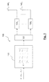
- the Fig. 5 represents a multi-antenna transmission system using a differential space-time code according to one embodiment of the invention.
- P 2 and the spatio-temporal code is given by (19).
- the system 500 can generally receive 2-bit words, the value of a bit giving a position PPM, for example 0 corresponds to the first position PPM and 1 corresponds to the second.
- the block of information symbols ⁇ k (s k, 1 , s k, 2 ) undergoes a coding operation in the differential space-time coder 510. More precisely, the coder 510 first determines the elements of the matrix S k by means of (25), then calculates the matrix C k from S k and C k-1 by means of the recurrence relation (23). The coefficients of the matrix C k-1 are stored in the delay element 525 to be available when coding the block ⁇ k .
- the 2 line 1 ⁇ 2 vectors of the first line of C k that is ( c k , 1.1 c k, 1.2 ), ( c k, 2.1 c k , 2.2 ) are respectively transmitted to the modulators UWB 530 1 and 530 2 via the multiplexer 520 to generate the first frame according to (29) and (30), then the 2 line 1 ⁇ 2 vectors of the first line of C k , of the second line of C k , that is ( c k, 2.2 c k, 2.1 ), ( c k, 1.1 c k, 1.2 ) to generate the second frames according to (31) and (32).
- the pulsed UWB signals thus modulated are then transmitted to the radiating elements 540 1 and 540 2 .
- These radiative elements may be UWB antennas or laser diodes or light-emitting diodes, operating for example in the infrared range, associated with electro-optical modulators.
- the UWB signals transmitted by the system illustrated in Fig. 5 can be processed by a single-antenna or multi-antenna receiver according to the invention which will now be described in connection with the Figure 6 .
- the receiver 600 comprises Q sensors 610, for example Q photoreceptors, or as shown here Q UWB receiving antennas.
- Each antenna (or sensor) is connected to a L-shaped 620 Rake filter to track the multi-path L of the propagation channel relating to that antenna.
- Y k is the transpose of Y k and S k is defined by (25), (26) or (27) according to the value of P.
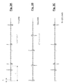
- the Fig. 7A gives the binary error rate (BER) curves as a function of the signal-to-noise ratio (SNR) for a UWB MIMO system using the spatio-temporal coding according to the invention with a propagation channel that does not introduce any interference between pulses.
- the separation between the two PMM positions is 100 ns, chosen larger than the UWB channel time delay (less than 100ns).
- the error rate curves for a MISO system with two transmit antennas (2 ⁇ 1), 720, and for a MISO system with four transmit antennas (4 ⁇ 1), 730 are shown. comparison is also shown in 710 the error rate curve for a conventional single-antenna system (1 ⁇ 1). In both cases, the gain in BER will be noted with respect to the conventional mono-antenna system.
- the Fig. 7B gives the bit error rate (BER) curves as a function of the signal-to-noise ratio (SNR) for a UWB MIMO system using the spatio-temporal coding according to the invention with a transmission channel. propagation introducing interference between pulses.
- the separation between the two PMM positions is 5 ns, less than the time delay of the UWB channel (less than 100ns).
- the error rate curve for a conventional single-antenna system (1 ⁇ 1) was also included in 715. It will be noted that in this case also a gain in BER is obtained with respect to the conventional mono-antenna system.
Abstract
Description
La présente invention concerne le domaine du codage spatio-temporel ou STC (Space Time Coding) pour des systèmes multi-antenne, notamment pour des applications en télécommunications ultra-large bande ou UWB (Ultra Wide Band).The invention relates to the field of space-time coding STC (Space Time Coding) for multi-antenna systems, particularly for applications in ultra-wideband, or UWB telecommunications (Ultra Wide Band).
Les systèmes de télécommunication sans fil de type multi-antenne sont bien connus de l'état de la technique. Ces systèmes utilisent une pluralité d'antennes à l'émission et/ou à la réception et sont dénommés, selon le type de configuration adoptée, MIMO (Multiple Input Multiple Output), MISO (Multiple Input Single Output) ou SIMO (Single Input Multiple Output). Par la suite nous emploierons le même terme MIMO pour couvrir les variantes MIMO et MISO précitées. L'exploitation de la diversité spatiale à l'émission et/ou à la réception permet à ces systèmes d'offrir des capacités de canal nettement supérieures à celles des systèmes mono-antenne classique (ou SISO pour Single Input Single Output). Cette diversité spatiale est généralement complétée par une diversité temporelle au moyen d'un codage spatio-temporel. Dans un tel codage, un symbole d'information à transmettre se trouve codé sur plusieurs antennes et plusieurs instants de transmission.Wireless telecommunication systems of the multi-antenna type are well known in the state of the art. These systems use a plurality of transmit and / or receive antennas and are called, according to the type of configuration adopted, Multiple Input Multiple Output (MIMO), Multiple Input Single Output (MISO) or Single Input Multiple (SIMO). Output ). Subsequently we will use the same term MIMO to cover the MIMO and MISO variants mentioned above. The use of space diversity on transmission and / or reception allows these systems to offer much higher channel capacities than conventional single-antenna systems (or SISOs for Single Input Single Output). This spatial diversity is generally supplemented by temporal diversity by means of spatio-temporal coding. In such coding, an information symbol to be transmitted is coded on several antennas and several times of transmission.
Un premier type de codes spatio-temporels est constitué par les codes STBC (Space Time Block Coding) ou codes par blocs.A first type of space-time codes consists of Space Time Block Coding (STBC) codes or block codes.
Dans un système multi-antenne utilisant un code par blocs, un bloc de symboles d'information à transmettre est codé en une matrice de symboles de transmission, une dimension de la matrice correspondant au nombre d'antennes et l'autre correspondant aux instants consécutifs de transmission.In a multi-antenna system using block code, a block of information symbols to be transmitted is encoded into a matrix of transmission symbols, one dimension of the matrix corresponding to the number of antennas and the other corresponding to the consecutive instants. of transmission.
La 
où les coefficients ct,p , t=1,..,T; p=1,..,P du code sont en règle générale des coefficients complexes dépendant des symboles d'information, P est le nombre d'antennes utilisées à l'émission, T est un entier indiquant l'extension temporelle du code, c'est-à-dire le nombre d'utilisations du canal ou PCUs (Per Channel Use). Un code spatio-temporel est dit réel si les coefficients c t,p sont réels, il est dit linéaire si la fonction de codage qui à tout bloc de symboles d'information σ associe la matrice spatio-temporelle C est linéaire.The
where the coefficients c t, p , t = 1, .., T ; p = 1, .., P of the code are as a rule complex coefficients depending on the information symbols, P is the number of antennas used on transmission, T is an integer indicating the temporal extension of the code, c that is the number of uses of the channel or PCUs ( Per Channel Use ). A spatio-temporal code is said to be real if the coefficients c t , p are real, it is said to be linear if the coding function which at any block of information symbols σ associates the spatio-temporal matrix C is linear.
Sur la
Le code spatio-temporel est caractérisé par son débit, c'est-à-dire par le nombre de symboles d'information qu'il transmet par instant d'utilisation de canal (PCU). Le code est dit à plein débit s'il est P fois plus élevé que le débit relatif à une utilisation mono-antenne (SISO). Un code est dit à débit unitaire s'il est identique à celui relatif à une utilisation mono-antenne.The spatio-temporal code is characterized by its bit rate, that is to say by the number of information symbols that it transmits per channel utilization time (PCU). The code is said to be full rate if it is P times higher than the relative bit rate for single-antenna use (SISO). A code is said unit rate if it is identical to that relating to a single-antenna use.
Le code spatio-temporel est caractérisé en outre par sa diversité qui peut être définie comme le rang de la matrice C. On aura une diversité maximale si pour deux mots de code C1 et C2 quelconques correspondant à deux vecteurs S1 et S2 , la matrice C1-C2 est de rang plein.The spatio-temporal code is further characterized by its diversity which can be defined as the rank of the matrix C. Maximum diversity will be obtained if for any two code words C 1 and C 2 corresponding to two vectors S 1 and S 2 , the C 1 -C 2 matrix is of full rank.
Le code spatio-temporel est enfin caractérisé par son gain de codage qui traduit la distance minimale entre différents mots du code. On peut le définir comme : 
ou, de manière équivalente, pour un code linéaire : 
or, equivalently, for a linear code:
Toutefois, le décodage des codes STBC se fait de manière cohérente, ce qui suppose généralement d'effectuer une estimation de canal à la réception, c'est-à-dire de déterminer la matrice H des coefficients complexes de propagation entre les antennes d'émission et les antennes de réception. Cette estimation de canal est rendue possible grâce à l'envoi de séquences de symboles pilote par le système de transmission, ce qui réduit d'autant la charge utile moyenne des blocs de symboles d'information. De surcroît, cette estimation doit être faite fréquemment dans les cas d'un canal de transmission présentant un faible rapport signal sur bruit ou des fluctuations rapides.However, the decoding of the STBC codes is done in a coherent manner, which generally assumes to perform a channel estimation on reception, that is to say to determine the matrix H of the complex propagation coefficients between the antennas. emission and receiving antennas. This channel estimation is made possible by sending pilot symbol sequences by the transmission system, thereby reducing the average payload of the information symbol blocks. In addition, this estimation must be made frequently in the case of a transmission channel with a low signal-to-noise ratio or rapid fluctuations.
Afin d'éviter de procéder à une estimation de canal, il a été proposé dans l'article de
Le codage spatio-temporel différentiel décrit dans les articles précités est limité au cas d'un système MISO avec P=2 antennes d'émission et des symboles d'information appartenant à une constellation de modulation PSK. A la différence d'un codage STBC classique, la matrice du code spatio-temporel différentiel pour un bloc donné dépend non seulement des symboles d'information de ce bloc mais également de la matrice du code spatio-temporel pour le bloc précédent. Plus précisément, si les blocs successifs de symboles d'information sont notés σ k où k est un indice temporel correspondant à un temps bloc, égal à deux temps symbole, la matrice du code Ck pour un bloc courant σ k =(σ1,k ,σ2,k ) est donnée par la relation de récurrence : 


Si l'on note r k,1 et r k,2 les scalaires correspondant aux signaux reçus par le récepteur respectivement pendant le premier temps symbole et le second temps symbole du bloc σ k et si l'on construit les matrices suivantes : 

où Tr(X) est la trace de la matrice X.If r k , 1 and r k , 2 denote the scalars corresponding to the signals received by the receiver respectively during the first symbol time and the second symbol time of the block σ k and if the following matrices are constructed:
where Tr ( X ) is the trace of the matrix X.
On remarquera que l'estimation de σ1,k ,σ2,k dans l'expression (6) ne fait pas intervenir la matrice H du canal de transmission.It will be noted that the estimation of σ 1, k , σ 2, k in expression (6) does not involve the matrix H of the transmission channel.
On a représenté en
Un autre domaine des télécommunications a récemment fait l'objet de recherches considérables. Il s'agit des systèmes de télécommunication UWB, pressentis notamment pour le développement des futurs réseaux personnels sans fil (WPAN). Ces systèmes ont pour spécificité de travailler directement en bande de base avec des signaux très large bande. On entend généralement par signal UWB un signal conforme au masque spectral stipulé dans la réglementation du FCC du 14 Février 2002 et révisé en Mars 2005, c'est-à-dire pour l'essentiel un signal dans la bande spectrale 3.1 à 10.6 GHz et présentant une largeur de bande d'au moins 500 MHz à -10dB. En pratique, on connaît deux types de signaux UWB, les signaux multi-bande OFDM (MB-OFDM) et les signaux UWB de type impulsionnel. Nous nous intéresserons par la suite uniquement à ces derniers.Another field of telecommunications has recently been the subject of considerable research. These are UWB telecommunication systems, which are being approached for the development of future wireless personal networks (WPAN). These systems have the specificity of working directly in baseband with very broadband signals. A UWB signal is generally understood to mean a signal conforming to the spectral mask stipulated in the FCC regulation of 14 February 2002 and revised in March 2005, that is to say essentially a signal in the 3.1 to 10.6 GHz spectral band and having a bandwidth of at least 500 MHz at -10dB. In practice, two types of UWB signals are known, the OFDM multi-band signals (MB-OFDM) and the UWB signals of impulse type. We will only be interested in them later.
Un signal UWB impulsionnel est constitué d'impulsions très courtes, typiquement de l'ordre de quelques centaines de picosecondes, réparties au sein d'une trame. Afin de réduire l'interférence multi-accès (MAI pour Multiple Access Interference), un code de sauts temporels (TH pour Time Hopping) distinct est affecté à chaque utilisateur. Le signal issu ou à destination d'un utilisateur k peut alors s'écrire sous la forme : 
On a représenté en 
Alternativement, les symboles d'information peuvent être transmis au moyen d'une modulation d'amplitude (PAM). Dans ce cas, le signal modulé peut s'écrire : 
Les modulations PPM et PAM peuvent aussi être combinées en une modulation composite M.M'-aire. Le signal modulé a alors la forme générale suivante : 
![]()
![]()
Au lieu de séparer les différents utilisateurs au moyen de codes de sauts temporels, il est également possible de les séparer par des codes orthogonaux, par exemple des codes de Hadamard, comme en DS-CDMA. On parle alors de DS-UWB (Direct Spread UWB). Dans ce cas on a pour l'expression du signal non modulé, correspondant à (7) : 
![]()
![]()
Comme précédemment, les symboles d'information peuvent être transmis au moyen d'une modulation PPM. Le signal DS-UWB modulé en position correspondant au signal TH-UWB (8) peut s'exprimer, en conservant les mêmes notations : 
Enfin, il est connu de combiner codes de sauts temporels et codes d'étalement spectral pour offrir des accès multiples aux différents utilisateurs. On obtient ainsi un signal UWB impulsionnel TH-DS-UWB de forme générale : 

Il est connu de l'état de la technique d'utiliser des signaux UWB dans des systèmes MIMO. Dans ce cas, chaque antenne transmet un signal UWB modulé en fonction d'un symbole d'information ou d'un bloc de tels symboles (STBC).It is known from the state of the art to use UWB signals in MIMO systems. In this case, each antenna transmits a UWB signal modulated according to an information symbol or a block of such symbols (STBC).
Il a été proposé dans l'article de 
où v(µ k,1) et v(µ k,2) sont des vecteurs de dimension M dont les composantes respectives sont δ(m - µ k,1), m = 0,...,M-1, et δ(m-µ k,2), m = 0,...,M-1. La matrice Ck du code est calculée au moyen des relations de récurrence : ![]()
![]()
où mod M signifie l'opération modulo M et 
where v (μ k, 1) and v (μ k, 2) are M-dimensional vectors whose respective components are δ (m - μ k, 1) m = 0, ..., M -1, and δ ( m- μk , 2 ), m = 0, ..., M -1. The matrix C k of the code is calculated by means of the recurrence relations: ![]()
![]()
where mod M means modulo operation M and
Les éléments du code spatio-temporel (15) sont des symboles dont les amplitudes respectives sont données par la relation de récurrence (16), et leurs positions PPM respectives par la relation de récurrence (17).The elements of the spatio-temporal code (15) are symbols whose respective amplitudes are given by the recurrence relation (16), and their respective positions PPM by the recurrence relation (17).
Dans le cas particulier de symboles d'information appartenant à un alphabet de modulation M-PPM, c'est-à-dire pour M'=0, les inversions de signe figurant dans les matrices (18) ont pour conséquence que les éléments du code spatio-temporel peuvent avoir des amplitudes négatives et par conséquent n'appartiennent pas à l'alphabet M-PPM. Il en résulte alors que les signaux UWB modulés par le code spatio-temporel contiennent des impulsions signées. Etant donné la très brève durée de ces impulsions et donc la très large bande des signaux UWB impulsionnels, il est excessivement difficile de récupérer une information de phase à la réception, et en particulier de détecter une inversion de signe. En outre, certains systèmes MIMO ne se prêtent pas ou mal à la transmission d'impulsions signées. Par exemple, les systèmes MIMO UWB optiques ne transmettent que des signaux d'intensité lumineuse TH-UWB, nécessairement dépourvus d'information de signe.In the particular case of information symbols belonging to a modulation alphabet M- PPM, that is to say for M ' = 0, the sign reversals appearing in the matrices (18) have the consequence that the elements of the Spatiotemporal code may have negative amplitudes and therefore do not belong to the M- PPM alphabet. As a result, the UWB signals modulated by the space-time code contain signed pulses. Given the very short duration of these pulses and therefore the very wide band of the UWB pulse signals, it is excessively difficult to recover a phase information on reception, and in particular to detect a sign reversal. In addition, some MIMO systems do not lend themselves to the transmission of signed pulses. For example, optical UWB MIMO systems only transmit TH-UWB light intensity signals, which are necessarily devoid of sign information.
L'objet de la présente invention est par conséquent de proposer un code spatio-temporel différentiel pour un système MIMO utilisant des signaux UWB impulsionnels ne faisant pas appel à la transmission d'impulsions signées. Un objet subsidiaire de la présente invention est de proposer un système de transmission MIMO UWB utilisant ledit code spatio-temporel, ainsi qu'un système de réception associé.The object of the present invention is therefore to propose a differential space-time code for a MIMO system using pulse UWB signals not involving the transmission of signed pulses. A subsidiary object of the present invention is to propose a UWB MIMO transmission system using said space-time code, as well as an associated reception system.
Selon un premier mode de réalisation, l'invention est définie par un procédé de codage spatio-temporel différentiel pour système de transmission UWB à deux éléments radiatifs, ledit procédé codant un bloc σ k=(sk,1,sk,2) de symboles d'information appartenant à un alphabet de modulation 2-PPM, en une séquence de deux vecteurs à deux composantes, les composantes d'un vecteur étant destinées à moduler en position un signal UWB impulsionnel pour un élément radiatif dudit système et une utilisation de canal de transmission donnés, chaque composante correspondant à une position de modulation PPM. Lesdits vecteurs sont obtenus à partir des éléments de la matrice de code : 
![]()
![]()

![]()
![]()
Selon un second mode de réalisation, l'invention est définie par un procédé de codage spatio-temporel différentiel pour système de transmission UWB à quatre éléments radiatifs, ledit procédé codant un bloc σ k=(sk,1,sk,2,sk,3,sk,4) de quatre symboles d'information appartenant à un alphabet de modulation 2-PPM, en une séquence de quatre vecteurs à deux composantes, les composantes d'un vecteur étant destinées à moduler en position un signal UWB impulsionnel pour un élément radiatif dudit système et une utilisation de canal de transmission donnés, chaque composante correspondant à une position de modulation PPM. Lesdits vecteurs sont obtenus à partir des éléments de la matrice de code : 
![]()
![]()

![]()
![]()
Selon un troisième mode de réalisation, l'invention est définie par un procédé de codage spatio-temporel différentiel pour système de transmission UWB à huit éléments radiatifs, ledit procédé codant un bloc σ k = (sk,1,sk,2,sk,3,sk,4,sk,5,sk,6,sk,7,sk,8) de huit symboles d'information appartenant à un alphabet de modulation 2-PPM, en une séquence de huit vecteurs à deux composantes, les composantes d'un vecteur étant destinées à moduler en position un signal UWB impulsionnel pour un élément radiatif dudit système et une utilisation de canal de transmission donnés, chaque composante correspondant à une position de modulation PPM. Lesdits vecteurs sont obtenus à partir des éléments de la matrice de code : 
![]()
![]()

![]()
![]()
L'invention concerne également un système de transmission UWB à deux éléments radiatifs, pour mettre en oeuvre le procédé selon le premier mode de réalisation. Ce système de transmission comprend :
- des moyens de codage pour coder un bloc σ k=(sk,1,sk,2) de deux symboles d'information appartenant à un alphabet de modulation 2-PPM, en une séquence de deux vecteurs à deux composantes, les composantes d'un vecteur étant destinées à moduler en position un signal UWB impulsionnel pour un élément radiatif dudit système et une utilisation de canal de transmission donnés, chaque composante correspondant à une position de modulation PPM, les moyens de codage obtenant lesdits vecteurs à partir des éléments de la matrice de code :


- deux modulateurs pour moduler en position un signal UWB impulsionnel, chaque modulateur étant associé à un élément radiatif et modulant en position ledit signal, pendant une utilisation du canal de transmission, à l'aide des composantes du vecteur associé au dit élément radiatif et à ladite utilisation du canal ;
- chaque élément radiatif étant adapté à émettre le signal ainsi modulé par ledit modulateur associé.
- encoding means for encoding a block σ k = (s k, 1 , s k, 2 ) of two information symbols belonging to a 2-PPM modulation alphabet, into a sequence of two two-component vectors, the components of a vector being intended to modulate in position a pulse UWB signal for a radiative element of said system and a given transmission channel utilization, each component corresponding to a PPM modulation position, the coding means obtaining said vectors from the elements of the code matrix:
- two modulators for modulating a pulse UWB signal in position, each modulator being associated with a radiative element and modulating in position said signal, during a use of the transmission channel, using the components of the vector associated with said radiative element and said use of the channel;
- each radiative element being adapted to emit the signal thus modulated by said associated modulator.
L'invention concerne également un système de transmission UWB à quatre éléments radiatifs, pour mettre en oeuvre le procédé selon le second mode de réalisation. Ce système de transmission comprend :
- des moyens de codage pour coder un bloc σ k=(sk,1,sk,2,sk,3,sk,4) de quatre symboles d'information appartenant à un alphabet de modulation 2-PPM, en une séquence de quatre vecteurs à deux composantes, les composantes d'un vecteur étant destinées à moduler en position un signal UWB impulsionnel pour un élément radiatif dudit système et une utilisation de canal de transmission donnés, chaque composante correspondant à une position de modulation PPM, les moyens de codage obtenant lesdits vecteurs à partir des éléments de la matrice de code :


- quatre modulateurs pour moduler en position un signal UWB impulsionnel, chaque modulateur étant associé à un élément radiatif et modulant en position ledit signal, pendant une utilisation du canal de transmission, à l'aide des composantes du vecteur associé au dit élément radiatif et à ladite utilisation du canal ;
- chaque élément radiatif étant adapté à émettre le signal ainsi modulé par ledit modulateur associé.
- encoding means for encoding a block σ k = (s k, 1 , s k, 2 , s k, 3 , s k, 4 ) of four information symbols belonging to a 2-PPM modulation alphabet, in one sequence of four two-component vectors, the components of a vector being intended to modulate in position a UWB pulse signal for an element radiative system of said system and a given transmission channel use, each component corresponding to a PPM modulation position, the coding means obtaining said vectors from the elements of the code matrix:
- four modulators for modulating a UWB pulse signal in position, each modulator being associated with a radiative element and modulating said signal in position during use of the transmission channel, using the components of the vector associated with said radiative element and said use of the channel;
- each radiative element being adapted to emit the signal thus modulated by said associated modulator.
L'invention concerne également un système de transmission UWB à huit éléments radiatifs, pour mettre en oeuvre le procédé selon le troisième mode de réalisation. Ce système de transmission comprend :
- des moyens de codage pour coder un bloc σ k=(sk,1,sk,2,sk,3,sk,4,sk,5,sk,6,sk,7,sk,8) de huit symboles d'information appartenant à un alphabet de modulation 2-PPM, en une séquence de huit vecteurs à deux composantes, les composantes d'un vecteur étant destinées à moduler en position un signal UWB impulsionnel pour un élément radiatif dudit système et une utilisation de canal de transmission donnés, chaque composante correspondant à une position de modulation PPM, les moyens de codage obtenant lesdits vecteurs à partir des éléments de la matrice de code :


- huit modulateurs pour moduler en position un signal UWB impulsionnel, chaque modulateur étant associé à un élément radiatif et modulant en position ledit signal, pendant une utilisation du canal de transmission, à l'aide des composantes du vecteur associé au dit élément radiatif et à ladite utilisation du canal ;
- chaque élément radiatif étant adapté à émettre le signal ainsi modulé par ledit modulateur associé.
- encoding means for coding a block σ k = (s k, 1 , s k, 2 , s k, 3 , s k, 4 , s k, 5 , s k, 6 , s k, 7 , s k, 8 ) of eight information symbols belonging to a 2-PPM modulation alphabet, in a sequence of eight two-component vectors, the components of a vector being intended to modulate in position a UWB pulse signal for a radiative element of said system and a given transmission channel utilization, each component corresponding to a PPM modulation position, the coding means obtaining said vectors from the elements of the code matrix:
- eight modulators for modulating a UWB pulse signal in position, each modulator being associated with a radiative element and modulating in position said signal, during a use of the transmission channel, using the components of the vector associated with said radiative element and said use of the channel;
- each radiative element being adapted to emit the signal thus modulated by said associated modulator.
Selon une première variante, les éléments radiatifs du système de transmission sont des antennes UWB. Selon une seconde variante, les éléments radiatifs du système de transmission sont des diodes laser ou des diodes électroluminescentes.According to a first variant, the radiative elements of the transmission system are UWB antennas. According to a second variant, the radiative elements of the transmission system are laser diodes or light-emitting diodes.
Ledit signal impulsionnel peut être un signal TH-UWB, un signal DS-UWB, ou un signal TH-DS-UWB.The said pulse signal may be a TH-UWB signal, a DS-UWB signal, or a TH-DS-UWB signal.
L'invention concerne enfin un système de réception UWB comportant une pluralité (Q') de capteurs destinés à recevoir un signal UWB impulsionnel transmis par un système de transmission tel que défini ci-dessus, dans lequel :
- chaque capteur est relié à un filtre Rake comprenant une pluralité (L) de doigts, chaque doigt suivant un multi-trajet du canal de propagation associé à ce capteur, chaque doigt q = 1,..,Q'L fournissant une valeur de variable de décision, yk,i,q,m , pour la m-ième position de modulation pendant le i-ième temps symbole du k-ième temps bloc ;
- un module de calcul recevant lesdites valeurs de variables de décision et calculant :
- pour chaque temps bloc k et chaque temps symbole i = 1,...,P, le vecteur ligne Yk,i défini par

- pour chaque temps bloc k, la matrice Yk de taille P×2QP, où P est le nombre d'antennes du système de transmission, définie par :
- Si P=2 :

- Si P=4 :

- Si P=8 :

- Si P=2 :
- pour chaque temps bloc k et chaque temps symbole i = 1,...,P, le vecteur ligne Yk,i défini par
- un module de détection estimant les P symboles d'information transmis pendant le temps bloc k par

si P=2, Sk est donnée par :
si P=4, Sk est une donnée par :
si P=8, Sk est donnée par :
- each sensor is connected to a Rake filter comprising a plurality ( L ) of fingers, each finger following a multipath of the propagation channel associated with this sensor, each finger q = 1, .., Q'L providing a variable value making, y k, i, q, m, for the m th position of the i th modulation during symbol time of the k th block time;
- a calculation module receiving said decision variable values and calculating:
- for each time block k and each symbol time i = 1, ..., P , the line vector Y k, i defined by
- for each time block k , the matrix Y k of size P × 2 QP , where P is the number of antennas of the transmission system, defined by:
- If P = 2:
- If P = 4:
- If P = 8:
- If P = 2:
- for each time block k and each symbol time i = 1, ..., P , the line vector Y k, i defined by
- a detection module estimating the P information symbols transmitted during the block time k by
if P = 2, S k is given by:
if P = 4, S k is a given by:
if P = 8, S k is given by:
Selon une première variante, les capteurs sont des antennes UWB. Selon une seconde variante, les capteurs sont des photodétecteurs.According to a first variant, the sensors are UWB antennas. According to a second variant, the sensors are photodetectors.
D'autres caractéristiques et avantages de l'invention apparaîtront à la lecture d'un mode de réalisation préférentiel de l'invention fait en référence aux figures jointes parmi lesquelles :
- la
Fig. 1 représente schématiquement un système de transmission MIMO utilisant un code STBC connu de l'état de la technique ; - la
Fig. 2 représente schématiquement un système de transmission MIMO utilisant un code spatio-temporel différentiel connu de l'état de la technique ; - les
Fig. 3A à 3C représentent les formes respectives de signaux TH-UWB, DS-UWB et TH-DS-UWB ; - la
Fig. 4 représente un alphabet de modulation M-PPM-M'-PPM ; - la
Fig. 5 représente schématiquement un système de transmission UWB multi-antenne selon un mode de réalisation de l'invention ; - la
Fig. 6 représente schématiquement un système de réception selon un mode de réalisation de l'invention ; - les
Figs 7A et7B montrent les courbes de taux d'erreur binaire en fonction du rapport signal sur bruit d'un système MIMO UWB impulsionnel selon l'invention, respectivement en absence et en présence d'interférence entre impulsions.
- the
Fig. 1 schematically represents a MIMO transmission system using an STBC code known from the state of the art; - the
Fig. 2 schematically represents a MIMO transmission system using a differential space-time code known from the state of the art; - the
Fig. 3A to 3C represent the respective forms of TH-UWB, DS-UWB and TH-DS-UWB signals; - the
Fig. 4 represents a modulation alphabet M -PPM- M ' -PPM; - the
Fig. 5 schematically shows a multi-antenna UWB transmission system according to one embodiment of the invention; - the
Fig. 6 schematically represents a reception system according to one embodiment of the invention; - the
Figs 7A and7B show the bit error rate curves as a function of the signal-to-noise ratio of a pulsed UWB MIMO system according to the invention, respectively in the absence and in the presence of interference between pulses.
L'idée à la base de l'invention est de concevoir un code spatio-temporel différentiel dont la diversité de codage est obtenue grâce à un opérateur de permutation agissant sur les positions de modulation de symboles d'information appartenant à un alphabet 2-PPM, dit aussi PPM binaire.The idea underlying the invention is to design a differential space-time code whose coding diversity is obtained thanks to a permutation operator acting on the information symbol modulation positions belonging to a 2-PPM alphabet. , also says binary PPM.
On considérera dans la suite un système de transmission UWB impulsionnel à P antennes de transmission et plus généralement, à P éléments radiatifs. Le code spatio-temporel utilisé par le système est défini par la matrice suivante, de dimension P × 2P,
- Pour P = 2 :

- Pour P = 4 :

- Pour P = 8 :


- For P = 2:
- For P = 4:
- For P = 8:
La matrice du code spatio-temporel différentiel Ck est obtenue par la relation de récurrence : 
![]()

![]()
Par exemple si la matrice 


La matrice Sk est fonction du bloc de symboles d'information σ k = (sk,1,sk,2,...,sk,P) où sk,p = (s k,p,1 s k,p,2) est un symbole 2-PPM égal à (1 0) lorsqu'il correspond à la première position de modulation et à (0 1) lorsqu'il correspond à la seconde position de modulation.The matrix S k is a function of the block of information symbols σ k = (s k, 1 , s k, 2 , ..., s k, P ) where s k, p = ( s k, p, 1 s k, p, 2 ) is a 2-PPM symbol equal to (1 0) when it corresponds to the first modulation position and (0 1) when it corresponds to the second modulation position.
Pour P=2, le bloc σ k comprend 2 symboles 2-PPM et Sk est un matrice de taille 4×4 donnée par : 
Pour P=4, le bloc σ k comprend 4 symboles 2-PPM et Sk est une matrice de taille 8×8 donnée par : 
Pour P=8, le bloc σ k comprend 8 symboles 2-PPM et Sk est une matrice de taille 16×16 donnée par : 
La matrice C0 , servant à initialiser la relation de récurrence (23) peut être donnée par l'expression (19), (20) ou (21) en choisissant des valeurs de symboles 2-PPM pour ck,1,...ck,P , par exemple ck,1 = ck,2 =...= ck,P =(1 0). Il est cependant clair pour l'homme du métier que d'autres valeurs de ck,1,...ck,P peuvent être également envisagées.The matrix C 0 , used to initialize the recurrence relation (23) can be given by the expression (19), (20) or (21) by choosing 2-PPM symbol values for c k, 1 , .. .c k, P , for example c k, 1 = c k, 2 = ... = c k, P = (1 0). However, it is clear to those skilled in the art that other values of c k, 1 , ... c k, P can also be envisaged.
On peut montrer que si la matrice Ck est de la forme (19), (20) ou (21) et Sk est respectivement de la forme (25), (26) ou (27), alors la matrice Ck+1 obtenue par la relation de récurrence (21) est encore bien de la forme (19), (20) ou (21). En outre, étant donné que les éléments de la matrice ![]()
![]()
![]()
![]()
Le code spatio-temporel Ck est à débit unitaire puisque P symboles d'information sont transmis pendant P utilisations du canal. On peut également montrer qu'il est à diversité maximale.The space-time code C k is at unit rate since P information symbols are transmitted during P uses of the channel. We can also show that it is at maximum diversity.
De manière générale, toute permutation sur les lignes (on entend ici par ligne, une ligne de vecteurs 1×2) et/ou les colonnes de Ck dans les expressions (19), (20), (21) est un code spatio-temporel selon l'invention, une permutation sur les lignes équivalant à une permutation des instants d'utilisation du canal (PCUs) et une permutation sur les colonnes équivalant à une permutation des antennes de transmission.In general, any permutation on the lines (here understood by line, a line of 1 × 2 vectors) and / or the columns of C k in the expressions (19), (20), (21) is a spatio code -Temporal according to the invention, a permutation on the lines equivalent to a permutation of the times of use of the channel (PCUs) and a permutation on the columns equivalent to a permutation of the transmission antennas.
A titre d'illustration, la matrice Ck peut être développée, par exemple pour P = 2: 
On supposera ici que le système utilise un signal TH-UWB, tel que défini en (7). Le code spatio-temporel différentiel module ce signal et le signal modulé est transmis pendant deux utilisations consécutives du canal (PCUs). Soit un bloc de symboles 2-PPM σ k=(sk,1,sk,2). Pendant la première utilisation du canal, la première antenne transmet une première trame, soit en reprenant les notations de (8) : 
où 0 et ε correspondent aux deux positions de modulation, et la seconde antenne transmet simultanément une première trame : 
Pendant la seconde utilisation du canal, la première antenne transmet une seconde trame : 

where 0 and ε correspond to the two modulation positions, and the second antenna simultaneously transmits a first frame:
During the second use of the channel, the first antenna transmits a second frame:
Comme on l'a vu plus haut c k,1,1, c k,1,2, c k,2,1 et c k,2,2 sont des valeurs égales à 0 ou 1 et n'introduisent par conséquent pas d'inversion de polarité ni d'amplification des impulsions. Ce code spatio-temporel se prête bien à la modulation d'un signal ultra-large bande.As discussed above c k, 1,1, c k, 1,2, c k, c k and 2.1, 2.2 are values equal to 0 or 1 and introduced by therefore no polarity reversal or pulse amplification. This space-time code lends itself well to the modulation of an ultra-wideband signal.
Il est clair pour l'homme du métier que l'on obtiendrait des expressions similaires en utilisant un signal DS-UWB selon l'expression (9) voire un signal DS-TH-UWB selon l'expression (10) au lieu d'un signal TH-UWB.It is clear to a person skilled in the art that similar expressions would be obtained by using a DS-UWB signal according to the expression (9) or even a DS-TH-UWB signal according to the expression (10) instead of a TH-UWB signal.
La
Le système 500 reçoit des blocs de 2 symboles d'information σ k=(sk,1,sk,2) où sk,1,sk,2 sont des symboles 2-PPM. Le système 500 peut de manière générale recevoir des mots de 2 bits, la valeur d'un bit donnant une position PPM, par exemple 0 correspond à la première position PPM et 1 correspond à la seconde.The
Le bloc de symboles d'information σ k=(sk,1,sk,2) subit une opération de codage dans le codeur spatio-temporel différentiel 510. Plus précisément, le codeur 510 détermine tout d'abord les éléments de la matrice Sk au moyen de (25), puis calcule la matrice Ck à partir de Sk et Ck-1 au moyen de la relation de récurrence (23). Les coefficients de la matrice Ck-1 sont mémorisés dans l'élément de retard 525 pour être disponible lors du codage du bloc σ k .The block of information symbols σ k = (s k, 1 , s k, 2 ) undergoes a coding operation in the differential space-
Les 2 vecteurs ligne 1×2 de la première ligne de C k, soit (c k,1,1 c k,1,2), (c k,2,1 c k,2,2) sont transmis respectivement aux modulateurs UWB 5301 et 5302 via le multiplexeur 520 pour générer les premières trame selon (29) et (30), puis les 2 vecteurs ligne 1×2 de la première ligne de Ck , de la seconde ligne de Ck , soit (c k,2,2 c k,2,1), (c k,1,1 c k,1,2) pour générer les secondes trames selon (31) et (32). Les signaux UWB impulsionnels ainsi modulés sont transmis ensuite aux éléments radiatifs 5401 et 5402. Ces éléments radiatifs peuvent être des antennes UWB ou bien des diodes laser ou encore des diodes électroluminescentes, fonctionnant par exemple dans le domaine infrarouge, associées à des modulateurs électro-optiques.The 2
Les signaux UWB transmis par le système illustré en
Le récepteur 600 comprend Q' capteurs 610, par exemple Q' photorécepteurs, ou comme représenté ici Q' antennes de réception UWB. Chaque antenne (ou capteur) est reliée à un filtre Rake 620 à L doigts pour suivre les L multi-trajets du canal de propagation relatif à cette antenne. Les Q=Q'L variables de décision en sortie des doigts des filtres Rake sont fournies à un module de calcul 630. Pour une antenne q' = 1,..,Q' donnée et un trajet ℓ = 1,..,L, on note yk,i,q,m la variable de décision fournie pour la m-ième position de modulation pendant le i-ième temps symbole du k-ième temps bloc, avec q=(q'-1)L+ℓ.The receiver 600 comprises
Le module de calcul 630 calcule tout d'abord, pour chaque temps bloc k et chaque temps symbole i = 1,..,P, les composantes des vecteur-lignes Yk,i , de taille 1×2Q définis par : 
Le module de calcul 630 construit ensuite la matrice Yk de taille P×2QP définie par :
- Si P = 2 :

- Si P = 4 :

- Si P = 8 :

- If P = 2:
- If P = 4:
- If P = 8:
A chaque temps bloc k, le module de calcul 630 transmet les éléments des matrices Yk,i , i = 1,..,P et Yk au module de détection 640. Le module de détection estime les symboles sk,1,sk,2,...,,sk,P du bloc σ k au moyen de la décision suivante : 
![]()
![]()
On remarquera qu'aucune des expressions (33) à (37) ne fait intervenir une estimation de canal de propagation, le décodage du code spatio-temporel se faisant uniquement à partir des valeurs des variables de décision yk,i,q,m .It will be noted that none of the expressions (33) to (37) involve a propagation channel estimate, the decoding of the spatio-temporal code being done solely from the values of the decision variables y k, i, q, m .
La
On a représenté les courbes de taux d'erreur pour un système MISO à deux antennes d'émission (2×1), 720, et pour un système MISO à quatre antennes d'émission (4×1), 730. A titre de comparaison on a également représenté en 710 la courbe de taux d'erreur pour un système classique mono-antenne (1×1). On remarquera dans les deux cas le gain en BER par rapport au système mono-antenne classique.The error rate curves for a MISO system with two transmit antennas (2 × 1), 720, and for a MISO system with four transmit antennas (4 × 1), 730 are shown. comparison is also shown in 710 the error rate curve for a conventional single-antenna system (1 × 1). In both cases, the gain in BER will be noted with respect to the conventional mono-antenna system.
La
On a représenté les courbes de taux d'erreur pour un système MISO à deux antennes d'émission (2×1), 725, et pour un système MIMO à deux antennes d'émission et deux antennes de réception (2×2), 735. A titre de comparaison on a également fait figurer en 715 la courbe de taux d'erreur pour un système classique mono-antenne (1×1). On remarquera que dans ce cas aussi on obtient un gain en BER par rapport au système mono-antenne classique.The error rate curves for a MISO system with two transmit antennas (2 × 1), 725, and for a MIMO system with two transmit antennas and two receive antennas (2 × 2), are shown. 735. For comparison, the error rate curve for a conventional single-antenna system (1 × 1) was also included in 715. It will be noted that in this case also a gain in BER is obtained with respect to the conventional mono-antenna system.
Claims (14)


Applications Claiming Priority (1)
| Application Number | Priority Date | Filing Date | Title |
|---|---|---|---|
| FR0851400A FR2928509B1 (en) | 2008-03-04 | 2008-03-04 | DIFFERENTIAL SPATIO-TEMPORAL ENCODING METHOD |
Publications (2)
| Publication Number | Publication Date |
|---|---|
| EP2099137A2 true EP2099137A2 (en) | 2009-09-09 |
| EP2099137A3 EP2099137A3 (en) | 2015-07-01 |
Family
ID=40029178
Family Applications (1)
| Application Number | Title | Priority Date | Filing Date |
|---|---|---|---|
| EP09153838.9A Withdrawn EP2099137A3 (en) | 2008-03-04 | 2009-02-27 | Differential spatial-temporal coding method |
Country Status (6)
| Country | Link |
|---|---|
| US (1) | US8194775B2 (en) |
| EP (1) | EP2099137A3 (en) |
| JP (1) | JP2009232453A (en) |
| KR (1) | KR20090095490A (en) |
| CN (1) | CN101527619B (en) |
| FR (1) | FR2928509B1 (en) |
Cited By (1)
| Publication number | Priority date | Publication date | Assignee | Title |
|---|---|---|---|---|
| CN102064915A (en) * | 2010-12-15 | 2011-05-18 | 西安交通大学 | Distributed differential space-time code transmission method suitable for fast fading channel |
Families Citing this family (10)
| Publication number | Priority date | Publication date | Assignee | Title |
|---|---|---|---|---|
| FR2927205A1 (en) * | 2008-01-31 | 2009-08-07 | Commissariat Energie Atomique | LOW PAPR SPATIO-TEMPORAL ENCODING METHOD FOR IMPULSE UWB TYPE MULTI-ANTENNA COMMUNICATION SYSTEM |
| JP5191971B2 (en) | 2009-10-06 | 2013-05-08 | ジヤトコ株式会社 | Vehicle oil pump control device |
| WO2012003061A1 (en) * | 2010-06-29 | 2012-01-05 | Rambus Inc. | Methods and systems for near-field mimo communication |
| WO2013129422A1 (en) * | 2012-03-02 | 2013-09-06 | 三菱電機株式会社 | Radio transmission device, radio reception device and data transmission method |
| WO2015045072A1 (en) * | 2013-09-26 | 2015-04-02 | 株式会社日立国際電気 | Wireless communication system and transmitter |
| CN107659520B (en) * | 2016-07-25 | 2021-07-02 | 苏州氶颂展览展示有限公司 | Signal modulation method and device |
| CN107894204B (en) | 2016-10-04 | 2020-02-21 | 财团法人工业技术研究院 | Interferometer and imaging method thereof |
| CN110741582A (en) * | 2017-06-15 | 2020-01-31 | 三菱电机株式会社 | Transmission device, reception device, and wireless communication system |
| JP7341980B2 (en) * | 2017-08-15 | 2023-09-11 | フラウンホッファー-ゲゼルシャフト ツァ フェルダールング デァ アンゲヴァンテン フォアシュンク エー.ファオ | wireless networks and equipment |
| CN109995404B (en) * | 2018-12-17 | 2021-06-01 | 郑州大学 | Differential modulation and demodulation method for space-frequency domain modulation |
-
2008
- 2008-03-04 FR FR0851400A patent/FR2928509B1/en not_active Expired - Fee Related
-
2009
- 2009-02-26 US US12/393,594 patent/US8194775B2/en not_active Expired - Fee Related
- 2009-02-27 EP EP09153838.9A patent/EP2099137A3/en not_active Withdrawn
- 2009-03-03 KR KR1020090018140A patent/KR20090095490A/en active IP Right Grant
- 2009-03-04 CN CN200910134688.1A patent/CN101527619B/en not_active Expired - Fee Related
- 2009-03-04 JP JP2009050382A patent/JP2009232453A/en active Pending
Non-Patent Citations (3)
| Title |
|---|
| C. ABOU-RJEILY ET AL.: "Differential space-time ultra- wideband communications", PROC. OF IEEE CONFERENCE ON ULTRA-WIDE BAND, September 2005 (2005-09-01), pages 248 - 253 |
| C. GAO ET AL.: "Bit error probability for space-time block code with coherent and differential detection", PROC. OF VEHICULAR TECHNOLOGY CONFERENCE, vol. 1, September 2002 (2002-09-01), pages 410 - 414 |
| V. TAROKH ET AL.: "A differential detection scheme for transmit diversity", IEEE JOURNAL ON SELECTED AREAS IN COMMUNICATIONS, vol. 18, no. 7, July 2000 (2000-07-01), pages 1169 - 1174 |
Cited By (2)
| Publication number | Priority date | Publication date | Assignee | Title |
|---|---|---|---|---|
| CN102064915A (en) * | 2010-12-15 | 2011-05-18 | 西安交通大学 | Distributed differential space-time code transmission method suitable for fast fading channel |
| CN102064915B (en) * | 2010-12-15 | 2013-05-22 | 西安交通大学 | Distributed differential space-time code transmission method suitable for fast fading channel |
Also Published As
| Publication number | Publication date |
|---|---|
| FR2928509B1 (en) | 2011-01-14 |
| US20090225809A1 (en) | 2009-09-10 |
| CN101527619B (en) | 2014-06-11 |
| JP2009232453A (en) | 2009-10-08 |
| US8194775B2 (en) | 2012-06-05 |
| KR20090095490A (en) | 2009-09-09 |
| FR2928509A1 (en) | 2009-09-11 |
| CN101527619A (en) | 2009-09-09 |
| EP2099137A3 (en) | 2015-07-01 |
Similar Documents
| Publication | Publication Date | Title |
|---|---|---|
| EP2099137A2 (en) | Differential spatial-temporal coding method | |
| EP2245751B1 (en) | Method of spatio-temporal coding with low papr for multi-antenna communication system of pulse uwb type | |
| EP2005608B1 (en) | Method of spatio-temporal coding for dual-antenna communication system of pulsed uwb type | |
| EP2070199B1 (en) | Method of spatio-temporal coding for multi-antenna communication system of pulsed uwb type | |
| EP1865613B1 (en) | UWB cooperative coherent communication system | |
| EP2026475A1 (en) | Space-time coding/decoding method for pulse type multi-antenna communication system | |
| EP1690361B1 (en) | Method for the multi-antenna transmission of a linearly-precoded signal, corresponding devices, signal and reception method | |
| EP1738513B1 (en) | Method for sending a signal in a multi-antenna system, corresponding signal and method for channel estimation | |
| EP2070238B1 (en) | Space-time encoding method for a multi-antenna communication system of the uwb pulse type | |
| FR2899745A1 (en) | SPATIO-TEMPORAL ENCODING METHOD FOR MULTI-ANTENNA COMMUNICATION SYSTEM OF IMPULSE UWB TYPE | |
| EP2122892B1 (en) | Method of spatio-temporal coding for multi-antenna communication system of pulsed uwb type | |
| EP1668794B1 (en) | Method for a multi-antenna transmission of a space-time block coded signal | |
| EP1852980A1 (en) | Non-coherent cooperative UWB communication system | |
| US20050135499A1 (en) | Differential space-time block coding apparatus using eight or less transmit antennas | |
| EP1995883A1 (en) | Scattered UWB MIMO communication system | |
| EP2053814B1 (en) | Space-time coding method using a divided position modulation alphabet | |
| WO2009095428A1 (en) | Optical mimo system |
Legal Events
| Date | Code | Title | Description |
|---|---|---|---|
| PUAI | Public reference made under article 153(3) epc to a published international application that has entered the european phase |
Free format text: ORIGINAL CODE: 0009012 |
|
| AK | Designated contracting states |
Kind code of ref document: A2 Designated state(s): AT BE BG CH CY CZ DE DK EE ES FI FR GB GR HR HU IE IS IT LI LT LU LV MC MK MT NL NO PL PT RO SE SI SK TR |
|
| AX | Request for extension of the european patent |
Extension state: AL BA RS |
|
| RAP1 | Party data changed (applicant data changed or rights of an application transferred) |
Owner name: COMMISSARIAT A L'ENERGIE ATOMIQUE ET AUX ENERGIES |
|
| PUAL | Search report despatched |
Free format text: ORIGINAL CODE: 0009013 |
|
| AK | Designated contracting states |
Kind code of ref document: A3 Designated state(s): AT BE BG CH CY CZ DE DK EE ES FI FR GB GR HR HU IE IS IT LI LT LU LV MC MK MT NL NO PL PT RO SE SI SK TR |
|
| AX | Request for extension of the european patent |
Extension state: AL BA RS |
|
| RIC1 | Information provided on ipc code assigned before grant |
Ipc: H04B 1/69 20110101AFI20150526BHEP Ipc: H04L 1/06 20060101ALI20150526BHEP Ipc: H04L 25/49 20060101ALI20150526BHEP |
|
| AKY | No designation fees paid | ||
| AXX | Extension fees paid |
Extension state: AL Extension state: RS Extension state: BA |
|
| REG | Reference to a national code |
Ref country code: DE Ref legal event code: R108 |
|
| STAA | Information on the status of an ep patent application or granted ep patent |
Free format text: STATUS: THE APPLICATION IS DEEMED TO BE WITHDRAWN |
|
| 18D | Application deemed to be withdrawn |
Effective date: 20160105 |