EP0668624B1 - Agencement de charge de puissance en hyperfréquence notamment pour dispositif guide d'ondes et isolateur à ferrite équipée d'un tel agencement - Google Patents
Agencement de charge de puissance en hyperfréquence notamment pour dispositif guide d'ondes et isolateur à ferrite équipée d'un tel agencement Download PDFInfo
- Publication number
- EP0668624B1 EP0668624B1 EP19950400324 EP95400324A EP0668624B1 EP 0668624 B1 EP0668624 B1 EP 0668624B1 EP 19950400324 EP19950400324 EP 19950400324 EP 95400324 A EP95400324 A EP 95400324A EP 0668624 B1 EP0668624 B1 EP 0668624B1
- Authority
- EP
- European Patent Office
- Prior art keywords
- wave guide
- arrangement according
- guide member
- load
- resonators
- Prior art date
- Legal status (The legal status is an assumption and is not a legal conclusion. Google has not performed a legal analysis and makes no representation as to the accuracy of the status listed.)
- Expired - Lifetime
Links
- 229910000859 α-Fe Inorganic materials 0.000 title claims description 3
- XLYOFNOQVPJJNP-UHFFFAOYSA-N water Substances O XLYOFNOQVPJJNP-UHFFFAOYSA-N 0.000 claims description 14
- 239000012212 insulator Substances 0.000 claims description 4
- 238000010521 absorption reaction Methods 0.000 claims description 3
- 230000000694 effects Effects 0.000 claims description 3
- 239000003989 dielectric material Substances 0.000 claims description 2
- 230000001131 transforming effect Effects 0.000 claims description 2
- 230000001902 propagating effect Effects 0.000 claims 1
- 230000005540 biological transmission Effects 0.000 description 9
- 239000000463 material Substances 0.000 description 3
- 239000004743 Polypropylene Substances 0.000 description 2
- 230000007423 decrease Effects 0.000 description 2
- 238000000034 method Methods 0.000 description 2
- -1 polypropylene Polymers 0.000 description 2
- 229920001155 polypropylene Polymers 0.000 description 2
- 238000004513 sizing Methods 0.000 description 2
- 229910052782 aluminium Inorganic materials 0.000 description 1
- XAGFODPZIPBFFR-UHFFFAOYSA-N aluminium Chemical compound [Al] XAGFODPZIPBFFR-UHFFFAOYSA-N 0.000 description 1
- 230000001419 dependent effect Effects 0.000 description 1
- 230000012010 growth Effects 0.000 description 1
- 238000005259 measurement Methods 0.000 description 1
- 229910052751 metal Inorganic materials 0.000 description 1
- 230000000644 propagated effect Effects 0.000 description 1
- 230000000717 retained effect Effects 0.000 description 1
- 229910001220 stainless steel Inorganic materials 0.000 description 1
- 239000010935 stainless steel Substances 0.000 description 1
Images

Classifications
-
- H—ELECTRICITY
- H01—ELECTRIC ELEMENTS
- H01P—WAVEGUIDES; RESONATORS, LINES, OR OTHER DEVICES OF THE WAVEGUIDE TYPE
- H01P1/00—Auxiliary devices
- H01P1/24—Terminating devices
- H01P1/26—Dissipative terminations
- H01P1/262—Dissipative terminations the dissipative medium being a liquid or being cooled by a liquid
Definitions
- the invention relates to a charging arrangement for microwave power, especially for devices waveguide, of the type described in the preamble to the claim 1.
- Load arrangements comprising resonators shifted in the direction of the axis of the waveguide element, from a distance as well relatively large, have the disadvantage of being bulky and require an adjustment device with a multitude of adapter screws and metallic elements localized to be used in a sufficiently wide frequency band but operating in a relatively temperature range low, significantly lower than the useful range 10 to 60 ° C.
- the object of the present invention is to provide a power load arrangement, which is compact and requires no adjustment in frequency and temperature ranges important imposed by the use which will be made of this arrangement.
- the arrangement according to the invention includes the features which are set out in the characterizing part of the claim 1.
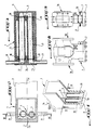
- Figure 1 is a perspective view, with breakout, power load arrangement according to the present invention.
- Figure 2 is a sectional view along line II-II of figure 1.
- Figure 3 is a sectional view along line III-III in Figure 2.
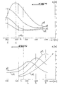
- Figure 4 shows four curves each representing at a temperature different from transmission losses of the adapted quadrupole of the larger water tube diameter, shown in the load arrangement according to Figures 1 to 3.
- Figure 5 is similar to Figure 4, but shows the four transmission loss curves of the quadrupole in the adapted state representing the water tube the smallest diameter of the load arrangement according to Figures 1 to 3.
- Figure 6 shows three curves each at a temperature different from the transmission losses of the quadrupole in the adapted state representing the two tubes of water from the charging arrangement according to FIGS. 1 to 3.
- Figure 7 shows four curves each representing at a different temperature the power rates in return of the load arrangement according to FIGS. 1 to 3, depending on the frequency.
- Figure 8 is a top view of an insulator equipped a charging arrangement according to the present invention.
- Figure 9 is a view in the direction of arrow 9 of Figure 8.
- the charging arrangement essentially comprises a waveguide element 1 closed at one end by a transverse wall 2 establishing a short circuit and open at its other end, configured to be connected to a waveguide device schematically indicated in 3, as well as the water charge 4.
- This device comprises two water tubes 6 and 7 of different diameters and connected at one end to one another by an internal channel 8 formed in a projection portion 9 of the waveguide element.
- the tubes are respectively connected to fittings 10 and 11, by means of internal channel portions 12 and 13 formed in another protrusion part 14 of the waveguide element.
- the two tubes 6 and 7 are slightly offset in the axis XX of the waveguide. This small difference is indicated by a . It optimizes the rate of return power in the useful frequency band and throughout the useful temperature range.
- tubes 6 and 7 are arranged at a short distance from the short-circuit wall 2 of the waveguide element 1.
- the planes transverse location of tubes 6 and 7 are at distances respectively b and c from this wall 2. These distances constitute setting parameters load arrangement point, as will be explained further.
- the two tubes are made of a material dielectric such as for example polypropylene.
- Each tube 6, 7 is dimensioned so that it behaves as a lossy dielectric waveguide, seats of several more or less coupled and resonant modes.
- the tubes have sections transverse circular, it is the choice of diameters tubes which is decisive for the invention.
- the invention is based on the fact that, under these conditions, the losses of the dielectric that constitutes the water filling the tubes vary as a function of the temperature and the diameter of the tubes. This phenomenon is clearly illustrated by FIGS. 4 and 5. These figures represent, for the tubes 6 and 7 respectively of larger and smaller diameter, the transmission losses P T as a function of the frequency F for the temperatures of 10, 23, 45 and 60 ° C. In each case the measurements were made by considering the tube 6 or 7 considered as a quadrupole. The losses were measured selectively for each of the tubes in the absence of the other. In each figure, the useful frequency band ⁇ F and the central frequency Fc of this band have been indicated on the abscissa.
- FIG. 4 which indicates the transmission losses P T measured thus for the tube of larger diameter 6, that the resonance frequencies F r of the four curves are lower than the central frequency F c so that the useful band ⁇ F is located on the right side of the downward slope of the resonance curves. It can also be seen that the resonance frequencies F r of the curves move away from the central frequency F c insofar as the temperature decreases, on the one hand, and, on the other hand, that the value of the vertex of the curves of reference increases with temperature. Considering the useful frequency band, the losses increase with temperature.
- a third tube could be placed between tube 6 and 7 and would allow increase the absorption losses of the charge.
- the invention is not limited when using cross-section tubes circular. On the contrary, it could be any other appropriate form.
- the invention is not also not limited to the use of tubes crossed by water. Indeed, one could employ elements in the shape of massive stems provided that the dielectric material constituting them has a high permittivity and sufficient loss factor.
- the load arrangement according to the invention as described above can be used in any application where it is a question of predicting at the exit of a waveguide track a load to absorb all the energy conveyed by this path.
- the Figures 8 and 9 illustrate the application of the invention to a monobloc ferrite insulator 16.
- the load arrangement is directly mounted in a path of a circulator by being integrated into its body, transforming this circulator into a load isolator integrated substantially without changing dimensions. This eliminates the assembly flange. We thus obtains a set having dimensions very reduced.
- the short circuit wall is formed by an attached wall element.
- the growths 9 and 11 can be produced in the form of added elements and produced in a material not attackable by water such as by example in stainless steel. Using seals 18 at the end of the tubes to prevent water from coming into contact with the material constituting the waveguide, such as aluminum.
Landscapes
- Non-Reversible Transmitting Devices (AREA)
- Constitution Of High-Frequency Heating (AREA)
Description
Claims (9)
- Agencement de charge de puissance en hyperfréquence, notamment pour dispositif guide d'ondes, du type comprenant un élément guide d'ondes (1) fermé à une extrémité par une paroi de court-circuit (2) et ouvert à l'autre qui est configurée pour être reliée audit dispositif guide d'ondes et un dispositif formant charge (4) en un matériau diélectrique à pertes, placé dans l'espace interne de l'élément guide d'ondes (1) à une certaine distance de la paroi de court-circuit, le dispositif de charge (4) étant configuré pour fonctionner en mode de résonance et comprenant au moins deux résonateurs (6,7) qui ont des pertes diélectriques différentes et sont placés dans l'élément guide d'ondes décalés l'un de l'autre dans la direction perpendiculaire à l'axe longitudinal de l'élément guide d'ondes (1), caractérisés en ce que les résonateurs (6, 7) sont disposés à une distance l'un de l'autre dans la direction de cet axe longitudinal, qui ne constitue au maximum qu'un faible décalage (a), et sont choisis de façon à présenter dans la bande de fréquence utile (ΔF) des variations de pertes en fonction de la température (T), de tendances inverses afin d'obtenir un effet de compensation de ces variations.
- Agencement selon la revendication 1, caractérisé en ce que le dispositif de charge (4) est placé à une distance prédéterminée de la paroi de court-circuit (2), qui est choisie de façon que la puissance réfléchie à l'entrée du dispositif de charge (4) et la puissance réfléchie par la paroi de court-circuit (2) soient en opposition de phase à ladite entrée.
- Agencement selon l'une des revendications 1 ou 2, caractérisé en ce que les résonateurs (6, 7) sont placés sensiblement dans un même plan perpendiculaire à l'axe de l'élément guide d'ondes (1).
- Agencement selon la revendication 1 ou 2, caractérisé en ce que les deux résonateurs sont inclinés par rapport à l'axe de l'élément guide d'ondes (1).
- Agencement selon l'une des revendications précédentes, caractérisé en ce que le dispositif de charge comprend, à titre de résonateurs, deux tubes d'eau (6 et 7) qui s'étendent perpendiculairement à l'axe longitudinal (X-X) de l'élément guide d'ondes (1) au moins approximativement dans un même plan tranversal et dont les diamètres sont différents et choisis pour obtenir les variations de pertes précitées de tendances inverses.
- Agencement selon la revendication 5, caractérisé en ce que les deux tubes (6 et 7) sont légèrement décalés dans l'axe (X-X) de l'élément guide d'ondes pour optimiser le taux de puissance en retour (RL) dans la bande de fréquences utile (ΔF) et dans toute la gamme de température utile.
- Agencement selon l'une des revendications précédentes, caractérisé en ce qu'il comprend au moins trois résonateurs disposés sensiblement dans un même plan transversal pour augmenter les pertes par absorption du dispositif de charge.
- Agencement selon l'une des revendications précédentes, caractérisé en ce que l'on prévoit au moins un deuxième réseau de résonateurs situé approximativement dans un même plan, à une distance d'un quart de la longueur d'onde de propagation du guide d'ondes, afin d'élargir la bande de fréquences utile.
- Isolateur à ferrite, caractérisé en ce que l'agencement de charge selon l'une des revendications 1 à 8 est directement monté dans une voie d'un circulateur en étant intégré à son corps, transformant ce circulateur en un isolateur à charge intégrée sensiblement sans chargement des dimensions.
Applications Claiming Priority (2)
| Application Number | Priority Date | Filing Date | Title |
|---|---|---|---|
| FR9401884 | 1994-02-18 | ||
| FR9401884A FR2716576B1 (fr) | 1994-02-18 | 1994-02-18 | Agencement de charge de puissance en hyperfréquence notamment pour dispositif guide d'ondes et isolateur à ferrite équipé d'un tel agencement. |
Publications (2)
| Publication Number | Publication Date |
|---|---|
| EP0668624A1 EP0668624A1 (fr) | 1995-08-23 |
| EP0668624B1 true EP0668624B1 (fr) | 2000-05-03 |
Family
ID=9460234
Family Applications (1)
| Application Number | Title | Priority Date | Filing Date |
|---|---|---|---|
| EP19950400324 Expired - Lifetime EP0668624B1 (fr) | 1994-02-18 | 1995-02-15 | Agencement de charge de puissance en hyperfréquence notamment pour dispositif guide d'ondes et isolateur à ferrite équipée d'un tel agencement |
Country Status (3)
| Country | Link |
|---|---|
| EP (1) | EP0668624B1 (fr) |
| DE (1) | DE69516560D1 (fr) |
| FR (1) | FR2716576B1 (fr) |
Families Citing this family (1)
| Publication number | Priority date | Publication date | Assignee | Title |
|---|---|---|---|---|
| RU2256259C2 (ru) * | 2003-07-11 | 2005-07-10 | ОАО "НИИ Приборостроения им. В.В. Тихомирова" | Волноводная нагрузка |
Family Cites Families (5)
| Publication number | Priority date | Publication date | Assignee | Title |
|---|---|---|---|---|
| FR1445906A (fr) * | 1965-08-24 | 1966-07-15 | Gen Electric | Perfectionnements aux charges absorbantes pour ondes ultracourtes |
| US3474354A (en) * | 1967-03-29 | 1969-10-21 | Us Navy | Multimode waveguide termination |
| GB1164945A (en) * | 1967-05-16 | 1969-09-24 | Ass Elect Ind | Improvements in or relating to Non-Reflective Waveguide Termination. |
| GB1372697A (en) * | 1970-11-21 | 1974-11-06 | Rotax Ltd | Waveguide |
| US3846720A (en) * | 1973-11-15 | 1974-11-05 | Bell Telephone Labor Inc | Compact microwave termination and uses thereof |
-
1994
- 1994-02-18 FR FR9401884A patent/FR2716576B1/fr not_active Expired - Fee Related
-
1995
- 1995-02-15 EP EP19950400324 patent/EP0668624B1/fr not_active Expired - Lifetime
- 1995-02-15 DE DE69516560T patent/DE69516560D1/de not_active Expired - Lifetime
Also Published As
| Publication number | Publication date |
|---|---|
| EP0668624A1 (fr) | 1995-08-23 |
| FR2716576B1 (fr) | 1996-05-03 |
| FR2716576A1 (fr) | 1995-08-25 |
| DE69516560D1 (de) | 2000-06-08 |
Similar Documents
| Publication | Publication Date | Title |
|---|---|---|
| FR3074364A1 (fr) | Charge interne pour tube a ondes progressives utilisant une ligne a retard en guide replie | |
| FR2992102A1 (fr) | Rail collecteur guide d'onde | |
| EP0014115B1 (fr) | Oscillateur accordable hyperfréquence à ondes magnétostatiques | |
| EP0201409A1 (fr) | Coupleur directif à large bande pour ligne à microruban | |
| FR2925230A1 (fr) | Dispositif d'amplification de puissance radiale a compensation de dispersion de phase des voies amplification | |
| FR2583597A1 (fr) | Filtre passe-bande hyperfrequences en mode evanescent | |
| EP3136499B1 (fr) | Système diviseur/combineur pour onde hyperféquence | |
| FR2850793A1 (fr) | Transition entre un circuit micro-ruban et un guide d'onde et unite exterieure d'emission reception incorporant la transition | |
| CH617556A5 (fr) | ||
| EP0467818B1 (fr) | Elément de transition entre guides d'ondes électromagnétiques, notamment entre un guide d'ondes circulaire et un guide d'ondes coaxial | |
| EP0377155B1 (fr) | Dispositif rayonnant bifréquence | |
| CA1260082A (fr) | Dispositif a joint tournant hyperfrequence | |
| EP0153541B1 (fr) | Fenêtre circulaire pour guide d'onde hyperfréquence | |
| EP0015610B1 (fr) | Filtre de réflexion de fréquence image en hyperfréquence et récepteur hyperfréquence comprenant un tel filtre | |
| FR2750816A1 (fr) | Source a resonateur dielectrique en mode de galerie | |
| EP0668624A1 (fr) | Agencement de charge de puissance en hyperfréquence notamment pour dispositif guide d'ondes et isolateur à ferrite équipée d'un tel agencement | |
| FR2813995A1 (fr) | Coupleur directionnel, dispositif d'antenne et systeme de radar | |
| FR2509536A1 (fr) | Filtre hyperfrequence comportant des couplages entre troncons de ligne et des moyens de reglage | |
| CA1074878A (fr) | Transition hyperfrequence | |
| EP0128798B1 (fr) | Dispositif sélectif accordable à ondes magnétostatiques de volume | |
| FR2755544A1 (fr) | Dispositif de filtrage a cavite metallique a inserts dielectriques | |
| FR2739974A1 (fr) | Lentille electromagnetique de type circuit imprime a substrat suspendu | |
| EP1925056B1 (fr) | Filtre a guide d'onde pour micro-ondes a parois non paralleles | |
| EP0369857A1 (fr) | Charge hyperfréquence en guide d'onde surdimensionné de faible longueur | |
| EP0274950A1 (fr) | Dispositif de couplage à large bande entre la ligne à retard d'un tube à onde progressive et le circuit externe de transmission de l'énergie du tube, et tube à onde progressive comportant un tel dispositif |
Legal Events
| Date | Code | Title | Description |
|---|---|---|---|
| PUAI | Public reference made under article 153(3) epc to a published international application that has entered the european phase |
Free format text: ORIGINAL CODE: 0009012 |
|
| AK | Designated contracting states |
Kind code of ref document: A1 Designated state(s): BE CH DE ES FR GB IT LI NL |
|
| 17P | Request for examination filed |
Effective date: 19960220 |
|
| 17Q | First examination report despatched |
Effective date: 19980520 |
|
| GRAG | Despatch of communication of intention to grant |
Free format text: ORIGINAL CODE: EPIDOS AGRA |
|
| GRAG | Despatch of communication of intention to grant |
Free format text: ORIGINAL CODE: EPIDOS AGRA |
|
| GRAH | Despatch of communication of intention to grant a patent |
Free format text: ORIGINAL CODE: EPIDOS IGRA |
|
| GRAH | Despatch of communication of intention to grant a patent |
Free format text: ORIGINAL CODE: EPIDOS IGRA |
|
| GRAA | (expected) grant |
Free format text: ORIGINAL CODE: 0009210 |
|
| AK | Designated contracting states |
Kind code of ref document: B1 Designated state(s): BE CH DE ES FR GB IT LI NL |
|
| PG25 | Lapsed in a contracting state [announced via postgrant information from national office to epo] |
Ref country code: NL Free format text: LAPSE BECAUSE OF FAILURE TO SUBMIT A TRANSLATION OF THE DESCRIPTION OR TO PAY THE FEE WITHIN THE PRESCRIBED TIME-LIMIT Effective date: 20000503 Ref country code: IT Free format text: LAPSE BECAUSE OF FAILURE TO SUBMIT A TRANSLATION OF THE DESCRIPTION OR TO PAY THE FEE WITHIN THE PRE;WARNING: LAPSES OF ITALIAN PATENTS WITH EFFECTIVE DATE BEFORE 2007 MAY HAVE OCCURRED AT ANY TIME BEFORE 2007. THE CORRECT EFFECTIVE DATE MAY BE DIFFERENT FROM THE ONE RECORDED.SCRIBED TIME-LIMIT Effective date: 20000503 Ref country code: GB Free format text: LAPSE BECAUSE OF FAILURE TO SUBMIT A TRANSLATION OF THE DESCRIPTION OR TO PAY THE FEE WITHIN THE PRESCRIBED TIME-LIMIT Effective date: 20000503 Ref country code: ES Free format text: THE PATENT HAS BEEN ANNULLED BY A DECISION OF A NATIONAL AUTHORITY Effective date: 20000503 |
|
| REG | Reference to a national code |
Ref country code: CH Ref legal event code: EP |
|
| REF | Corresponds to: |
Ref document number: 69516560 Country of ref document: DE Date of ref document: 20000608 |
|
| PG25 | Lapsed in a contracting state [announced via postgrant information from national office to epo] |
Ref country code: DE Free format text: LAPSE BECAUSE OF FAILURE TO SUBMIT A TRANSLATION OF THE DESCRIPTION OR TO PAY THE FEE WITHIN THE PRESCRIBED TIME-LIMIT Effective date: 20000804 |
|
| NLV1 | Nl: lapsed or annulled due to failure to fulfill the requirements of art. 29p and 29m of the patents act | ||
| GBV | Gb: ep patent (uk) treated as always having been void in accordance with gb section 77(7)/1977 [no translation filed] |
Effective date: 20000503 |
|
| PG25 | Lapsed in a contracting state [announced via postgrant information from national office to epo] |
Ref country code: LI Free format text: LAPSE BECAUSE OF NON-PAYMENT OF DUE FEES Effective date: 20010228 Ref country code: CH Free format text: LAPSE BECAUSE OF NON-PAYMENT OF DUE FEES Effective date: 20010228 Ref country code: BE Free format text: LAPSE BECAUSE OF NON-PAYMENT OF DUE FEES Effective date: 20010228 |
|
| PLBE | No opposition filed within time limit |
Free format text: ORIGINAL CODE: 0009261 |
|
| STAA | Information on the status of an ep patent application or granted ep patent |
Free format text: STATUS: NO OPPOSITION FILED WITHIN TIME LIMIT |
|
| 26N | No opposition filed | ||
| BERE | Be: lapsed |
Owner name: TEKELEC AIRTRONIC Effective date: 20010228 |
|
| REG | Reference to a national code |
Ref country code: CH Ref legal event code: PL |
|
| PG25 | Lapsed in a contracting state [announced via postgrant information from national office to epo] |
Ref country code: FR Free format text: LAPSE BECAUSE OF NON-PAYMENT OF DUE FEES Effective date: 20011031 |
|
| REG | Reference to a national code |
Ref country code: FR Ref legal event code: ST |