EP0668385B1 - Radially compressible cop for the winding of yarn - Google Patents
Radially compressible cop for the winding of yarn Download PDFInfo
- Publication number
- EP0668385B1 EP0668385B1 EP95100497A EP95100497A EP0668385B1 EP 0668385 B1 EP0668385 B1 EP 0668385B1 EP 95100497 A EP95100497 A EP 95100497A EP 95100497 A EP95100497 A EP 95100497A EP 0668385 B1 EP0668385 B1 EP 0668385B1
- Authority
- EP
- European Patent Office
- Prior art keywords
- rigid
- rods
- cop
- deformable
- tacks
- Prior art date
- Legal status (The legal status is an assumption and is not a legal conclusion. Google has not performed a legal analysis and makes no representation as to the accuracy of the status listed.)
- Expired - Lifetime
Links
- 238000004804 winding Methods 0.000 title description 12
- 230000008602 contraction Effects 0.000 claims description 19
- 230000002093 peripheral effect Effects 0.000 claims description 6
- 230000002787 reinforcement Effects 0.000 claims description 2
- 238000004043 dyeing Methods 0.000 description 12
- 239000007788 liquid Substances 0.000 description 6
- 238000010025 steaming Methods 0.000 description 5
- 238000005325 percolation Methods 0.000 description 3
- 238000004040 coloring Methods 0.000 description 2
- 230000000694 effects Effects 0.000 description 2
- 125000006850 spacer group Chemical group 0.000 description 2
- 238000005452 bending Methods 0.000 description 1
- 238000010438 heat treatment Methods 0.000 description 1
- 230000002452 interceptive effect Effects 0.000 description 1
- 239000000463 material Substances 0.000 description 1
- 239000007787 solid Substances 0.000 description 1
- 230000003313 weakening effect Effects 0.000 description 1
Images


Classifications
-
- D—TEXTILES; PAPER
- D06—TREATMENT OF TEXTILES OR THE LIKE; LAUNDERING; FLEXIBLE MATERIALS NOT OTHERWISE PROVIDED FOR
- D06B—TREATING TEXTILE MATERIALS USING LIQUIDS, GASES OR VAPOURS
- D06B23/00—Component parts, details, or accessories of apparatus or machines, specially adapted for the treating of textile materials, not restricted to a particular kind of apparatus, provided for in groups D06B1/00 - D06B21/00
- D06B23/04—Carriers or supports for textile materials to be treated
- D06B23/042—Perforated supports
- D06B23/045—Perforated supports radially collapsible
Definitions
- the present invention relates to a radially compressible cop for supporting a package of yarn. It relates more particularly to a cop suitable for supporting said yarn both during the steaming operation and during the subsequent dyeing operations.
- a first cop for steaming consisting of a cylindrical element having a lateral yarn winding wall which is solid and radially contractible when hot in order to adapt to the contraction which the yarn wound thereon undergoes during this operation, while for the subsequent dyeing operation it was necessary to use a different cop having a perforated lateral surface, suitable for the dye to pass through, in order to obtain uniform colouring of the yarn wound thereon.
- cops have been provided which are suitable for both operations. These cops comprise essentially a perforated lateral wall capable of contracting radially.
- Said cops are also housed for performing the abovementioned operations in autoclaves and stacked one on top of the other. They must therefore have a structure which, in addition to being radially contractable, is also sufficiently rigid and stable in order to withstand the considerable axial loads whereto it is subjected.
- Known radially collapsible perforated cops consist essentially of a cylindrical body for supporting yarn positioned between two end annular elements and which is defined by peripheral longitudinal rods which are all identical one to the other.
- Said longitudinal rods are essentially of two types: either they are rods which can be deformed in a transverse direction and are connected one to the other by rigid spacers, wherein the transverse deformation of the rods is provided by portions thereof which deform on the thrust of said rigid spacers, or they consist of rigid elements connected via intermediate deformable elements which themselves provide the radial contraction of the cop.
- said longitudinal rods consist of elements with a "V" section which deform in order to generate said radial contraction of the cop by the plastic rotation of the branches of said "V", or in other cases are connected by intermediate elements formed by deformable "V"'s.
- a further problem presented by known radial contraction cops for dyeing consists of the fact that the surface of winding of the yarn has the same diameter as the end flanges of the cop. This entails the risk that in parts the yarn detaches from the cop on which said yarn is wound loosely, via which the dye leaks longitudinally and does not therefore pass through the lateral surface of the cop, that is to say through the yarn, involving a loss of liquid intended for dyeing with subsequent decrease in dyeing efficiency and the risk of uneven colouring of the yarn.
- the object of the present invention is that of providing a cop for the winding of yarns which is radially compressible and has a structurally stable lateral surface with a sufficiently high percentage of holes to allow the passage of considerable quantities of the dyeing liquid.
- Another object of the present invention is that of providing a radially collapsible cop which avoids the risks of nipping of the yarn and risks of breakage of elements of the cop during the phase of contraction of the same.
- a further object of the present invention is that of providing a radially collapsible cop wherein the previous disadvantages of leakage or longitudinal percolation of the dyeing liquid have been eliminated.
- a radially compressible cop for supporting yarn consisting of a tubular body having a longitudinal axis and a lateral cylindrical surface for yarn winding positioned between two end annular elements, said tubular body comprising longitudinal peripheral rods for connecting said end annular elements defining said yarn collection surface, characterised in that said longitudinal peripheral rods comprise a first set of rigid rods arranged angularly equidistant one from the other and a second set of rods which can be deformed in their transverse direction and which are also angularly equidistant one from the other and arranged in a position intermediate to said rigid rods of said first set, and in that each deformable rod is connected to the adjacent rigid rod by means of rigid and circumferential stiffening tacks arranged longitudinally equidistant one from the other, with the rigid tacks originating from an adjacent rigid rod and which are arranged in a position intermediate to the rigid tacks originating from the opposite adjacent rigid rod.
- the fact of assigning the function of contraction only to a part of the elements forming the lateral winding surface allows, during the phase of radial contraction of said surface, stresses to be generated on the end flanges only in the areas of attachment of said deformable rods.
- the fact that said deformable rods are considerably distanced one from the other means that the stress which said deformable rods transmit due to the contraction at the end flanges can be distributed within said flanges without interfering with the stresses generated in the area of attachment by the other rods subjected to deformation, avoiding the risk of reaching maximum tensions which lead to the breakage of the attachment between said end annular elements and said longitudinal rods.
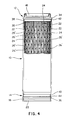
- Figures 1, 2 and 3 show a first preferred embodiment of the radially compressible cop according to the present invention. It comprises a tubular body 10 having a longitudinal axis and an external lateral cylindrical surface 11 for collecting the yarn and is between two end annular elements 12, 14.
- the cop also comprises a lower annular zone 16 for forming a yarn reserve, in a manner in itself known, and an upper ring 18 having an external diameter which corresponds to the internal diameter of a lower element 20 to allow the cop to be stacked.
- the tubular body 10 of the cop comprises, according to the invention, a double set of peripheral longitudinal rods which connect said annular elements 12, 14 and which define with their external face the surface 11 for winding the yarn.
- each deformable rod 24 is connected to the adjacent rigid rods 22 by means of stiffening parts or rigid tacks 26 arranged longitudinally equidistant one from the other in such a way that the rigid tacks 26 which originate from an adjacent rigid rod 22 are arranged in a position intermediate to the rigid tacks 26 which originate from the opposite adjacent rigid rod 22.
- the stiffening tacks 26 which connect a rigid rod 22 to an adjacent deformable rod 24 are on the extension of the tacks 26 which connect the same rigid rod 22 to the adjacent deformable rod 24 opposite the previous one.
- a tooth or stopping part 28 is also provided which, as is clear from Figure 3, forms an element for limiting radial contraction of said yarn collection surface. It allows the radial contraction of the winding surface of the cop to be controlled, allowing advantageously, in that it maintains said deformable rod 24, even after it has been deformed, detached from the adjacent rigid rod, a lateral winding surface to be obtained which has a considerable percentage of holes even in a collapsed condition.
- said stiffening tacks 26 and said stopping teeth 28 have an arched profile and an external surface which is recessed in relation to the external surface of said rods 22, 24 defining the yarn winding surface, in this way the risk for the former of these drawing the yarn in the contraction movement of the cop, and for the latter the risks of nipping the yarn during radial contraction are avoided.
- the cop is generally manufactured in a single moulded part of plastic material to form said rigid rods 22 and deformable rods 24, therefore it is sufficient to provide, as can be seen in Figure 2, the rigid rods 22 with a resistant section sufficiently greater than that of the deformable rods 24, for example providing rigid rods 22 with a section equal to approximately double that of the deformable rods 24.
- said end annular elements 12, 14 have been divided into a first end annular portion 34, 36 which has a specific external diameter, and into a second intermediate annular portion 38, 40 arranged between said first end annular portion and said cylindrical surface for collecting the yarn, which has a smaller external diameter than that of the first end annular portion, so that it is possible to deposit the yarn in contact with this second recessed annular portion and so that the annular step 42, 44 which separates said first annular portion from said second annular portion prevents further longitudinal percolation of the dyeing liquid.
- annular portions 38, 40 of the end annular elements 12, 14 intended for attachment of said longitudinal rods 22, 24 are provided with a smaller diameter or smaller thickness in order to be less rigid, means that these same portions 38, 40 can deform to follow the inflections of the deformable rods 24, so that for these too breakages of the attachment between rods 24 and end annular elements 12, 14 are avoided.
- said rigid tacks 26 are in the form of stems which have an enlarged reinforcement section 27 at the attachment of said tacks 26 with said rigid rods 22.
- a second preferred embodiment of the cop of the present invention is shown in Figure 4. It also comprises a tubular body 10 having a longitudinal axis and a lateral cylindrical surface for collection of the yarn between two end annular elements 12, 14.
- the tubular body 10 comprises, here too, a first set of rigid rods 22 arranged angularly equidistant one from the other and a second set of rods which can be deformed in their transverse direction 24 and are also angularly equidistant one from the other and arranged in positions intermediate to said rigid rods of said first set.
- Each deformable rod 24 is then connected to the adjacent rigid rods 22 by means of rigid transverse stiffening tacks 26' arranged longitudinally equidistant one from the other, with the rigid tacks 26' which originate from an adjacent rigid rod 22 and which are arranged in a position intermediate to the rigid tacks 26' of the opposite rigid rod 22.
- This second embodiment is distinguished from the first embodiment by the fact that it does not have the tack elements 26' which extend from the same rigid rod 22 towards the two adjacent deformable rods 24 which are on the same circumferential line but which are instead arranged spaced one from the other, and also by the fact that it has said tack elements 26' with convex lateral faces.
Landscapes
- Engineering & Computer Science (AREA)
- Textile Engineering (AREA)
- Treatment Of Fiber Materials (AREA)
- Storage Of Web-Like Or Filamentary Materials (AREA)
- Winding, Rewinding, Material Storage Devices (AREA)
- Looms (AREA)
Applications Claiming Priority (2)
| Application Number | Priority Date | Filing Date | Title |
|---|---|---|---|
| ITMI940145 | 1994-01-28 | ||
| ITMI940145A IT1269491B (it) | 1994-01-28 | 1994-01-28 | Tubetto radialmente comprimibile per l'avvolgimento di filati |
Publications (3)
| Publication Number | Publication Date |
|---|---|
| EP0668385A2 EP0668385A2 (en) | 1995-08-23 |
| EP0668385A3 EP0668385A3 (en) | 1996-03-27 |
| EP0668385B1 true EP0668385B1 (en) | 1998-06-24 |
Family
ID=11367674
Family Applications (1)
| Application Number | Title | Priority Date | Filing Date |
|---|---|---|---|
| EP95100497A Expired - Lifetime EP0668385B1 (en) | 1994-01-28 | 1995-01-16 | Radially compressible cop for the winding of yarn |
Country Status (5)
| Country | Link |
|---|---|
| US (1) | US5632451A (it) |
| EP (1) | EP0668385B1 (it) |
| DE (1) | DE69503076T2 (it) |
| ES (1) | ES2120639T3 (it) |
| IT (1) | IT1269491B (it) |
Families Citing this family (6)
| Publication number | Priority date | Publication date | Assignee | Title |
|---|---|---|---|---|
| US6367724B1 (en) * | 2000-06-09 | 2002-04-09 | Technimark, Inc. | Bi-directionally compressible dye tube |
| US6719230B2 (en) | 2002-01-29 | 2004-04-13 | Sonoco Development, Inc. | Collapsible yarn carrier tube |
| ITFI20030045U1 (it) * | 2003-04-22 | 2004-10-23 | Tiziano Romagnoli | Tubetto semirigido pervio in materiale plastico stampato, per bobine di filato destinato a trattamenti in tintoria |
| KR100617940B1 (ko) * | 2004-08-18 | 2006-09-04 | 손추익 | 치즈염색용 보빈 |
| US20080035783A1 (en) * | 2006-08-08 | 2008-02-14 | Couchey Brian P | Yarn carrier tube |
| CN107904835A (zh) * | 2017-11-24 | 2018-04-13 | 湖州新嘉怡丝织印花有限公司 | 一种筒子纱线染色用的可径向收缩塑料管 |
Family Cites Families (10)
| Publication number | Priority date | Publication date | Assignee | Title |
|---|---|---|---|---|
| NL162696C (nl) * | 1968-07-05 | 1980-06-16 | Zimmermann Fa Jos | Textielhuls, welke bij axiale samendrukking een gedwon- gen verkleining van de diameter tot gevolg heeft. |
| US3718287A (en) * | 1970-04-30 | 1973-02-27 | M Sottosanti | Collapsible spool |
| US3777515A (en) * | 1971-03-09 | 1973-12-11 | S Hattori | Synthetic resin bobbin |
| US3756532A (en) * | 1971-08-18 | 1973-09-04 | Albany Int Corp | Collapsible dye tube |
| FR2168682A5 (en) * | 1972-01-20 | 1973-08-31 | Sibille Rene Papeteries | Retractable tubular thread carrier - for uniform thread stabilisation, partic of synthetic fibres, prior to dyeing |
| CH564482A5 (it) * | 1973-04-03 | 1975-07-31 | Gretener Ag | |
| US4181274A (en) * | 1976-10-22 | 1980-01-01 | Burchette Robert L Jr | Dye tube |
| DE2828121A1 (de) * | 1978-06-27 | 1980-01-10 | Zimmermann Fa Jos | Wickeltraeger mit parallel zu seiner achse verlaufenden tragelementen |
| DE9011919U1 (de) * | 1990-08-17 | 1990-12-06 | Jos. Zimmermann GmbH & Co KG, 5100 Aachen | Schrumpfhülse |
| IT228192Y1 (it) * | 1992-08-28 | 1998-02-05 | Fabia Romagnoli | Tubetto a riduzione di diametro, in materiale plastico stampato ad iniezione per formare bobine di filato destinato alla tintoria ed |
-
1994
- 1994-01-28 IT ITMI940145A patent/IT1269491B/it active IP Right Grant
-
1995
- 1995-01-16 EP EP95100497A patent/EP0668385B1/en not_active Expired - Lifetime
- 1995-01-16 ES ES95100497T patent/ES2120639T3/es not_active Expired - Lifetime
- 1995-01-16 DE DE69503076T patent/DE69503076T2/de not_active Expired - Fee Related
- 1995-01-24 US US08/377,252 patent/US5632451A/en not_active Expired - Fee Related
Also Published As
| Publication number | Publication date |
|---|---|
| EP0668385A3 (en) | 1996-03-27 |
| EP0668385A2 (en) | 1995-08-23 |
| ITMI940145A1 (it) | 1995-07-28 |
| IT1269491B (it) | 1997-04-01 |
| ITMI940145A0 (it) | 1994-01-28 |
| ES2120639T3 (es) | 1998-11-01 |
| US5632451A (en) | 1997-05-27 |
| DE69503076T2 (de) | 1999-03-11 |
| DE69503076D1 (de) | 1998-07-30 |
Similar Documents
| Publication | Publication Date | Title |
|---|---|---|
| EP0668385B1 (en) | Radially compressible cop for the winding of yarn | |
| AU594285B2 (en) | Method of producing an endless sling | |
| US5480697A (en) | Structural part based on a sandwich fabric | |
| US3563491A (en) | Textile-treating sleeve | |
| JPS6338465B2 (it) | ||
| US4270710A (en) | Resiliently compressible bobbin | |
| US3714770A (en) | Inflatable gripper for handling spools of textile machines | |
| US4941621A (en) | Axially compressible spool | |
| US5445335A (en) | Coil carrier compressible in axial direction | |
| US2065526A (en) | Means for use in spinning and in liquid treating tubular rayon packages | |
| US3561696A (en) | Sleeve for treatment of textile threads and yarns | |
| NO170141B (no) | Pneumatisk dekk for kjoeretoeyhjul | |
| EP0469394B1 (en) | Axially compressible yarn windings waps tube | |
| US5131595A (en) | Axially deformable bobbin for dyeing spools | |
| US3561697A (en) | Or treatment of textile threads and yarns | |
| US2936964A (en) | Yarn supporting reel | |
| JP3048593U (ja) | 二重筒構造染色ボビン | |
| US4254962A (en) | Swab cup having long and short reinforcing members | |
| EP0536097B1 (en) | Interlocking dyeing support | |
| US20040211860A1 (en) | Pervious semi-rigid bobbin of molded plastics material for spools of yarn intended for treatments in dye works | |
| US3777515A (en) | Synthetic resin bobbin | |
| US4560116A (en) | Axially telescopic coil carrier parallel to each other | |
| US1992257A (en) | Spool | |
| JPS6220300B2 (it) | ||
| GB2195674A (en) | Device for straightening slantedly and/or arcuately distorted weft threads in a textile fabric |
Legal Events
| Date | Code | Title | Description |
|---|---|---|---|
| PUAI | Public reference made under article 153(3) epc to a published international application that has entered the european phase |
Free format text: ORIGINAL CODE: 0009012 |
|
| AK | Designated contracting states |
Kind code of ref document: A2 Designated state(s): CH DE ES FR GB GR LI |
|
| PUAL | Search report despatched |
Free format text: ORIGINAL CODE: 0009013 |
|
| AK | Designated contracting states |
Kind code of ref document: A3 Designated state(s): CH DE ES FR GB GR LI |
|
| 17P | Request for examination filed |
Effective date: 19960831 |
|
| GRAG | Despatch of communication of intention to grant |
Free format text: ORIGINAL CODE: EPIDOS AGRA |
|
| 17Q | First examination report despatched |
Effective date: 19970917 |
|
| GRAG | Despatch of communication of intention to grant |
Free format text: ORIGINAL CODE: EPIDOS AGRA |
|
| GRAH | Despatch of communication of intention to grant a patent |
Free format text: ORIGINAL CODE: EPIDOS IGRA |
|
| GRAH | Despatch of communication of intention to grant a patent |
Free format text: ORIGINAL CODE: EPIDOS IGRA |
|
| GRAA | (expected) grant |
Free format text: ORIGINAL CODE: 0009210 |
|
| AK | Designated contracting states |
Kind code of ref document: B1 Designated state(s): CH DE ES FR GB GR LI |
|
| PG25 | Lapsed in a contracting state [announced via postgrant information from national office to epo] |
Ref country code: LI Free format text: LAPSE BECAUSE OF FAILURE TO SUBMIT A TRANSLATION OF THE DESCRIPTION OR TO PAY THE FEE WITHIN THE PRESCRIBED TIME-LIMIT Effective date: 19980624 Ref country code: GR Free format text: LAPSE BECAUSE OF NON-PAYMENT OF DUE FEES Effective date: 19980624 Ref country code: CH Free format text: LAPSE BECAUSE OF FAILURE TO SUBMIT A TRANSLATION OF THE DESCRIPTION OR TO PAY THE FEE WITHIN THE PRESCRIBED TIME-LIMIT Effective date: 19980624 |
|
| REG | Reference to a national code |
Ref country code: CH Ref legal event code: EP |
|
| REF | Corresponds to: |
Ref document number: 69503076 Country of ref document: DE Date of ref document: 19980730 |
|
| REG | Reference to a national code |
Ref country code: ES Ref legal event code: FG2A Ref document number: 2120639 Country of ref document: ES Kind code of ref document: T3 |
|
| ET | Fr: translation filed | ||
| REG | Reference to a national code |
Ref country code: CH Ref legal event code: PL |
|
| PG25 | Lapsed in a contracting state [announced via postgrant information from national office to epo] |
Ref country code: GB Free format text: LAPSE BECAUSE OF NON-PAYMENT OF DUE FEES Effective date: 19990116 |
|
| PLBE | No opposition filed within time limit |
Free format text: ORIGINAL CODE: 0009261 |
|
| STAA | Information on the status of an ep patent application or granted ep patent |
Free format text: STATUS: NO OPPOSITION FILED WITHIN TIME LIMIT |
|
| 26N | No opposition filed | ||
| GBPC | Gb: european patent ceased through non-payment of renewal fee |
Effective date: 19990116 |
|
| PGFP | Annual fee paid to national office [announced via postgrant information from national office to epo] |
Ref country code: ES Payment date: 20010122 Year of fee payment: 7 |
|
| PGFP | Annual fee paid to national office [announced via postgrant information from national office to epo] |
Ref country code: FR Payment date: 20010126 Year of fee payment: 7 |
|
| PGFP | Annual fee paid to national office [announced via postgrant information from national office to epo] |
Ref country code: DE Payment date: 20010129 Year of fee payment: 7 |
|
| PG25 | Lapsed in a contracting state [announced via postgrant information from national office to epo] |
Ref country code: ES Free format text: LAPSE BECAUSE OF NON-PAYMENT OF DUE FEES Effective date: 20020117 |
|
| PG25 | Lapsed in a contracting state [announced via postgrant information from national office to epo] |
Ref country code: DE Free format text: LAPSE BECAUSE OF NON-PAYMENT OF DUE FEES Effective date: 20020801 |
|
| PG25 | Lapsed in a contracting state [announced via postgrant information from national office to epo] |
Ref country code: FR Free format text: LAPSE BECAUSE OF NON-PAYMENT OF DUE FEES Effective date: 20020930 |
|
| REG | Reference to a national code |
Ref country code: FR Ref legal event code: ST |
|
| REG | Reference to a national code |
Ref country code: ES Ref legal event code: FD2A Effective date: 20031122 |