EP0667279B1 - Actuator for steering rear wheels - Google Patents
Actuator for steering rear wheels Download PDFInfo
- Publication number
- EP0667279B1 EP0667279B1 EP95101225A EP95101225A EP0667279B1 EP 0667279 B1 EP0667279 B1 EP 0667279B1 EP 95101225 A EP95101225 A EP 95101225A EP 95101225 A EP95101225 A EP 95101225A EP 0667279 B1 EP0667279 B1 EP 0667279B1
- Authority
- EP
- European Patent Office
- Prior art keywords
- housing member
- disposed
- housing
- rotor
- internal space
- Prior art date
- Legal status (The legal status is an assumption and is not a legal conclusion. Google has not performed a legal analysis and makes no representation as to the accuracy of the status listed.)
- Expired - Lifetime
Links
- 239000011347 resin Substances 0.000 claims description 31
- 229920005989 resin Polymers 0.000 claims description 31
- 230000007246 mechanism Effects 0.000 claims description 19
- 238000006243 chemical reaction Methods 0.000 claims description 15
- 238000004519 manufacturing process Methods 0.000 claims description 7
- 230000002093 peripheral effect Effects 0.000 claims description 7
- 238000000034 method Methods 0.000 claims description 5
- XEEYBQQBJWHFJM-UHFFFAOYSA-N Iron Chemical compound [Fe] XEEYBQQBJWHFJM-UHFFFAOYSA-N 0.000 description 14
- BGPVFRJUHWVFKM-UHFFFAOYSA-N N1=C2C=CC=CC2=[N+]([O-])C1(CC1)CCC21N=C1C=CC=CC1=[N+]2[O-] Chemical compound N1=C2C=CC=CC2=[N+]([O-])C1(CC1)CCC21N=C1C=CC=CC1=[N+]2[O-] BGPVFRJUHWVFKM-UHFFFAOYSA-N 0.000 description 10
- 238000010276 construction Methods 0.000 description 10
- 238000000465 moulding Methods 0.000 description 10
- 230000009467 reduction Effects 0.000 description 8
- 229910052742 iron Inorganic materials 0.000 description 7
- 239000000463 material Substances 0.000 description 6
- 230000004048 modification Effects 0.000 description 6
- 238000012986 modification Methods 0.000 description 6
- 238000004804 winding Methods 0.000 description 5
- 238000003754 machining Methods 0.000 description 4
- 230000013011 mating Effects 0.000 description 4
- 230000015556 catabolic process Effects 0.000 description 2
- 238000006731 degradation reaction Methods 0.000 description 2
- 230000017525 heat dissipation Effects 0.000 description 2
- 238000010438 heat treatment Methods 0.000 description 2
- 230000007935 neutral effect Effects 0.000 description 2
- 230000004044 response Effects 0.000 description 2
- 229910052779 Neodymium Inorganic materials 0.000 description 1
- 239000004411 aluminium Substances 0.000 description 1
- XAGFODPZIPBFFR-UHFFFAOYSA-N aluminium Chemical compound [Al] XAGFODPZIPBFFR-UHFFFAOYSA-N 0.000 description 1
- 229910052782 aluminium Inorganic materials 0.000 description 1
- 238000006073 displacement reaction Methods 0.000 description 1
- 230000000694 effects Effects 0.000 description 1
- QEFYFXOXNSNQGX-UHFFFAOYSA-N neodymium atom Chemical compound [Nd] QEFYFXOXNSNQGX-UHFFFAOYSA-N 0.000 description 1
- 230000008569 process Effects 0.000 description 1
- 229910052761 rare earth metal Inorganic materials 0.000 description 1
Images




Classifications
-
- B—PERFORMING OPERATIONS; TRANSPORTING
- B62—LAND VEHICLES FOR TRAVELLING OTHERWISE THAN ON RAILS
- B62D—MOTOR VEHICLES; TRAILERS
- B62D5/00—Power-assisted or power-driven steering
- B62D5/04—Power-assisted or power-driven steering electrical, e.g. using an electric servo-motor connected to, or forming part of, the steering gear
- B62D5/0421—Electric motor acting on or near steering gear
- B62D5/0424—Electric motor acting on or near steering gear the axes of motor and final driven element of steering gear, e.g. rack, being parallel
- B62D5/0427—Electric motor acting on or near steering gear the axes of motor and final driven element of steering gear, e.g. rack, being parallel the axes being coaxial
-
- B—PERFORMING OPERATIONS; TRANSPORTING
- B62—LAND VEHICLES FOR TRAVELLING OTHERWISE THAN ON RAILS
- B62D—MOTOR VEHICLES; TRAILERS
- B62D5/00—Power-assisted or power-driven steering
- B62D5/04—Power-assisted or power-driven steering electrical, e.g. using an electric servo-motor connected to, or forming part of, the steering gear
- B62D5/0442—Conversion of rotational into longitudinal movement
- B62D5/0445—Screw drives
-
- H—ELECTRICITY
- H02—GENERATION; CONVERSION OR DISTRIBUTION OF ELECTRIC POWER
- H02K—DYNAMO-ELECTRIC MACHINES
- H02K5/00—Casings; Enclosures; Supports
- H02K5/04—Casings or enclosures characterised by the shape, form or construction thereof
-
- H—ELECTRICITY
- H02—GENERATION; CONVERSION OR DISTRIBUTION OF ELECTRIC POWER
- H02K—DYNAMO-ELECTRIC MACHINES
- H02K7/00—Arrangements for handling mechanical energy structurally associated with dynamo-electric machines, e.g. structural association with mechanical driving motors or auxiliary dynamo-electric machines
- H02K7/10—Structural association with clutches, brakes, gears, pulleys or mechanical starters
- H02K7/116—Structural association with clutches, brakes, gears, pulleys or mechanical starters with gears
-
- F—MECHANICAL ENGINEERING; LIGHTING; HEATING; WEAPONS; BLASTING
- F16—ENGINEERING ELEMENTS AND UNITS; GENERAL MEASURES FOR PRODUCING AND MAINTAINING EFFECTIVE FUNCTIONING OF MACHINES OR INSTALLATIONS; THERMAL INSULATION IN GENERAL
- F16H—GEARING
- F16H25/00—Gearings comprising primarily only cams, cam-followers and screw-and-nut mechanisms
- F16H25/18—Gearings comprising primarily only cams, cam-followers and screw-and-nut mechanisms for conveying or interconverting oscillating or reciprocating motions
- F16H25/20—Screw mechanisms
- F16H2025/2062—Arrangements for driving the actuator
- F16H2025/2087—Arrangements for driving the actuator using planetary gears
-
- Y—GENERAL TAGGING OF NEW TECHNOLOGICAL DEVELOPMENTS; GENERAL TAGGING OF CROSS-SECTIONAL TECHNOLOGIES SPANNING OVER SEVERAL SECTIONS OF THE IPC; TECHNICAL SUBJECTS COVERED BY FORMER USPC CROSS-REFERENCE ART COLLECTIONS [XRACs] AND DIGESTS
- Y10—TECHNICAL SUBJECTS COVERED BY FORMER USPC
- Y10T—TECHNICAL SUBJECTS COVERED BY FORMER US CLASSIFICATION
- Y10T74/00—Machine element or mechanism
- Y10T74/18—Mechanical movements
- Y10T74/18568—Reciprocating or oscillating to or from alternating rotary
- Y10T74/18576—Reciprocating or oscillating to or from alternating rotary including screw and nut
- Y10T74/18664—Shaft moves through rotary drive means
Definitions
- the invention relates to an actuator for steering rear wheels which may find its application in axially driving a steering shaft, by connection therewith, in order to assist a steering of an automobile, for example.
- an actuator for steering rear wheels of the kind described conventionally comprises an electric motor, a reduction gearing connected to the output from the motor, and a converter mechanism which transmits a rotary motion, outputted from the reduction gearing, to a steering shaft as converted into a linear motion.
- Such actuators are known in the art, as disclosed in Japanese Laid-Open Patent Applications No. 154,955/1985, No. 206,782/1985, No. 103,763/1988, No. 330,445/1993, and No. 330,446/1993 and Patent Publication No. 502,591/1992 (International Laid-Open No.: WO90/03,910).
- An actuator for driving rear wheels which is available in the art, is bulky in size and complex in construction, requiring time and labor for assembly during the manufacturing and thus resulting in a high manufacturing cost.
- the heating effect which occurs when the motor is driving is likely to cause a failure by a temperature rise inasmuch as a motor having a reduced size must be housed in an enclosed space of limited volume.
- an actuator for steering rear wheels constructed in accordance with the invention, comprising a housing member (1) which is cylindrically shaped, a cylindrical coil member (2) which is coaxially disposed within the internal space of the housing member, a support member (3) molded from resin integrally with the housing member and the coil member around the inner wall of the housing member for supporting the coil member in an integral manner with the housing member, a cylindrical rotor member (4) disposed in a space located inside the coil member and in a coaxial relationship with the housing member and rotatably supported by the support member through a bearing, a permanent magnet member (5) mounted on the rotor member, a drive shaft member (6) disposed so as to extend through a central space within the rotor member, an epicyclic gearing (7) disposed in an internal space of the housing member in coaxial relationship therewith and including a sun gear which is connected to the rotor member, a motion conversion mechanism (8) disposed in an internal space of the housing member in coaxial relationship therewith so as to be interposed between the epicycl
- one of bearings (10) which support the rotor member is disposed inside a mold so that the bearing is integrally secured to the support member.
- a ring gear (12) of the epicyclic gearing (7) may be formed around the part of the inner peripheral wall of the support member in accordance with the configuration of the mold used.
- a cylindrical coil member (2) is integrally secured, by a support member (3), formed of resin, in an internal space of a cylindrical housing member (1), and defines a stator of an electric motor.
- a cylindrical rotor member (4) is disposed inside the coil member, and is rotatably supported by the support member through a bearing.
- a permanent magnet member (5) is mounted on the rotor member at a location where it opposes the coil member, so that when the coil member is energized, a rotating force is exerted upon the rotor member, which therefore functions as a rotor of the electric motor.
- the rotating force from the rotor member is transmitted through an epicyclic gearing (7) including a sun gear which is connected therewith to a motion conversion mechanism (8), which converts the rotary motion into an axially linear motion, which is in turn transmitted to a drive shaft member (6).
- Magnetic pole detecting means (9) detects the location of a magnetic pole on the permanent magnet member, and accordingly, by switching the energization of the coil member on the basis of position data detected, the rotor member may be continuously and rotatively driven.
- a drive source (2, 4, 5), a reduction gearing (7), a conversion mechanism (8) and an output shaft (6) can all be disposed on a common shaft, dispensing with the provision of a separate member in order to provide a connection therebetween and allowing certain components to be shared, thus simplifying the construction and enabling a reduction in the size.
- the coil member which is a source of heat generated, is located outside the rotor, the heat from the coil member can be easily dissipated to the exterior through the housing member located adjacent thereto, thus preventing a significant temperature rise without requiring any additional space which is specially designed for heat dissipation. In this manner, the entire actuator can be reduced in size.
- the rotor can be formed in a small diameter, hence the inertia thereof is reduced, thus improving the response of the actuator.
- bearings (10) which support the rotor member (4) is disposed inside a mold so as to be integrally secured to the support member when the support member (3) is molded.
- a ring gear (12) of the epicyclic gearing (7) is preferably formed around a part of the internal peripheral wall of the support member in accordance with the configuration of the mold, thus eliminating the need for a ring gear as a separate part, thus reducing the number of parts and simplifying the assembly.
- the housing member is preferably formed with a recess (1a, 1b) or a projection in a region where it abuts against the support member.
- the molding operation produces a mating projection or mating recess on or in the support member, thus enabling a positive form-mating engagement therebetween.
- the housing member is cylindrical as is the outer peripheral surface of the support member which abuts against it, so that a slip is likely to occur in the rotational direction between the support member and the housing member depending on the rotating drive applied between the coil member and the rotor member.
- the form-mating engagement between the recess and the projection of the support member and the housing member prevents such slip from occurring.
- the actuator includes a casing 1, which is cylindrical and is formed of iron. To reduce the cost involved, the casing 1 is shaped by forming an iron pipe. Any other material which exhibits an excellent heat dissipating capability and which lends itself to a machining operation can be used other than an iron pipe.
- a pair of bearing members 15 and 16, formed of aluminium, are mounted in the casing 1 at the opposite ends thereof.
- An actuator shaft 6 extends through the casing 1 and is supported by the bearings 15, 16 so as to be axially movable.
- the actuator shaft 6 is formed with a groove 6x, which is engaged by a projection, not shown, which projects from the bearing member 15 to prevent a movement of the actuator shaft 6 in the angular direction.
- steering members for a rear left and a rear right wheel of an automobile are connected to the opposite ends of the actuator shaft 6, which is displaced axially to implement a steering of the rear wheels.
- a drive source for the actuator shaft 6 comprises an electric motor, which is internally housed within and integral with the actuator.
- the electric motor used in the present embodiment differs from a usual electric motor in that an electric coil 2 is disposed in the stator while a permanent magnet 5 is disposed on a rotor which is disposed inside the stator.
- the coil 2 comprises a three phase arrangement. The coil 2 generates a given moving magnetic field depending on the position of a magnetic pole on the permanent magnet 5, thereby rotatively driving the rotor which is integral with the permanent magnet 5.
- the electric coil 2 comprises a cylindrical sub-assembly having an outer diameter which is slightly less than the internal diameter of the casing 1, and is disposed inside the casing 1.
- a resin material 3 is molded integrally with the casing 1 and the coil 2.
- An anti-rotation lock for the resin material 3 is provided by projections 1c, 1d which are driven from the outside of the casing 1 and recesses 1a, 1b which are driven into the inside of the casing 1.
- the molding operation takes place. It will be seen that the coil 2 and the casing 1 are located close to each other with a thin layer of resin (3) interposed therebetween. This enables heat generated by the coil 2 to be easily transferred to the casing 1.
- a rotor of the electric motor comprises a cylindrical rotor member 4 formed of iron, a cylindrical permanent magnet 5 mounted around the outer periphery of the rotor member 4, and a power transmitting member 11.
- the opposite ends of the rotor are rotatably supported by bearings 10 and 17.
- the permanent magnet 5 comprises neodymium, a rare earth element, and is circumferentially formed with four magnetic poles as shown in Fig. 5.
- the permanent magnet 5 has an outer diameter which is slightly less than the internal diameter of the coil subassembly, and the inner diameter of the rotor member 4 is slightly greater than the outer diameter of the actuator shaft 6.
- the outer periphery of the bearing 10 is integrally secured to the casing 1 by means of the resin material 3 while the outer periphery of the bearing 17 is supported by a bearing member 16. Accordingly, the rotor is rotatable in an annular space disposed between the subassembly of the electric coil 2 and the actuator shaft 6, as indicated in Fig. 2.
- the power transmitting member 11 is formed into a substantially cylindrical configuration by resin, and is disposed coaxially with the rotor member 4 and is integrally secured to one end thereof. At its one end, the power transmitting member 11 is formed with a gear 11a around its outer periphery of a portion thereof which extends out of the rotor member 4.
- the gear 11a defines one of sun gears of an epicyclic gearing 7. Accordingly, when the motor is driven, the gear 11a of the power transmitting member 11 rotates to transmit the drive to the epicyclic gearing 7.
- the epicyclic gearing 7 comprises a pair of planetary gear trains connected in tandem.
- a first train comprises a gear (sun gear) 11a, planet gears 21, 22, 23 and 24, and a ring gear 12, as shown in Fig. 3.
- a second planetary gear train comprises a sun gear 29a, planet gears 31, 32, 33 and 34, and the ring gear 12, as shown in Fig. 4.
- the ring gear 12 is used in common between the pair of planetary gear trains, and is simultaneously molded as the resin member 3 is molded integrally with the casing 1.
- the planet gears 21, 22, 23 and 24 in the first train are rotatably mounted on individual shafts 25, 26, 27 and 28, respectively, which are fixedly mounted on a doughnut-shaped connecting plate 29, and the sun gear 29a in the second train is formed around a cylindrical projection located centrally on the connecting plate 29.
- the planet gears 31, 32, 33 and 34 in the second train are rotatably mounted on individual shafts 35, 36, 37 and 38, respectively, which are secured to a nut 41.
- the sun gear 11a which is integral therewith rotates, whereby the planet gears 21, 22, 23 and 24 in the first train revolve around the sun gear 11a to cause a rotation of the associated shafts 25 to 28 as well as its coupled connecting plate 29, whereby the sun gear 29a in the second train formed on the connecting plate 29 rotates to cause a revolution of the planet gears 31, 32, 33 and 34 in the second train around the sun gear 29a, causing a corresponding rotation of their associated shafts 35 to 38 and its coupled nut 41.
- the nut 41 is rotatably supported within the casing 1 by a bearing 42, but is immovable in the axial direction.
- the nut 41 is formed with trapezoidal threads 41a, which mesh with a mating trapezoidal screw 6a formed on the actuator shaft 6. Accordingly, as the nut 41 rotates, the trapezoidal screw 6a which is in meshing engagement with the trapezoidal threads 41a is displaced axially to cause an axial displacement of the actuator shaft 6.
- the combination of the nut 41 and the trapezoidal threads 6a defines a conversion mechanism 8 which converts a rotary motion of the epicyclic gearing 7 into a linear motion of the actuator shaft 6.
- the conversion mechanism may comprise a ball screw, in a modification as illustrated in Fig. 10.
- the rotor member 4 also carries another smaller permanent magnet 13 having magnetic poles formed thereon which are disposed in the same arrangement (see Fig. 5) as the magnetic poles on the permanent magnet 5.
- a Hall element 9 is disposed adjacent to the permanent magnet 13. Specifically, the Hall element 9 is fixedly mounted on the bearing member 16 which is integral with the casing 1. Accordingly, as the rotor member 4 rotates as does the magnetic poles of the permanent magnet 13, the Hall element 9 emits a pulse signal. The position of a magnetic pole on the rotor of the electric motor can be determined by referring to the pulse signal which is outputted from the Hall element 9.
- a potentiometer 43 is mounted on the bearing member 16, and includes a slider which engages a stub shaft 6b on the actuator shaft 6. In this manner, the potentiometer 43 detects an axial position of the actuator shaft 6 or the position to which the actuator is driven.
- the electric coil 2 is disposed on a given winding form to define a subassembly of the coil 2.
- the coil 2 is formed as an elliptical winding, as viewed in the cross section of Fig. 1.
- the subassembly is mounted on a mold A, not shown, and the bearing 10 is mounted on another mold B, not shown.
- the mold A is inserted into the cylindrical casing 1 from the right end thereof, as viewed in Fig. 1, while the mold B is inserted into the casing 1 from the left end thereof, and the coil 2 subassembly and the bearing 10 are positioned as indicated in Fig. 1.
- a molding resin is cast into a space or clearance defined or left by the casing 1, the mold A and the mold B, thus filling the clearance with the resin.
- the mold A and the mold B are removed from the casing 1.
- the mold B has an outer diameter which is slightly less than the inner diameter of the casing 1, and is formed with teeth around part of its periphery, whereby the ring gear 12 is molded around the inner wall (partly) of the resin member 3.
- the inner wall of the casing 1 is previously formed with the recesses 1a and 1b, into which the resin finds its way to form projections 3a and 3b in a manner corresponding to the recesses 1a and 1b around the outer periphery of the resin member 3. In this manner, a positive engagement between the recesses 1a, 1b and the projections 3a, 3b is achieved. Because the casing 1 is cylindrical in configuration, a simple molding of the resin member 3 will result in causing a slip between the resin member 3 and the casing 1, but the engagement between the recesses 1a, 1b and the projections 3a, 3b reliably prevents a relative movement or relative rotation therebetween.
- recesses 1a, 1b may be replaced by openings or holes, and alternatively that the casing 1 may be previously formed with projections.
- molds C and D are mounted on the rotor member 4, and a molding resin is injected into a clearance left therebetween (namely, a space corresponding to the power transmitting member 11).
- a gear (sun gear) 11a is formed around the outer periphery of the power transmitting member 11 at a location which extends out of the rotor member.
- the tip of the rotor member 4 is formed with an opening 4a, and accordingly, as a result of the molding operation, the power transmitting member 11 is formed with a projection 11b, which then engages the opening 4a in the rotor member 4 to provide a positive connection between the power transmitting member 11 and the rotor member 4. Subsequently, the cylindrical permanent magnet 5 and the annular permanent magnet 13 are fixedly mounted upon the rotor member 4.
- the nut 41 is mounted on the actuator shaft 6, the shafts 35, 36, 37 and 38 are mounted on the nut 41, and the planet gears 31, 32, 33 and 34 are mounted on the shafts 35, 36, 37 and 38, respectively.
- the connecting plate 29 is mounted on the actuator shaft 6, the shafts 25, 26, 27 and 28 are mounted on the connecting plate 29, and the planet gears 21, 22, 23 and 24 are mounted on the shafts 25, 26, 27 and 28, respectively.
- the coil 2 is disposed on one side of the casing 1 and since the casing 1 comprises an iron pipe and is separated from the coil 2 by a thin resin layer, an excellent heat dissipating capability is achieved even though the actuator itself is small in size. In addition, because the coil 2 does not rotate in operation, the inertia is reduced, allowing an increased output to be obtained for its size.
- the rotor does not rotate if the wheels are subject to forces applied from the road surface, thus achieving a null reverse efficiency.
- the described actuator is suitable for use in steering the rear wheels. If a ball screw is used for the conversion mechanism, a reverse efficiency will not be completely null, but a suitable gear ratio may be used for the epicyclic gearing so as to prevent any problem from occurring in the steering operation.
- FIG. 6 A modification of the actuator is shown in Fig. 6, and a region designated "VII" in Fig. 6 and corresponding to a connector portion is illustrated to an enlarged scale in Fig. 7.
- FIG. 8 A cross section taken along the line VIII-VIII shown in Fig. 7 is shown in Fig. 8.
- the construction of a connector VII is simplified as compared with the embodiment shown in Fig. 1, and the potentiometer which detects the position is replaced by a limit switch.
- a shaft 6 is provided with a step 6y, and as the drive position of the actuator crosses a neutral position, a limit switch LSW is switched, thus providing an indication of the neutral position.
- a limit switch LSW is switched, thus providing an indication of the neutral position.
- an L-shaped terminal T is exposed into an opening OP formed in the casing 1, allowing an attachment plug, not shown, to be inserted and fitted thereon from the outside for connection.
- Figs. 9 and 10 show another modification which utilizes a ball screw for the conversion mechanism.
- a drive source (2, 4, 5), a reduction gearing (7), a conversion mechanism (8) and an output shaft (6) can all be mounted on a common shaft, dispensing with a need to provide any separate member which provides a connection between respective mechanisms and also allowing certain parts to be shared by adjacent mechanisms.
- the construction is simplified, allowing a reduction in size.
- the winding member which generates heat is disposed outside the rotor, the heat generated by the winding member is easily transferred to the exterior through its adjacent housing member for dissipation, thus suppressing a temperature rise and avoiding the need to provide an additional space for purpose of heat dissipation.
- This also allows a reduction in the size of the overall actuator. Because the rotor can be made to a small diameter, the magnitude of inertia is reduced, improving the response of the actuator.
- one of the bearings (10) which support the rotor member (4) is disposed inside the mold to be secured integrally with the support member, again dispensing with the provision of a special member which is designed to fix the bearing and avoiding the need for a boring or a similar machining operation, again simplifying the construction and facilitating the assembly.
- the ring gear (12) of the epicyclic gearing (7) is formed around part of the inner peripheral wall of the support member in accordance with the configuration of the mold, dispensing with the need for a separate member which works as a ring gear and thus reducing the number of parts and facilitating the assembly.
- a portion of the housing member which abuts against the support member is formed with a recess (1a, 1b) or projection before the support member (3) is molded upon the housing member (1).
- This allows the molding operation to form a corresponding projection or recess to be formed in the support member to enable a positive engagement between the recess in (or projection on) the housing member and a mating projection on (or recess in) the support member.
- the housing member is cylindrical in accordance with the invention as is the outer peripheral surface of the support member which abuts against it, a rotating drive applied between the winding member and the rotor member may cause a slip in the rotational direction between the support member and the housing member, but the positive engagement between the recess and the projection formed in or on the support member and the housing member, respectively, prevents such slip from occurring.
- An actuator for steering rear wheels is reduced in size and its construction is simplified while preventing a degradation in the reliability.
- An electric coil 2 is disposed on the outside while a rotor is disposed on the inside, assisting in heating dissipation.
- One of bearings 10 which support a rotor and an electric coil 2 are integrally secured to a casing 1 when a resin 3 is molded thereon.
- a ring gear 12 is formed by the molding of the resin 3.
- the molding operation of the resin forms one of sun gears, 11a, integrally with a rotor 4.
- the casing 1 is formed with a recess or projection 1a, 1b, thus preventing a slip of the resin member 3 from occurring.
- a permanent magnet 13 which is separate from a permanent magnet 5 used for driving is mounted on the rotor.
Landscapes
- Engineering & Computer Science (AREA)
- Chemical & Material Sciences (AREA)
- Combustion & Propulsion (AREA)
- Transportation (AREA)
- Mechanical Engineering (AREA)
- Power Engineering (AREA)
- Power Steering Mechanism (AREA)
- Brushless Motors (AREA)
- Connection Of Motors, Electrical Generators, Mechanical Devices, And The Like (AREA)
Description
- The invention relates to an actuator for steering rear wheels which may find its application in axially driving a steering shaft, by connection therewith, in order to assist a steering of an automobile, for example.
- To realize a four wheel steering system for an automobile, for example, there is a need to provide an actuator for steering rear wheels which is operative to drive a steering shaft for the rear wheels in the axial direction thereof. To realize a high precision in controlling the steer angle, it is desirable to use such actuator which can be electrically driven.
- Accordingly, an actuator for steering rear wheels of the kind described conventionally comprises an electric motor, a reduction gearing connected to the output from the motor, and a converter mechanism which transmits a rotary motion, outputted from the reduction gearing, to a steering shaft as converted into a linear motion.
- Such actuators are known in the art, as disclosed in Japanese Laid-Open Patent Applications No. 154,955/1985, No. 206,782/1985, No. 103,763/1988, No. 330,445/1993, and No. 330,446/1993 and Patent Publication No. 502,591/1992 (International Laid-Open No.: WO90/03,910).
- Moreover, from DE-A-3836255 is known an actuator according to the preamble of
claim 1. - An actuator for driving rear wheels, which is available in the art, is bulky in size and complex in construction, requiring time and labor for assembly during the manufacturing and thus resulting in a high manufacturing cost. However, it is very difficult to reduce the size of such actuator. By way of example, while a reduction in the size of the electric motor is indispensable in order to reduce the size of such actuator, the heating effect which occurs when the motor is driving is likely to cause a failure by a temperature rise inasmuch as a motor having a reduced size must be housed in an enclosed space of limited volume.
- It is a task of the invention to reduce the size of an actuator for steering rear wheels, to simplify the construction thereof and to prevent a degradation in the reliability.
- Such task is met by an actuator for steering rear wheels constructed in accordance with the invention, comprising a housing member (1) which is cylindrically shaped, a cylindrical coil member (2) which is coaxially disposed within the internal space of the housing member, a support member (3) molded from resin integrally with the housing member and the coil member around the inner wall of the housing member for supporting the coil member in an integral manner with the housing member, a cylindrical rotor member (4) disposed in a space located inside the coil member and in a coaxial relationship with the housing member and rotatably supported by the support member through a bearing, a permanent magnet member (5) mounted on the rotor member, a drive shaft member (6) disposed so as to extend through a central space within the rotor member, an epicyclic gearing (7) disposed in an internal space of the housing member in coaxial relationship therewith and including a sun gear which is connected to the rotor member, a motion conversion mechanism (8) disposed in an internal space of the housing member in coaxial relationship therewith so as to be interposed between the epicyclic gearing and the drive shaft member for converting a rotary motion from the former into a linear motion in the axial direction of the latter, and magnetic pole detecting means (9) disposed in the internal space of the housing member for detecting the position of a magnetic pole on the permanent magnet member.
- In a preferred embodiment of the invention, when the support member is molded, one of bearings (10) which support the rotor member is disposed inside a mold so that the bearing is integrally secured to the support member.
- In another preferred embodiment of the invention, when the support member (3) is molded, a ring gear (12) of the epicyclic gearing (7) may be formed around the part of the inner peripheral wall of the support member in accordance with the configuration of the mold used.
- It is to be understood that numerals and characters appearing in parentheses in the above description denote reference numerals and characters which are used to designate corresponding parts used in an embodiment to be described later, but it should be understood that the components which are essential to construct the invention are not limited to specific elements shown in the embodiments.
- In accordance with the invention, a cylindrical coil member (2) is integrally secured, by a support member (3), formed of resin, in an internal space of a cylindrical housing member (1), and defines a stator of an electric motor. A cylindrical rotor member (4) is disposed inside the coil member, and is rotatably supported by the support member through a bearing. A permanent magnet member (5) is mounted on the rotor member at a location where it opposes the coil member, so that when the coil member is energized, a rotating force is exerted upon the rotor member, which therefore functions as a rotor of the electric motor. The rotating force from the rotor member is transmitted through an epicyclic gearing (7) including a sun gear which is connected therewith to a motion conversion mechanism (8), which converts the rotary motion into an axially linear motion, which is in turn transmitted to a drive shaft member (6). Magnetic pole detecting means (9) detects the location of a magnetic pole on the permanent magnet member, and accordingly, by switching the energization of the coil member on the basis of position data detected, the rotor member may be continuously and rotatively driven.
- With this construction, a drive source (2, 4, 5), a reduction gearing (7), a conversion mechanism (8) and an output shaft (6) can all be disposed on a common shaft, dispensing with the provision of a separate member in order to provide a connection therebetween and allowing certain components to be shared, thus simplifying the construction and enabling a reduction in the size. In particular, since the coil member, which is a source of heat generated, is located outside the rotor, the heat from the coil member can be easily dissipated to the exterior through the housing member located adjacent thereto, thus preventing a significant temperature rise without requiring any additional space which is specially designed for heat dissipation. In this manner, the entire actuator can be reduced in size. Finally, because the rotor can be formed in a small diameter, hence the inertia thereof is reduced, thus improving the response of the actuator.
- Preferably one of bearings (10) which support the rotor member (4) is disposed inside a mold so as to be integrally secured to the support member when the support member (3) is molded. This again dispenses with an addition of a special member or a boring operation or like machining in order to fix the bearing in position, thus contributing to simplifying the construction and facilitating the assembly.
- Also when the support member (3) is molded, a ring gear (12) of the epicyclic gearing (7) is preferably formed around a part of the internal peripheral wall of the support member in accordance with the configuration of the mold, thus eliminating the need for a ring gear as a separate part, thus reducing the number of parts and simplifying the assembly.
- In addition, when the support member (3) is molded upon the housing member (1), the housing member is preferably formed with a recess (1a, 1b) or a projection in a region where it abuts against the support member. The molding operation produces a mating projection or mating recess on or in the support member, thus enabling a positive form-mating engagement therebetween. It will be seen that in the construction of the invention, the housing member is cylindrical as is the outer peripheral surface of the support member which abuts against it, so that a slip is likely to occur in the rotational direction between the support member and the housing member depending on the rotating drive applied between the coil member and the rotor member. However, the form-mating engagement between the recess and the projection of the support member and the housing member prevents such slip from occurring.
-
- Fig. 1 is a longitudinal section of an actuator for steering rear wheels according to one embodiment of the invention;
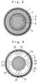
- Fig. 2 is a transverse section taken along the line II-II shown in Fig. 1;
- Fig. 3 is a transverse section taken along the line III-III shown in Fig. 1;
- Fig. 4 is a transverse section taken along the line IV-IV shown in Fig. 1;
- Fig. 5 is a fragmentary section illustrating a part of Fig. 2;
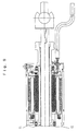
- Fig. 6 is a longitudinal section of a modification;
- Fig. 7 is a cross section to an enlarged scale, illustrating a portion designated VII" in Fig. 6;
- Fig. 8 is a transverse section taken along the line VIII-VIII shown in Fig. 7;
- Fig. 9 is a longitudinal section of part of a further modification; and
- Fig. 10 is a longitudinal section of remaining portion of Fig. 9.
- An actuator for steering rear wheels according to one embodiment of the invention is shown in longitudinal section in Fig. 1, and its transverse sections taken along the lines II-II, III-III and IV-IV shown in Fig. 1 are indicated in Figs. 2, 3 and 4, respectively. Initially referring to Fig. 1, the actuator includes a
casing 1, which is cylindrical and is formed of iron. To reduce the cost involved, thecasing 1 is shaped by forming an iron pipe. Any other material which exhibits an excellent heat dissipating capability and which lends itself to a machining operation can be used other than an iron pipe. A pair of bearingmembers casing 1 at the opposite ends thereof. Anactuator shaft 6 extends through thecasing 1 and is supported by thebearings actuator shaft 6 is formed with a groove 6x, which is engaged by a projection, not shown, which projects from the bearingmember 15 to prevent a movement of theactuator shaft 6 in the angular direction. - In general use, steering members for a rear left and a rear right wheel of an automobile are connected to the opposite ends of the
actuator shaft 6, which is displaced axially to implement a steering of the rear wheels. - A drive source for the
actuator shaft 6 comprises an electric motor, which is internally housed within and integral with the actuator. The electric motor used in the present embodiment differs from a usual electric motor in that anelectric coil 2 is disposed in the stator while apermanent magnet 5 is disposed on a rotor which is disposed inside the stator. Thecoil 2 comprises a three phase arrangement. Thecoil 2 generates a given moving magnetic field depending on the position of a magnetic pole on thepermanent magnet 5, thereby rotatively driving the rotor which is integral with thepermanent magnet 5. - The
electric coil 2 comprises a cylindrical sub-assembly having an outer diameter which is slightly less than the internal diameter of thecasing 1, and is disposed inside thecasing 1. After thecoil 2 is placed inside thecasing 1, aresin material 3 is molded integrally with thecasing 1 and thecoil 2. An anti-rotation lock for theresin material 3 is provided byprojections 1c, 1d which are driven from the outside of thecasing 1 andrecesses casing 1. After thecoil 2 is positioned by theprojections 1c, 1d in a left-and-right direction, as viewed in the drawings, the molding operation takes place. It will be seen that thecoil 2 and thecasing 1 are located close to each other with a thin layer of resin (3) interposed therebetween. This enables heat generated by thecoil 2 to be easily transferred to thecasing 1. - On the other hand, a rotor of the electric motor comprises a
cylindrical rotor member 4 formed of iron, a cylindricalpermanent magnet 5 mounted around the outer periphery of therotor member 4, and a power transmitting member 11. The opposite ends of the rotor are rotatably supported bybearings 10 and 17. Thepermanent magnet 5 comprises neodymium, a rare earth element, and is circumferentially formed with four magnetic poles as shown in Fig. 5. Thepermanent magnet 5 has an outer diameter which is slightly less than the internal diameter of the coil subassembly, and the inner diameter of therotor member 4 is slightly greater than the outer diameter of theactuator shaft 6. The outer periphery of the bearing 10 is integrally secured to thecasing 1 by means of theresin material 3 while the outer periphery of thebearing 17 is supported by a bearingmember 16. Accordingly, the rotor is rotatable in an annular space disposed between the subassembly of theelectric coil 2 and theactuator shaft 6, as indicated in Fig. 2. - The power transmitting member 11 is formed into a substantially cylindrical configuration by resin, and is disposed coaxially with the
rotor member 4 and is integrally secured to one end thereof. At its one end, the power transmitting member 11 is formed with agear 11a around its outer periphery of a portion thereof which extends out of therotor member 4. Thegear 11a defines one of sun gears of an epicyclic gearing 7. Accordingly, when the motor is driven, thegear 11a of the power transmitting member 11 rotates to transmit the drive to the epicyclic gearing 7. - The epicyclic gearing 7 comprises a pair of planetary gear trains connected in tandem. A first train comprises a gear (sun gear) 11a, planet gears 21, 22, 23 and 24, and a
ring gear 12, as shown in Fig. 3. A second planetary gear train comprises a sun gear 29a, planet gears 31, 32, 33 and 34, and thering gear 12, as shown in Fig. 4. Thering gear 12 is used in common between the pair of planetary gear trains, and is simultaneously molded as theresin member 3 is molded integrally with thecasing 1. - The planet gears 21, 22, 23 and 24 in the first train are rotatably mounted on
individual shafts plate 29, and the sun gear 29a in the second train is formed around a cylindrical projection located centrally on the connectingplate 29. The planet gears 31, 32, 33 and 34 in the second train are rotatably mounted onindividual shafts nut 41. - Accordingly, when the
rotor member 4 rotates, thesun gear 11a which is integral therewith rotates, whereby the planet gears 21, 22, 23 and 24 in the first train revolve around thesun gear 11a to cause a rotation of the associatedshafts 25 to 28 as well as its coupled connectingplate 29, whereby the sun gear 29a in the second train formed on the connectingplate 29 rotates to cause a revolution of the planet gears 31, 32, 33 and 34 in the second train around the sun gear 29a, causing a corresponding rotation of their associatedshafts 35 to 38 and its couplednut 41. - The
nut 41 is rotatably supported within thecasing 1 by abearing 42, but is immovable in the axial direction. Thenut 41 is formed withtrapezoidal threads 41a, which mesh with amating trapezoidal screw 6a formed on theactuator shaft 6. Accordingly, as thenut 41 rotates, thetrapezoidal screw 6a which is in meshing engagement with thetrapezoidal threads 41a is displaced axially to cause an axial displacement of theactuator shaft 6. In other words, the combination of thenut 41 and thetrapezoidal threads 6a defines aconversion mechanism 8 which converts a rotary motion of the epicyclic gearing 7 into a linear motion of theactuator shaft 6. It is to be noted that the conversion mechanism may comprise a ball screw, in a modification as illustrated in Fig. 10. - At a location spaced from the
permanent magnet 5, therotor member 4 also carries another smallerpermanent magnet 13 having magnetic poles formed thereon which are disposed in the same arrangement (see Fig. 5) as the magnetic poles on thepermanent magnet 5. A Hall element 9 is disposed adjacent to thepermanent magnet 13. Specifically, the Hall element 9 is fixedly mounted on the bearingmember 16 which is integral with thecasing 1. Accordingly, as therotor member 4 rotates as does the magnetic poles of thepermanent magnet 13, the Hall element 9 emits a pulse signal. The position of a magnetic pole on the rotor of the electric motor can be determined by referring to the pulse signal which is outputted from the Hall element 9. - A
potentiometer 43 is mounted on the bearingmember 16, and includes a slider which engages astub shaft 6b on theactuator shaft 6. In this manner, thepotentiometer 43 detects an axial position of theactuator shaft 6 or the position to which the actuator is driven. - A process of manufacturing the actuator of the above embodiment will now be described. The
electric coil 2 is disposed on a given winding form to define a subassembly of thecoil 2. In the present example, thecoil 2 is formed as an elliptical winding, as viewed in the cross section of Fig. 1. - The subassembly is mounted on a mold A, not shown, and the bearing 10 is mounted on another mold B, not shown. The mold A is inserted into the
cylindrical casing 1 from the right end thereof, as viewed in Fig. 1, while the mold B is inserted into thecasing 1 from the left end thereof, and thecoil 2 subassembly and the bearing 10 are positioned as indicated in Fig. 1. - A molding resin is cast into a space or clearance defined or left by the
casing 1, the mold A and the mold B, thus filling the clearance with the resin. When the resin is set, the mold A and the mold B are removed from thecasing 1. - As a result, the
resin material 3 is molded into a hardened piece, and at the same time thecoil assembly 2 and the bearing 10 are secured within thecasing 1 by means of theresin material 3. The mold B has an outer diameter which is slightly less than the inner diameter of thecasing 1, and is formed with teeth around part of its periphery, whereby thering gear 12 is molded around the inner wall (partly) of theresin member 3. - As shown in Figs. 1 and 4, the inner wall of the
casing 1 is previously formed with therecesses projections recesses resin member 3. In this manner, a positive engagement between therecesses projections casing 1 is cylindrical in configuration, a simple molding of theresin member 3 will result in causing a slip between theresin member 3 and thecasing 1, but the engagement between therecesses projections - In a similar manner, since the inner wall of the
casing 1 is previously formed withprojections 1c, 1d, resin define recesses 3c, 3d around the outer periphery of theresin member 3 which correspond to theprojections 1c and 1d. Again, a positive engagement between theprojections 1c, 1d and the recesses 3c, 3d is achieved, reliably preventing a relative movement or relative rotation therebetween. - It will be noted that the
recesses casing 1 may be previously formed with projections. - When producing a rotor subassembly, molds C and D, both not shown, are mounted on the
rotor member 4, and a molding resin is injected into a clearance left therebetween (namely, a space corresponding to the power transmitting member 11). When the resin is set, the power transmitting member 11 is formed. During the molding operation, a gear (sun gear) 11a is formed around the outer periphery of the power transmitting member 11 at a location which extends out of the rotor member. The tip of therotor member 4 is formed with an opening 4a, and accordingly, as a result of the molding operation, the power transmitting member 11 is formed with aprojection 11b, which then engages the opening 4a in therotor member 4 to provide a positive connection between the power transmitting member 11 and therotor member 4. Subsequently, the cylindricalpermanent magnet 5 and the annularpermanent magnet 13 are fixedly mounted upon therotor member 4. - Subsequently, the
nut 41 is mounted on theactuator shaft 6, theshafts nut 41, and the planet gears 31, 32, 33 and 34 are mounted on theshafts plate 29 is mounted on theactuator shaft 6, theshafts plate 29, and the planet gears 21, 22, 23 and 24 are mounted on theshafts actuator shaft 6, theactuator shaft 6 together with its integral parts are inserted into the moldedcasing 1 from its left end toward the right. Thebearing 42 is then inserted into thecasing 1 from the left end thereof, and the bearingmember 15 is mounted. An integral subassembly comprising the Hall element 9, thebearing 17, thepotentiometer 43 and the bearingmember 16 is inserted into thecasing 1 from the right end thereof, and then secured in place within thecasing 1. - It should be understood that the described procedure of assembling parts is exemplary only, and may be modified as desired. An iron pipe which is commercially available and is inexpensive is utilized to form the
casing 1, by machining the opposite sides of the iron pipe to provide required projections and recesses, thereby providing a very inexpensive casing. Since the ring gear is formed simultaneously as thecoil 2 is molded with thecasing 1, there is no need to provide or form a ring gear separately, thus reducing the manufacturing cost. - It will be noted that since the
coil 2 is disposed on one side of thecasing 1 and since thecasing 1 comprises an iron pipe and is separated from thecoil 2 by a thin resin layer, an excellent heat dissipating capability is achieved even though the actuator itself is small in size. In addition, because thecoil 2 does not rotate in operation, the inertia is reduced, allowing an increased output to be obtained for its size. - When the trapezoidal screw is used in the conversion mechanism as in the described embodiment, the rotor does not rotate if the wheels are subject to forces applied from the road surface, thus achieving a null reverse efficiency. This means that the described actuator is suitable for use in steering the rear wheels. If a ball screw is used for the conversion mechanism, a reverse efficiency will not be completely null, but a suitable gear ratio may be used for the epicyclic gearing so as to prevent any problem from occurring in the steering operation.
- A modification of the actuator is shown in Fig. 6, and a region designated "VII" in Fig. 6 and corresponding to a connector portion is illustrated to an enlarged scale in Fig. 7. A cross section taken along the line VIII-VIII shown in Fig. 7 is shown in Fig. 8. In this modification, the construction of a connector VII is simplified as compared with the embodiment shown in Fig. 1, and the potentiometer which detects the position is replaced by a limit switch.
- Specifically, a
shaft 6 is provided with a step 6y, and as the drive position of the actuator crosses a neutral position, a limit switch LSW is switched, thus providing an indication of the neutral position. In the region of a connector CN, an L-shaped terminal T is exposed into an opening OP formed in thecasing 1, allowing an attachment plug, not shown, to be inserted and fitted thereon from the outside for connection. - Figs. 9 and 10 show another modification which utilizes a ball screw for the conversion mechanism.
- As described, in accordance with the invention, a drive source (2, 4, 5), a reduction gearing (7), a conversion mechanism (8) and an output shaft (6) can all be mounted on a common shaft, dispensing with a need to provide any separate member which provides a connection between respective mechanisms and also allowing certain parts to be shared by adjacent mechanisms. In this manner, the construction is simplified, allowing a reduction in size. In particular, since the winding member which generates heat is disposed outside the rotor, the heat generated by the winding member is easily transferred to the exterior through its adjacent housing member for dissipation, thus suppressing a temperature rise and avoiding the need to provide an additional space for purpose of heat dissipation. This also allows a reduction in the size of the overall actuator. Because the rotor can be made to a small diameter, the magnitude of inertia is reduced, improving the response of the actuator.
- In addition, according to the invention, when the support member (3) is molded, one of the bearings (10) which support the rotor member (4) is disposed inside the mold to be secured integrally with the support member, again dispensing with the provision of a special member which is designed to fix the bearing and avoiding the need for a boring or a similar machining operation, again simplifying the construction and facilitating the assembly.
- Furthermore, in accordance with the invention, when the support member (3) is molded, the ring gear (12) of the epicyclic gearing (7) is formed around part of the inner peripheral wall of the support member in accordance with the configuration of the mold, dispensing with the need for a separate member which works as a ring gear and thus reducing the number of parts and facilitating the assembly.
- Finally, in accordance with the invention, a portion of the housing member which abuts against the support member is formed with a recess (1a, 1b) or projection before the support member (3) is molded upon the housing member (1). This allows the molding operation to form a corresponding projection or recess to be formed in the support member to enable a positive engagement between the recess in (or projection on) the housing member and a mating projection on (or recess in) the support member. Since the housing member is cylindrical in accordance with the invention as is the outer peripheral surface of the support member which abuts against it, a rotating drive applied between the winding member and the rotor member may cause a slip in the rotational direction between the support member and the housing member, but the positive engagement between the recess and the projection formed in or on the support member and the housing member, respectively, prevents such slip from occurring.
- An actuator for steering rear wheels is reduced in size and its construction is simplified while preventing a degradation in the reliability. An
electric coil 2 is disposed on the outside while a rotor is disposed on the inside, assisting in heating dissipation. One of bearings 10 which support a rotor and anelectric coil 2 are integrally secured to acasing 1 when aresin 3 is molded thereon. At the same time, aring gear 12 is formed by the molding of theresin 3. In addition, the molding operation of the resin forms one of sun gears, 11a, integrally with arotor 4. Thecasing 1 is formed with a recess orprojection resin member 3 from occurring. Apermanent magnet 13 which is separate from apermanent magnet 5 used for driving is mounted on the rotor.
Claims (9)
- An actuator for steering rear wheels comprising a housing member (1) which is cylindrically shaped;a cylindrical coil member (2) disposed coaxially within an inner space of the housing member (1);a cylindrical rotor member (4) disposed in an internal space of the coil member in coaxial relationship with the housing member;a drive shaft member extending through a central space within the rotor member (4);an epicyclic gearing disposed coaxially in an internal space of the housing member and including a sun gear (11a) which is connected to the rotor member; anda motion conversion mechanism disposed in an internal space of the housing member in coaxial relationship therewith and interposed between the epicyclic gearing and the drive shaft member for converting a rotary motion of the former into a linear motion in the axial direction of the latter;characterized by
magnetic pole detecting means disposed in an internal space of the housing member for detecting the position of a magnetic pole on the permanent magnet member,
a support member of resin (3) which is molded around the inner wall of the housing member so as to be formed integral with the housing member and the coil member for supporting the coil member in an integral manner with the housing member and
a permanent magnet member (13) mounted on the rotor member;
wherein said rotor member is rotatably supported by the support member through a bearing (10). - An actuator according to Claim 1 in which before the support member is molded, one of bearings (10) which support the rotor member is disposed inside a mold so that the bearing is integrally secured to the support member.
- An actuator according to Claim 1 in which when the support member is molded, a ring gear (12) of the epicyclic gearing (7) is formed around part of the inner peripheral wall of the support member in accordance with the configuration of the mold.
- An actuator according to Claim 1 in which before the support member (3) is molded upon the housing member (1), a portion of the housing member (1) which abuts against the support member (3) is formed with a recess or a projection.
- An actuator according to Claim 1 in which the motion conversion mechanism (8) comprises a trapezoidal screw which is helically formed around the periphery of the drive shaft member (6), and a nut which threadably engages the trapezoidal screw.
- An actuator according to Claim 1 in which the motion conversion mechanism (8) includes a ball screw mechanism comprising a groove which is helically formed in the outer periphery of the drive shaft member, a nut disposed outside the drive shaft member (8) and having a groove which is helically formed, and a ball disposed between the groove in the drive shaft member and a groove in the nut.
- A method of manufacturing an actuator for steering rear wheels including a housing member which is cylindrically shaped, a cylindrical coil member disposed in an internal space of the housing member in coaxial relationship therewith, a support member of resin which is molded around the inner wall of the housing member so as to be integral with the housing member and the coil member for supporting the coil member in an integral manner with the housing member, a cylindrical rotor member disposed in an internal space of the coil member in coaxial relationship with the housing member and rotatably supported by the support member through a bearing, a permanent magnet member mounted on the rotor member, a drive shaft member extending through a central space within the rotor member, an epicyclic gearing disposed in an internal space of the housing member in coaxial relationship therewith and including one of sun gears which is connected to the rotor member, a motion conversion mechanism disposed in an internal space of the housing member in coaxial relationship therewith and interposed between the epicyclic gearing and the drive shaft member for converting a rotary motion of the former into a linear motion in the axial direction of the latter, and magnetic pole detecting means disposed in an internal space of the housing member for detecting the position of a magnetic pole on the permanent magnet member;
the method being characterized by disposing one of bearings which support the rotor member inside a mold so that the bearing is secured integrally to the support member when the support member is molded. - A method of manufacturing an actuator for steering rear wheels including a housing member which is cylindrically shaped, a cylindrical coil member disposed in an internal space of the housing member in coaxial relationship therewith, a support member of resin which is molded around the inner wall of the housing member so as to be integral with the housing member and the coil member for supporting the coil member in an integral manner with the housing member, a cylindrical rotor member disposed in an internal space of the coil member in coaxial relationship with the housing member and rotatably supported by the support member through a bearing, a permanent magnet member mounted on the rotor member, a drive shaft member extending through a central space within the rotor member, an epicyclic gearing disposed in an internal space of the housing member in coaxial relationship therewith and including one of sun gears which is connected to the rotor member, a motion conversion mechanism disposed in an internal space of the housing member in coaxial relationship therewith and interposed between the epicyclic gearing and the drive shaft member for converting a rotary motion of the former into a linear motion in the axial direction of the latter, and magnetic pole detecting means disposed in an internal space of the housing member for detecting the position of a magnetic pole on the permanent magnet member;
the method being characterized by the step of forming a ring gear of the epicyclic gearing as part of the inner peripheral wall of the support member in accordance with the configuration of the mold when the support member is molded. - A method of manufacturing an actuator for steering rear wheels including a housing member which is cylindrically shaped, a cylindrical coil member disposed in an internal space of the housing member in coaxial relationship therewith, a support member of resin which is molded around the inner wall of the housing member so as to be integral with the housing member and the coil member for supporting the coil member in an integral manner with the housing member, a cylindrical rotor member disposed in an internal space of the coil member in coaxial relationship with the housing member and rotatably supported by the support member through a bearing, a permanent magnet member mounted on the rotor member, a drive shaft member extending through a central space within the rotor member, an epicyclic gearing disposed in an internal space of the housing member in coaxial relationship therewith and including one of sun gears which is connected to the rotor member, a motion conversion mechanism disposed in an internal space of the housing member in coaxial relationship therewith and interposed between the epicyclic gearing and the drive shaft member for converting a rotary motion of the former into a linear motion in the axial direction of the latter, and magnetic pole detecting means disposed in an internal space of the housing member for detecting the position of a magnetic pole on the permanent magnet member;
the method being characterized in that before the support member is molded upon the housing member, a portion of the housing member which abuts against the support member is formed with either a recess or projection.
Applications Claiming Priority (2)
| Application Number | Priority Date | Filing Date | Title |
|---|---|---|---|
| JP9554/94 | 1994-01-31 | ||
| JP6009554A JP3028905B2 (en) | 1994-01-31 | 1994-01-31 | Rear wheel steering actuator |
Publications (2)
| Publication Number | Publication Date |
|---|---|
| EP0667279A1 EP0667279A1 (en) | 1995-08-16 |
| EP0667279B1 true EP0667279B1 (en) | 1997-03-26 |
Family
ID=11723505
Family Applications (1)
| Application Number | Title | Priority Date | Filing Date |
|---|---|---|---|
| EP95101225A Expired - Lifetime EP0667279B1 (en) | 1994-01-31 | 1995-01-30 | Actuator for steering rear wheels |
Country Status (4)
| Country | Link |
|---|---|
| US (1) | US5595089A (en) |
| EP (1) | EP0667279B1 (en) |
| JP (1) | JP3028905B2 (en) |
| DE (1) | DE69500194T2 (en) |
Cited By (1)
| Publication number | Priority date | Publication date | Assignee | Title |
|---|---|---|---|---|
| US7736256B2 (en) | 2004-10-25 | 2010-06-15 | Toyota Jidosha Kabushiki Kaisha | Electric power steering device for vehicles applying assist power to rotary member surrounding tie rod connecting bar |
Families Citing this family (55)
| Publication number | Priority date | Publication date | Assignee | Title |
|---|---|---|---|---|
| JP2577170B2 (en) * | 1992-11-25 | 1997-01-29 | 川崎重工業株式会社 | Pitch link for rotary wing aircraft and automatic adjustment device thereof |
| JPH07285447A (en) * | 1994-04-20 | 1995-10-31 | Aisin Seiki Co Ltd | Rear wheel steering actuator |
| JP3601170B2 (en) * | 1995-04-19 | 2004-12-15 | アイシン精機株式会社 | Vehicle steering control device |
| JP2991948B2 (en) * | 1995-05-01 | 1999-12-20 | 本田技研工業株式会社 | Electric steering actuator |
| JPH09118246A (en) * | 1995-10-26 | 1997-05-06 | Aisin Seiki Co Ltd | Rear wheel steering angle control device |
| DE69607371T2 (en) * | 1995-11-16 | 2000-08-24 | Lucas Industries Ltd., London | IMPROVEMENTS IN ELECTRIC ACTUATORS FOR VEHICLE SYSTEMS |
| WO1997025764A1 (en) * | 1996-01-12 | 1997-07-17 | Mitsuba Corporation | Armature structure for motor |
| WO1997033359A1 (en) * | 1996-03-07 | 1997-09-12 | Seiko Epson Corporation | Motor and process for producing the same |
| JPH09261935A (en) * | 1996-03-19 | 1997-10-03 | Shibaura Eng Works Co Ltd | Brushless DC motor |
| US5836846A (en) * | 1996-08-28 | 1998-11-17 | Stirling Thermal Motors, Inc. | Electric swashplate actuator for stirling engine |
| US5975234A (en) * | 1997-12-03 | 1999-11-02 | Trw Inc. | Electric steering system with plastic motor tube |
| US6138808A (en) | 1998-02-13 | 2000-10-31 | Dana Corporation | Speed control wrap spring clutch |
| US6055877A (en) * | 1998-06-12 | 2000-05-02 | Buehler Products, Inc. | Power seat track motor assembly |
| US6296072B1 (en) * | 1999-01-20 | 2001-10-02 | Opti-Bike Llc | Electric bicycle and methods |
| SE513931C2 (en) * | 1999-01-27 | 2000-11-27 | Daimler Chrysler Ag | Devices arranged to operate between two relative parts of a vehicle in relation to each other |
| US6080075A (en) * | 1999-01-29 | 2000-06-27 | Dana Corporation | Compact actuator for a throttle assembly |
| US7059447B1 (en) | 1999-12-21 | 2006-06-13 | Ford Global Technologies, Inc. | Automotive vehicle steering system having an electric motor powered linear actuator shaft for turning a steered wheel |
| JP4988119B2 (en) * | 2000-03-27 | 2012-08-01 | コンティネンタル・テーベス・アクチエンゲゼルシヤフト・ウント・コンパニー・オッフェネ・ハンデルスゲゼルシヤフト | Vehicle steering device |
| US6367337B1 (en) * | 2000-05-03 | 2002-04-09 | Cts Corporation | Non-contacting sensor for measuring relative displacement between two rotating shafts |
| JP2002122203A (en) * | 2000-10-17 | 2002-04-26 | Minebea Co Ltd | Linear actuator |
| US6637541B2 (en) | 2001-12-17 | 2003-10-28 | Visteon Global Technologies, Inc. | Steering system having an interlocking mechanism |
| JP2003252231A (en) * | 2002-02-28 | 2003-09-10 | Aisin Seiki Co Ltd | Vehicle rear wheel steering system |
| AU2003245814A1 (en) * | 2002-04-29 | 2003-11-17 | Luk Lamellen Und Kupplungsbau Beteiligungs Kg | Brushless direct current motor subassembly |
| WO2004040734A1 (en) * | 2002-10-31 | 2004-05-13 | Nsk Ltd. | Electric power steering device |
| JP3817677B2 (en) * | 2003-05-30 | 2006-09-06 | 現代自動車株式会社 | Independent steer-by-wire system steering actuator |
| KR100814053B1 (en) * | 2003-11-18 | 2008-03-14 | 가부시키가이샤 제이텍트 | Electric power steering device |
| JP4148121B2 (en) * | 2003-12-05 | 2008-09-10 | トヨタ自動車株式会社 | Vehicle steering system |
| EP2506404A3 (en) * | 2004-02-06 | 2013-07-31 | L&P Property Management Company | In-line actuator apparatus and method |
| US7118506B2 (en) * | 2004-08-06 | 2006-10-10 | Visteon Global Technologies, Inc. | Actuator for active front steering system |
| US20080282840A1 (en) * | 2005-09-20 | 2008-11-20 | Toshiaki Shimada | Drive Shaft Moving Device |
| DE102006048614A1 (en) | 2006-10-13 | 2008-04-17 | Magna Powertrain Ag & Co Kg | Rear wheel steering actuator |
| US20080122303A1 (en) * | 2006-11-07 | 2008-05-29 | Asmo Co., Ltd. | Direct-current motor and manufacturing method for the direct-current motor |
| DK2232101T3 (en) * | 2008-01-12 | 2013-02-11 | Linak As | Linear actuator |
| DE102008050595A1 (en) * | 2008-10-09 | 2010-06-24 | Thyssenkrupp Presta Ag | Hydrostatic drive for a steering system |
| KR101028247B1 (en) | 2008-10-14 | 2011-04-11 | 엘지이노텍 주식회사 | Step actuator |
| DE102008053571B4 (en) | 2008-10-15 | 2010-07-22 | Bühler Motor GmbH | Actuator with an electric motor and a planetary gear |
| JP4982593B2 (en) * | 2010-07-09 | 2012-07-25 | 日本ムーグ株式会社 | Linear actuator and swing control device for railway vehicle |
| DE102010052917B4 (en) * | 2010-11-30 | 2019-08-22 | Schaeffler Technologies AG & Co. KG | locking device |
| DE102010052920A1 (en) * | 2010-11-30 | 2012-05-31 | Schaeffler Technologies Gmbh & Co. Kg | Fahrwerkaktuator |
| JP5766480B2 (en) * | 2011-03-28 | 2015-08-19 | ミネベア株式会社 | Motor unit with reduction gear |
| DE102011100863B4 (en) * | 2011-05-06 | 2025-03-13 | Sew-Eurodrive Gmbh & Co Kg | Electric motor, having stator windings encapsulated with potting compound |
| DE102011100843B4 (en) | 2011-05-06 | 2025-03-13 | Sew-Eurodrive Gmbh & Co Kg | Electric motor, having stator windings encapsulated with potting compound |
| US20130008270A1 (en) * | 2011-07-08 | 2013-01-10 | Nook Industries | Limit switch assembly |
| EP2709241B1 (en) * | 2012-09-13 | 2020-07-29 | Aisin Seiki Kabushiki Kaisha | Rear wheel steering apparatus for vehicle including rotor |
| TWM454480U (en) * | 2012-12-25 | 2013-06-01 | Timotion Technology Co Ltd | Linear electric cylinder |
| WO2014121848A1 (en) * | 2013-02-11 | 2014-08-14 | Faulhaber Minimotor Sa | A housing of a planetary gear and a method for making the same |
| JP6094384B2 (en) * | 2013-05-29 | 2017-03-15 | アイシン精機株式会社 | Vehicle rear wheel steering device |
| CN104210544B (en) | 2013-05-29 | 2018-01-23 | 爱信精机株式会社 | The apparatus for rear wheel steering of vehicle |
| JP6248418B2 (en) * | 2013-05-29 | 2017-12-20 | アイシン精機株式会社 | Vehicle rear wheel steering device |
| JP2016084011A (en) | 2014-10-24 | 2016-05-19 | アイシン精機株式会社 | Vehicle rear wheel steering device |
| JP2016203758A (en) | 2015-04-21 | 2016-12-08 | アイシン精機株式会社 | Rear wheel steering device of vehicle |
| DE102015212448B4 (en) * | 2015-07-02 | 2020-07-02 | Zf Friedrichshafen Ag | Spindle drive and actuator with one spindle drive |
| DE102017205666B4 (en) * | 2016-05-25 | 2024-06-27 | Zf Friedrichshafen Ag | Steering with an actuator and use of the steering with actuator |
| DE102018119977A1 (en) * | 2018-08-16 | 2020-02-20 | Thyssenkrupp Ag | Steering gear for a steer-by-wire steering system |
| DE102018120266A1 (en) | 2018-08-21 | 2020-02-27 | Thyssenkrupp Ag | Steer-by-wire steering gear with hollow shaft motor and ball screw |
Family Cites Families (23)
| Publication number | Priority date | Publication date | Assignee | Title |
|---|---|---|---|---|
| US2591967A (en) * | 1951-04-26 | 1952-04-08 | Lear Inc | Antifriction device for planetary transmissions |
| JPS5441899Y2 (en) * | 1976-04-14 | 1979-12-06 | ||
| JPS58190266A (en) * | 1982-04-28 | 1983-11-07 | Shibaura Eng Works Co Ltd | brushless motor |
| JPS60154955A (en) * | 1984-01-25 | 1985-08-14 | Nissan Motor Co Ltd | Motor-driven power steering device |
| JPS60206782A (en) * | 1984-03-30 | 1985-10-18 | Nissan Motor Co Ltd | Motor driven power steering device |
| US4773497A (en) * | 1986-05-08 | 1988-09-27 | Trw Inc. | Floating ball-nut for an electric assist steering system |
| JPH05472Y2 (en) * | 1986-10-09 | 1993-01-07 | ||
| US5083626A (en) * | 1986-10-20 | 1992-01-28 | Honda Giken Kogyo Kabushiki Kaishi | Rear wheel steering device for vehicle with four steerable wheels |
| JPS63103763A (en) * | 1986-10-20 | 1988-05-09 | Honda Motor Co Ltd | Rear wheel steering device for four-wheel steering vehicle |
| EP0287860A3 (en) * | 1987-03-31 | 1989-06-07 | Asmo Co., Ltd. | Mechanism converting rotary motion into reciprocating motion |
| US5097917A (en) * | 1987-12-26 | 1992-03-24 | Honda Giken Kogyo Kabushiki Kaisha | Steering system of vehicle |
| EP0438438B1 (en) * | 1988-10-12 | 1992-12-16 | ZF FRIEDRICHSHAFEN Aktiengesellschaft | Device for steering the rear wheels of vehicles with steerable front and rear wheels |
| DE3836255A1 (en) * | 1988-10-25 | 1990-04-26 | Opel Adam Ag | ELECTRIC MOTOR ACTUATOR |
| US4936401A (en) * | 1988-12-27 | 1990-06-26 | Ford Motor Company | Steering system for a vehicle |
| JPH0730455Y2 (en) * | 1989-08-07 | 1995-07-12 | 本田技研工業株式会社 | Vehicle steering system |
| US5086861A (en) * | 1990-04-06 | 1992-02-11 | Peterson Donald W | Electric rear wheel steering actuator |
| JPH04133860A (en) * | 1990-09-25 | 1992-05-07 | Honda Motor Co Ltd | Control method for vehicle steering system |
| AU2049492A (en) * | 1991-07-24 | 1993-01-28 | Koyo Seiko Co., Ltd. | Steering device and speed reduction device |
| JPH05271465A (en) * | 1992-01-29 | 1993-10-19 | Ebara Corp | Themotropic liquid crystalline polymer composition and insulating material |
| US5402341A (en) * | 1992-04-06 | 1995-03-28 | Ford Motor Company | Method and apparatus for four wheel steering control utilizing tire characteristics |
| JPH05330446A (en) * | 1992-06-04 | 1993-12-14 | Aisin Seiki Co Ltd | Rear wheel steering device |
| JPH05330445A (en) * | 1992-06-04 | 1993-12-14 | Aisin Seiki Co Ltd | Rear wheel steering system |
| US5472060A (en) * | 1992-10-29 | 1995-12-05 | Koyo Seiko Co., Ltd. | Drive train used in a steering apparatus for rear wheels of a vehicle |
-
1994
- 1994-01-31 JP JP6009554A patent/JP3028905B2/en not_active Expired - Lifetime
-
1995
- 1995-01-27 US US08/379,966 patent/US5595089A/en not_active Expired - Lifetime
- 1995-01-30 DE DE69500194T patent/DE69500194T2/en not_active Expired - Lifetime
- 1995-01-30 EP EP95101225A patent/EP0667279B1/en not_active Expired - Lifetime
Cited By (1)
| Publication number | Priority date | Publication date | Assignee | Title |
|---|---|---|---|---|
| US7736256B2 (en) | 2004-10-25 | 2010-06-15 | Toyota Jidosha Kabushiki Kaisha | Electric power steering device for vehicles applying assist power to rotary member surrounding tie rod connecting bar |
Also Published As
| Publication number | Publication date |
|---|---|
| DE69500194D1 (en) | 1997-04-30 |
| US5595089A (en) | 1997-01-21 |
| DE69500194T2 (en) | 1997-08-28 |
| EP0667279A1 (en) | 1995-08-16 |
| JP3028905B2 (en) | 2000-04-04 |
| JPH07215226A (en) | 1995-08-15 |
Similar Documents
| Publication | Publication Date | Title |
|---|---|---|
| US5595089A (en) | Actuator for steering rear wheels | |
| US6923288B2 (en) | Electric steering apparatus | |
| EP0921050B1 (en) | Electric steering system with plastic motor tube | |
| JP2000006826A (en) | Electric steering motor having metallic one-part shell | |
| JPS60154955A (en) | Motor-driven power steering device | |
| JP2004359210A (en) | Steering actuator of independent steer-by-wire system | |
| JP2007318972A (en) | Motor and electric power steering device | |
| US6244374B1 (en) | Electrically operated power steering device | |
| JPH09109696A (en) | Wheel motor unit and electric vehicle | |
| GB2193696A (en) | Power-assisted steering mechanism | |
| JPH07285448A (en) | Rear wheel steering actuator | |
| JP2001219856A (en) | Automotive steering system with linearly driven actuator shaft | |
| JPH07285449A (en) | Rear wheel steering actuator | |
| JPH09118245A (en) | Rear wheel steering angle control device | |
| JP4487676B2 (en) | Electric power steering device with variable transmission ratio mechanism | |
| JP2000078798A (en) | Motor and electric power steering apparatus | |
| JPH07285447A (en) | Rear wheel steering actuator | |
| JP2001138930A (en) | Steering wheel steering device | |
| JPH09118246A (en) | Rear wheel steering angle control device | |
| JP3883806B2 (en) | Electric power steering device | |
| JPH07285450A (en) | Linear actuator | |
| JPH07286803A (en) | Position detector for linear actuator | |
| JP2000053007A (en) | Electric power steering device | |
| JP2008100642A (en) | Electric power steering device | |
| JPH06105516A (en) | Device for driving electric automobile |
Legal Events
| Date | Code | Title | Description |
|---|---|---|---|
| PUAI | Public reference made under article 153(3) epc to a published international application that has entered the european phase |
Free format text: ORIGINAL CODE: 0009012 |
|
| AK | Designated contracting states |
Kind code of ref document: A1 Designated state(s): DE FR GB |
|
| 17P | Request for examination filed |
Effective date: 19950922 |
|
| 17Q | First examination report despatched |
Effective date: 19951129 |
|
| GRAG | Despatch of communication of intention to grant |
Free format text: ORIGINAL CODE: EPIDOS AGRA |
|
| GRAH | Despatch of communication of intention to grant a patent |
Free format text: ORIGINAL CODE: EPIDOS IGRA |
|
| GRAH | Despatch of communication of intention to grant a patent |
Free format text: ORIGINAL CODE: EPIDOS IGRA |
|
| GRAA | (expected) grant |
Free format text: ORIGINAL CODE: 0009210 |
|
| AK | Designated contracting states |
Kind code of ref document: B1 Designated state(s): DE FR GB |
|
| REF | Corresponds to: |
Ref document number: 69500194 Country of ref document: DE Date of ref document: 19970430 |
|
| ET | Fr: translation filed | ||
| PLBE | No opposition filed within time limit |
Free format text: ORIGINAL CODE: 0009261 |
|
| STAA | Information on the status of an ep patent application or granted ep patent |
Free format text: STATUS: NO OPPOSITION FILED WITHIN TIME LIMIT |
|
| 26N | No opposition filed | ||
| REG | Reference to a national code |
Ref country code: GB Ref legal event code: IF02 |
|
| PGFP | Annual fee paid to national office [announced via postgrant information from national office to epo] |
Ref country code: DE Payment date: 20140122 Year of fee payment: 20 |
|
| PGFP | Annual fee paid to national office [announced via postgrant information from national office to epo] |
Ref country code: FR Payment date: 20140108 Year of fee payment: 20 |
|
| PGFP | Annual fee paid to national office [announced via postgrant information from national office to epo] |
Ref country code: GB Payment date: 20140129 Year of fee payment: 20 |
|
| REG | Reference to a national code |
Ref country code: DE Ref legal event code: R071 Ref document number: 69500194 Country of ref document: DE |
|
| REG | Reference to a national code |
Ref country code: GB Ref legal event code: PE20 Expiry date: 20150129 |
|
| PG25 | Lapsed in a contracting state [announced via postgrant information from national office to epo] |
Ref country code: GB Free format text: LAPSE BECAUSE OF EXPIRATION OF PROTECTION Effective date: 20150129 |