EP0666404B1 - Seilklemme für Rafflamellenstore - Google Patents
Seilklemme für Rafflamellenstore Download PDFInfo
- Publication number
- EP0666404B1 EP0666404B1 EP19940116012 EP94116012A EP0666404B1 EP 0666404 B1 EP0666404 B1 EP 0666404B1 EP 19940116012 EP19940116012 EP 19940116012 EP 94116012 A EP94116012 A EP 94116012A EP 0666404 B1 EP0666404 B1 EP 0666404B1
- Authority
- EP
- European Patent Office
- Prior art keywords
- plug
- plug hole
- holder
- housing
- compression spring
- Prior art date
- Legal status (The legal status is an assumption and is not a legal conclusion. Google has not performed a legal analysis and makes no representation as to the accuracy of the status listed.)
- Expired - Lifetime
Links
Images

Classifications
-
- E—FIXED CONSTRUCTIONS
- E06—DOORS, WINDOWS, SHUTTERS, OR ROLLER BLINDS IN GENERAL; LADDERS
- E06B—FIXED OR MOVABLE CLOSURES FOR OPENINGS IN BUILDINGS, VEHICLES, FENCES OR LIKE ENCLOSURES IN GENERAL, e.g. DOORS, WINDOWS, BLINDS, GATES
- E06B9/00—Screening or protective devices for wall or similar openings, with or without operating or securing mechanisms; Closures of similar construction
- E06B9/24—Screens or other constructions affording protection against light, especially against sunshine; Similar screens for privacy or appearance; Slat blinds
- E06B9/26—Lamellar or like blinds, e.g. venetian blinds
- E06B9/28—Lamellar or like blinds, e.g. venetian blinds with horizontal lamellae, e.g. non-liftable
- E06B9/30—Lamellar or like blinds, e.g. venetian blinds with horizontal lamellae, e.g. non-liftable liftable
- E06B9/32—Operating, guiding, or securing devices therefor
- E06B9/323—Structure or support of upper box
-
- E—FIXED CONSTRUCTIONS
- E06—DOORS, WINDOWS, SHUTTERS, OR ROLLER BLINDS IN GENERAL; LADDERS
- E06B—FIXED OR MOVABLE CLOSURES FOR OPENINGS IN BUILDINGS, VEHICLES, FENCES OR LIKE ENCLOSURES IN GENERAL, e.g. DOORS, WINDOWS, BLINDS, GATES
- E06B9/00—Screening or protective devices for wall or similar openings, with or without operating or securing mechanisms; Closures of similar construction
- E06B9/24—Screens or other constructions affording protection against light, especially against sunshine; Similar screens for privacy or appearance; Slat blinds
- E06B9/26—Lamellar or like blinds, e.g. venetian blinds
- E06B9/28—Lamellar or like blinds, e.g. venetian blinds with horizontal lamellae, e.g. non-liftable
- E06B9/30—Lamellar or like blinds, e.g. venetian blinds with horizontal lamellae, e.g. non-liftable liftable
- E06B9/32—Operating, guiding, or securing devices therefor
- E06B9/324—Cord-locks
Definitions
- the present invention relates to a cord locking assembly for use with blinds and others.
- a Venetian blind when the blind lift cords are released from the cord locking assembly, the blind falls under its own weight.
- the invention relates more particularly to improvements in a locking mechanism by which the blind is prevented from suddenly falling when the lift cords are released from the cord locking assembly.
- the known cord locking assembly has a fixed member, a movable member resiliently biassed to the fixed member, and a releasing member to move the movable member away from the fixed member.
- the lift cords are locked between the both members when the releasing member is free, and released from the locking between the both members when the releasing member is operated to move the movable member away from the fixed member.
- the cord locking assembly as disclosed in JP B 57-55863 has a hollow pole suspended from the head box, a hand grip axially movably fitted on the lower end portion of the pole, lift cord ends extended outwardly from the bottom of the grip, and a cord locking assembly mounted within the hand grip.
- the assembly has a plug hole formed in the bottom of the pole and a plug fixedly mounted within the grip for fitting engagement with the plug hole The lift cords pass through between the plug and the plug hole The plug is biassed upwardly to the plug hole under the action of a compression spring interposed between the pole and the grip.
- the compression spring raises the grip and inserts the plug into the plug hole so that the lift cords are locked between the plug and the plug hole. Then, the lift cords are locked to rest the blind at that position.
- the plug When the grip is drawn down by hand against the compression spring, the plug is caused to slip out of the plug hole so that the lift cords are unlocked. Once the lift cords are unlocked, the blind falls suddenly under its own weight. When the blind is at a high position, it will fall at dangerous speeds, unless a person pulls down the grip by one hand to unlock the lift cords while he holds the lift cord ends by the other hand to prevent the rapid fall of the blind. But, it is not easy to operate the grip by one hand and the cord ends by the other hand.
- the invention as claimed in independent claims 1, 4 and 10 is intended to provide such a cord locking assembly that is suitable to a blind.
- the assembly When the assembly is incorporated in a Venetian blind, it is operatable by a single hand and capable of preventing the sudden fall of the blind.
- the inventive assembly is available for the Venetian blind of the type having a hollow pole suspended from a head box and having two or three cords ends extending from the bottom end of the pole, so that the blind has its slats tiltable upon rotation of the pole and liftable by pulling the cord ends. It is also available for the Venetian blind of the type having no hollow pole.
- the cord locking assembly is preferably mounted in the hand grip.
- the assembly is preferably mounted in the blind head box.
- the pole is provided without a hand grip or with a hand grip having an outer diameter slightly larger than the pole.
- the assembly according to the present invention can be mounted in either of the blind head box and the hand grip axially movably fitted on the lower end portion of a hollow pole suspended from the blind head box.
- the assembly mounted in the hand grip comprises a plug hole coaxially fixed to the bottom of the hollow pole, a plug axially movably mounted under the bottom of the pole within the hand grip for fitting engagement with the plug hole, a lock compression spring interposed between the plug and the hand grip to bias the plug to the plug hole, an auxiliary compression spring interposed between the hollow pole and the hand grip to upwardly bias the hand grip, and lift cords entering the hand grip through the plug hole and leaving the hand grip through the bottom thereof.
- the assembly in the head box comprises a housing mounted in the head box, a holder axially movably mounted in the housing, a plug axially movably mounted in the holder, a plug hole provided in one longitudinal side of the housing, a lock compression spring interposed between the plug and the holder to bias the plug to the plug hole, an auxiliary compression spring interposed between the holder and the housing to bias the holder to the one longitudinal side of the housing, a releasing means for moving the holder toward the other longitudinal side of the housing against the auxiliary spring, and lift cords entering the housing through the plug hole and leaving the housing through the other longitudinal side thereof.
- the plug is centrally formed with a conical head to be inserted into the plug hole and peripherally formed with a plurality of cord holes to guide the lift cords across the plug.
- the releasing means is either of a pull cord and a knob.
- the pull cord has its end pulled out of the pole for operation.
- the knob protrudes from an opening in the blind head box for operation.
- the hand grip or releasing means When the hand grip or releasing means is firstly operated to loosen the lock compression spring and compress the auxiliary spring to a certain extent that the plug remains unmoved in the plug hole, the lift cords are allowed to gradually slip between the plug and the plug hole Then, the blind lowers slowly under its own weight but is prevented from falling rapidly due to the frictional resistance between the plug and the plug hole
- the lift cords are weighted by the bottom rail and the closed slats, the latter reducing in number as the blind falls. This means that the blind would not fall down to the lowermost position unless the lift cords are unlocked completely after the blind has lowered more than half. Then, the hand grip or releasing means is operated at last to the full extent that the plug moves away from the plug hole to unlock the lift cords completely from the locking between the plug and the plug hole
- the advantages offered by the invention are mainly that the blind is always prevented from suddenly falling once the lift cords are unlocked, and that the blind usually lowers at safety speeds by a single hand operation even if it has been raised at the uppermost position.
- the inventive assembly is available for the Venetian blind with or without a hollow pole. All in all, the blind is free from accidents due to its own rapid drop.
- the Venetian blind has three lift cords 11 each having one end extended downward from the head box 10 through slats 12 to the bottom rail 13.
- the slats 12 are supported by the lift cords 11 when unfolded but by the ladder cords 29 when folded.
- the blind falls under its own weight corresponding to the weight of the slats 12 folded and the bottom rail 13.
- This blind weight is minimum or similar to the weight of only the bottom rail 13 when the blind is at the lowermost position, and maximum or similar to the weight of all the slats 12 and the bottom rail 13.
- the other end of the lift cord 11 extends to the pole 15 from the head box 10 through the hollow joint 14.
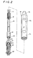
- a hand grip 16 is axially movably fitted on the bottom portion of the pole 15.
- the lift cords 11 have the other ends pulled out of the bottom of the grip 16 and then terminated by a common bead 25.
- the grip 16 has a through bore 17 composed of upper, middle and lower portions 17a, 17b and 17c.
- the upper portion 17a has an inner diameter slightly larger than the outer diameter of the pole 15.
- the middle portion 17b is diametrally larger than the upper portion 17a to receive both a bushing 19 fitted on the bottom of the pole 15 and an auxiliary compression spring 18 loosely coiled on the pole 15.
- the auxiliary spring 18 is interposed between the upper annular end of the middle portion 17b and the upper end of the bushing 19.
- the lower portion 17c is diametrally larger than the middle portion 17b to receive a plug 21.
- the plug 21 is axially movably mounted within the lower portion 17c and prevented from slipping out of the grip 16 by a snap ring 22, which is fixedly disposed at the bottom of the lower portion 17c.
- a lock compression spring 23 is interposed between the plug 21 and the snap ring 22 to upwardly bias the plug 21.
- a plug hole 20 is fitted in the bottom of the bushing 19.
- the plug 21 is formed at its top center with a conical head 21a to be inserted into the plug hole 20.
- the plug 21 is also formed with a plurality of cord holes 21b surrounding the head.
- the lift cords 11 pass through the pole 15, through the plug hole 20, through the cord holes 21b, through the lock spring 23, and through the snap ring 22 and then extend outwardly from the bottom of the grip 16.
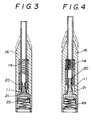
- the plug 21 When the blind or the bottom rail 13 rests, the plug 21 is inserted into the plug hole 20 under the action of the both compression springs 18 and 23. so that the lift cords 11 are fixedly clamped between the plug 21 and the plug hole 20.
- the lock spring 23 loosens though the plug 21 remains unmoved.
- the lift cords 11 are allowed to gradually slip between the plug 21 and the plug hole 20, so that the blind lowers slowly under its own weight but is prevented from falling rapidly due to the frictional resistance between the plug and the plug hole
- the blind falls at safety speeds upon operation of the hand grip 16 by a single hand even if it has been raised at the uppermost position.
- the grip 16 is further drawn from the halfway position shown by two-dot chain lines to the lowest position shown by solid lines.
- the auxiliary spring 18 is fully compressed.
- the plug 21 lowers together with the lock spring 23 loosened and slips out of the plug hole 20.
- the lift cords 11 are free from the locking between the plug 21 and the plug hole 20, so that the blind falls down to the lowermost position.
- the Venetian blind has two lift cords 11 each having one end extended downward from the head box 10, through slats 12, and to the bottom rail 13.
- the slats 12 are supported by the lift cords 11 when unfolded but by the ladder cords 29 when folded.
- the blind falls under its own weight corresponding to the weight of the slats 12 folded and the bottom rail 13.
- the blind weight is minimum or similar to the weight of only the bottom rail 13 when the blind is at the lowermost position, and maximum or similar to the weight of the all the slats 12 and the bottom rail 13 when the blind is at the uppermost position.
- the other end of the lift cord 11 extends to the pole 15 from the head box 10 through the hollow joint 14.
- a grip 16 is axially movably fitted on the bottom portion of the pole 15.
- the other ends of the lift cords 11 are pulled outwardly from the pole 15 and then terminate at a bead 25.
- the hollow pole 15 is provided at the bottom end thereof with a bushing 19 to prevent the hand grip 16 from slipping down out of the pole 15.
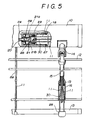
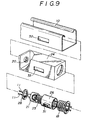
- a housing 24 is mounted within the head box 10.
- the housing 24 has the same longitudinal direction with the head box 10.
- a tubular holder 26 is longitudinally movably mounted within the housing 24.
- a plug 21 is axially movably mounted within the holder 26.
- the holder 26 is biassed toward one longitudinal side of the housing 24 under the action of an auxiliary compression spring 18, which is interposed between the holder 26 and a snap ring 27 at the other longitudinal side of the housing 24.
- the housing 24 is provided at the longitudinal side with a plug hole 20.
- the plug 21 is formed at its center with a conical head 21a for fitting engagement with the plug hole 20.
- the plug 21 is formed about the head 21a with a plurality of cord holes 21b or cord grooves to guide the lift cords 11 across the plug 21.
- a lock spring 23 is interposed between the plug 21 and the holder 26.
- the head 21a is inserted into the plug hole 20 under the action of both the compression springs 18 and 23.
- a snap ring 28 is fitted in the one longitudinal side of the holder 26.
- a pull cord 30 has an end attached to the other longitudinal side of the holder 26.
- the other end of the pull cord 30 extends together with the lift cords 11 from the head box 10, through the hollow universal joint 14, and through the pole 15 and to the bottom of the grip 16.
- the cord 30 is arranged to pull the holder 21 toward the other longitudinal side of the housing 24 against the auxiliary spring 18, when the grip 16 is drawn downwardly.
- Two lift cords 11 enter the holder 26 through the plug hole 20 at the one longitudinal of the housing 24, and cross the plug 21 through the cord holes 21b. Thereafter, the cords 11 leave the housing 24 through the snap ring 27 at the other longitudinal side of the housing 24.
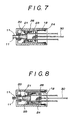
- the cord 30 When the grip is firstly pulled down, the cord 30 is drawn to compress the auxiliary spring 18 by half and move the holder 26 toward the other longitudinal side of the housing 24 to a certain extent that the lock spring 23 loosens while the plug 21 remains unmoved as seen in FIG. 7. Then, the lift cords 11 are allowed to gradually slip between the plug 21 and the plug hole 20, so that the blind lowers slowly under its own weight due to the frictional resistance between the plug and the plug hole
- the cord 30 When the grip is lastly pulled down, the cord 30 is drawn to compress the auxiliary spring 18 in full and move the holder 26 to the other longitudinal side of the housing 24 to the full extent that the snap ring 28 causes the plug 21 to move away from the plug hole 20 and release the lift cords 11 from the locking between the plug 21 and the plug hole 20, as seen in FIG. 8.
- the bottom rail lowers at the lowermost position.
- the grip 16 has no other role than a bead terminating the cord 30. It is required to be axially movably fitted on the pole 15 and have such an outer diameter that is somewhat larger than the pole 15. The grip can be eliminated if the cord is so pulled down outwardly from the lower end of the pole and operable apart from the lift cords 11. At any rate, the blind falls at safety speeds upon operation of the hand grip or the pull cord by a single hand even if it has been raised at the uppermost position.
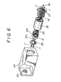
- a cord is substituted by a knob 31 which is fixed to the holder 26.
- the embodiment allows the blind to have no cord passing through the pole, nor grip to be fitted on the bottom portion of the pole.
- the knob 31 projects outwardly from a window 32 formed in the front of the head box 10 through a window 33 formed in the front of the housing 24.
- the plug 21 is inserted into the plug hole 20 under the action of both the compression springs 18 and 23 to lock the lift cords 11 between the plug 21 and the plug hole 20 when the blind rests.
- the lock spring 23 loosens while the plug 21 remains unmoved. Then, the lift cords 11 are allowed to gradually slip between the plug 21 and the plug hole 20 so that the blind falls slowly under its own weight. Thus, the blind falls at safety speeds upon operation of the knob 31 by a single hand even if it has been raised at the uppermost position.
Landscapes
- Engineering & Computer Science (AREA)
- Structural Engineering (AREA)
- Architecture (AREA)
- Civil Engineering (AREA)
- Blinds (AREA)
Claims (10)
- Seilklemmanordnung in Kombination mit einer Rafflamellenjalousie der Art, welche einen Kopfkasten (10), eine von dem Kopfkasten herabhängende hohle Stange (15) und einen Handgriff (16) aufweist, der axial bewegbar an den Bodenabschnitt der hohlen Stange angepaßt ist, wobei die Anordnung ein Stopfenloch (20), das koaxial an dem Boden der hohlen Stange (15) fixiert ist, einen Stopfen (21) innerhalb des Handgriffes zum Paßeingriff mit dem Stopfenloch von der Unterseite, eine Hilfskompressionsfeder (18), welche zwischen dem Griff und der Stange angeordnet ist, um den Griff aufwärts vorzuspannen, und Hebeseile (11) umfaßt, welche in den Griff durch das Stopfenloch eintreten und den Griff durch dessen Boden verlassen, dadurch gekennzeichnet, daß der Stopfen (21) axial bewegbar innerhalb des Handgriffes (16) angeordnet ist und von einer Verriegelungskompressionsfeder (23) aufwärts vorgespannt ist, welche zwischen dem Stopfen (21) und dem Handgriff (16) angeordnet ist, wobei die Hebeseile zwischen dem Stopfen und dem Stopfenloch durch die Verriegelungskompressionsfeder stramm festgeklemmt sind, wenn der Handgriff nicht gezogen ist, wobei die Hebeseile graduell bewegbar zwischen dem Stopfen und dem Stopfenloch geklemmt sind, wenn der Handgriff zunächst in eine Halbposition gezogen wird, in welcher die Verriegelungskompressionsfeder gelockert wird, während der Stopfen unbewegbar in dem Stopfenloch verbleibt, und wobei die Hebeseile aus der Klemmung zwischen dem Stopfen und dem Stopfenloch befreit werden, wenn der Handgriff weiter aus seiner Halbposition gezogen wird, um den Stopfen aus dem Stopfenloch fort zu bewegen.
- Anordnung nach Anspruch 1, wobei der Stopfen (21) mittig mit einem konischen Kopf (21a), der in das Stopfenloch (20) einzusetzen ist und am Umfang mit einer Vielzahl von Seillöchern ausgebildet ist, um die Hebeseile (11) im Bereich des Stopfens (21) zu führen.
- Anordnung nach Anspruch 1, wobei der Handgriff (16) eine Durchgangsbohrung (17) aufweist, die aus oberen, mittleren und unteren Teilen (17a, 17b und 17c) zusammengesetzt ist, wobei der obere Teil (17a) bewegbar an die hohle Stange (15) angepaßt ist, der mittlere Teil (17b) im Durchmesser größer als der obere Teil ist, um die Hilfskompressionsfeder (18) aufzunehmen, die zwischen dem oberen ringförmigen Ende des mittleren Teiles und einer Buchse (19) angeordnet ist, welche an dem Boden der hohlen Stange (15) befestigt ist, der untere Teil (17c) im Durchmesser größer ist als der mittlere Teil, um den Stopfen (21) und die Verriegelungskompressionsfeder (23) aufzunehmen, die zwischen dem Stopfen (21) und einem Sprengring (22) angeordnet ist, welcher in dem Boden des unteren Teiles befestigt ist.
- Seilklemmanordnung in Kombination mit einer Rafflamellenjalousie, umfassend einen Kopfkasten (10), ein Gehäuse (24), das in dem Kopfkasten angeordnet ist, ein Stopfenloch (20), das in einer Längsseite des Gehäuses vorgesehen ist, einen Stopfen (21), der in dem Gehäuse zwecks Passeingriffes mit dem Stopfenloch angeordnet ist und zu einer Längsseite des Gehäuses durch eine Verriegelungskompressionsfeder (23) vorgespannt ist, Hebeseile (11), die in das Gehäuse von dem Stopfenloch eintreten und das Gehäuse von dessen anderer Longitudinalseite verlassen und eine Freigabeeinrichtung (30, 31), um die Hebeseile aus der Klemmung zwischen dem Stopfen und dem Stopfenloch zu lösen, dadurch gekennzeichnet, daß der Stopfen (21) longitudinal bewegbar innerhalb eines Halters (26) angeordnet ist, welcher longitudinal bewegbar innerhalb des Gehäuses (24) vorgesehen ist, daß die Verriegelungskompressionsfeder (23) zwischen dem Stopfen (21) und dem Halter (26) angeordnet ist, daß der Halter (26) zu der einen longitudinalen Seite des Gehäuses (24) durch eine Hilfskompressionsfeder (18) vorgespannt ist, die zwischen dem Gehäuse (24) und dem Halter (26) angeordnet ist, und daß die Freigabeeinrichtung betätigbar ist, um den Halter (26) zu der anderen Longitudinalseite des Gehäuses (24) zu bewegen, wobei die Hebeseile zwischen dem Stopfen und dem Stopfenloch durch die Verriegelungskompressionsfeder festgeklemmt sind, wenn die Freigabeeinrichtung nicht betätigt wird, wobei die Hebeseile graduell bewegbar zwischen dem Stopfen und dem Stopfenloch verriegelt bzw. geklemmt sind, wenn die Freigabeeinrichtung zunächst betätigt wird, um den Halter zu einem gewissen Ausmaß zu bewegen, so daß sich die Verriegelungskompressionsfeder lockert, während der Stopfen unbewegt in dem Stopfenloch verbleibt und wobei die Hebeseile aus der Klemmung zwischen dem Stopfen und dem Stopfenloch freigegeben werden, wenn die Freigabeeinrichtung weiter betätigt wird, um den Halter zu vollem Ausmaß zu bewegen, so daß sich der Stopfen von dem Stopfenloch fort bewegt.
- Anordnung nach Anspruch 4, wobei der Stopfen (21) mittig mit einem konischen Kopf (21a), der in das Stopfenloch (20) einzusetzen ist und umfangsmäßig mit einer Vielzahl von Seillöchern (21b) ausgebildet ist, um die Hebeseile (11) im Bereich des Stopfens (21) zu führen.
- Anordnung nach Anspruch 4, wobei die Freigabeeinrichtung einen Knopf (31) umfaßt, der an dem Halter (26) befestigt ist, wobei der Knopf nach vorn durch ein Fenster (32) in dem Kopfkasten (10) und durch ein Fenster (33) in dem Gehäuse (24) ragt.
- Anordnung nach Anspruch 4, wobei die Freigabeeinrichtung ein Zugseil (30) umfaßt, dessen eines Ende an dem Halter (26) fixiert ist, und dessen anderes Ende sich zwecks Betätigung von dem Kopfgehäuse (10) erstreckt.
- Anordnung nach Anspruch 7, wobei die Jalousie eine hohle Stange (15) aufweist, die von dem Kopfkasten (10) herabhängt, wobei das andere Ende des Zugseils (30) durch die Stange läuft und aus deren Boden herausgezogen wird.
- Anordnung nach Anspruch 7, wobei die Jalousie eine hohle Stange (15), die von dem Kopfkasten (10) herabhängt, und einen Handgriff (16) aufweist, der axial bewegbar an den Bodenabschnitt der Stange (15) angepaßt ist, wobei das andere Ende des Zugseils (30) durch die Stange (15) führt und an dem Griff (16) befestigt ist.
- Seilklemmanordnung mit einem Gehäuse (15, 24), einem Stopfenloch (20), das in einer Längsseite des Gehäuses vorgesehen ist, einem Halter (16, 26), der longitudinal bewegbar mit dem Gehäuse gekoppelt ist, einem Stopfen (21), der koaxial mit dem Stopfenloch und longitudinal bewegbar innerhalb des Halters angeordnet ist, einer Verriegelungskompressionsfeder (23), die zwischen dem Stopfen und dem Halter angeordnet ist, um den Stopfen in das Stopfenloch vorzuspannen, einer Hilfskompressionsfeder (18), die zwischen dem Gehäuse und dem Halter angeordnet ist, um den Halter in die Richtung vorzuspannen, in welche sich die Verriegelungskompressionsfeder lockert, und Seilen (11), die zwischen dem Stopfenloch und dem Stopfen durchlaufen, dadurch gekennzeichnet, daß die Seile fest zwischen dem Stopfen und dem Stopfenloch durch die Verriegelungskompressionsfeder stramm festgeklemmt sind, wenn der Halter in einer anfänglichen Position ist, die Seile graduell bewegbar zwischen dem Stopfen und dem Stopfenloch geklemmt sind, wenn der Halter zunächst aus der anfänglichen Position in eine Halbposition bewegt wird, in welcher sich die Verriegelungskompressionsfeder lockert, während der Stopfen unbewegbar in dem Stopfenloch verbleibt, und daß die Seile aus der Klemmung zwischen dem Stopfen und dem Stopfenloch gelöst werden, wenn der Halter weiter aus der Halbposition bewegt wird, um den Stopfen von dem Stopfenloch fort zu bewegen.
Applications Claiming Priority (2)
| Application Number | Priority Date | Filing Date | Title |
|---|---|---|---|
| JP01329194A JP3266168B2 (ja) | 1994-02-07 | 1994-02-07 | ベネシャンブラインドの昇降操作装置 |
| JP13291/94 | 1994-02-07 |
Publications (2)
| Publication Number | Publication Date |
|---|---|
| EP0666404A1 EP0666404A1 (de) | 1995-08-09 |
| EP0666404B1 true EP0666404B1 (de) | 1998-01-07 |
Family
ID=11829100
Family Applications (1)
| Application Number | Title | Priority Date | Filing Date |
|---|---|---|---|
| EP19940116012 Expired - Lifetime EP0666404B1 (de) | 1994-02-07 | 1994-10-11 | Seilklemme für Rafflamellenstore |
Country Status (3)
| Country | Link |
|---|---|
| EP (1) | EP0666404B1 (de) |
| JP (1) | JP3266168B2 (de) |
| DE (1) | DE69407746T2 (de) |
Cited By (1)
| Publication number | Priority date | Publication date | Assignee | Title |
|---|---|---|---|---|
| AU2012216468B2 (en) * | 2012-05-18 | 2014-11-13 | Guangzhou Garden Rubber & Plastic Co., Ltd., | Venetian blind and operating device thereof |
Families Citing this family (6)
| Publication number | Priority date | Publication date | Assignee | Title |
|---|---|---|---|---|
| US6483195B1 (en) | 1999-03-16 | 2002-11-19 | Sumitomo Bakelite Company Limited | Transfer bump street, semiconductor flip chip and method of producing same |
| JP4252031B2 (ja) * | 2004-12-24 | 2009-04-08 | 株式会社ニチベイ | ブラインド用ストッパ装置 |
| US9194177B2 (en) | 2010-12-30 | 2015-11-24 | Hunter Douglas Inc. | Operating cord system for retractable coverings for architectural openings |
| JP6864616B2 (ja) | 2015-06-05 | 2021-04-28 | 立川ブラインド工業株式会社 | 制動装置及びこれを備えた遮蔽装置 |
| JP6438918B2 (ja) * | 2016-07-28 | 2018-12-19 | 株式会社Tok | 制動装置、及び、それを用いた日射遮蔽装置 |
| JP7026352B2 (ja) * | 2018-05-31 | 2022-02-28 | 立川ブラインド工業株式会社 | コード制動装置およびこのコード制動装置を備えた遮蔽装置 |
Family Cites Families (2)
| Publication number | Priority date | Publication date | Assignee | Title |
|---|---|---|---|---|
| NL155911B (nl) * | 1968-09-19 | 1978-02-15 | Silverflex Int Nv | Bedieningsinrichting voor een jaloezie. |
| DE2953496C2 (de) * | 1979-04-27 | 1983-10-20 | Toso K.K., Tokyo | Betätigungseinrichtung für eine Jalousie |
-
1994
- 1994-02-07 JP JP01329194A patent/JP3266168B2/ja not_active Expired - Fee Related
- 1994-10-11 DE DE1994607746 patent/DE69407746T2/de not_active Expired - Fee Related
- 1994-10-11 EP EP19940116012 patent/EP0666404B1/de not_active Expired - Lifetime
Cited By (2)
| Publication number | Priority date | Publication date | Assignee | Title |
|---|---|---|---|---|
| AU2012216468B2 (en) * | 2012-05-18 | 2014-11-13 | Guangzhou Garden Rubber & Plastic Co., Ltd., | Venetian blind and operating device thereof |
| US8931538B2 (en) | 2012-05-18 | 2015-01-13 | Guangzhou Garden Rubber & Plastic Co., Ltd. | Venetian blind and operating device thereof |
Also Published As
| Publication number | Publication date |
|---|---|
| JPH07217336A (ja) | 1995-08-15 |
| EP0666404A1 (de) | 1995-08-09 |
| DE69407746T2 (de) | 1998-06-18 |
| JP3266168B2 (ja) | 2002-03-18 |
| DE69407746D1 (de) | 1998-02-12 |
Similar Documents
| Publication | Publication Date | Title |
|---|---|---|
| US5501262A (en) | Cord locking assembly for use with venetian blind | |
| US5485875A (en) | Window shade with break-away attachment of lift cords to bottom rail | |
| US6029734A (en) | Venetian blind provided with slat-lifting mechanism having a concealed pull cord | |
| US5850863A (en) | Operating device for a venetian blind to control raising and lowering of the slats and to adjust tilting angle of the slats | |
| US7096917B2 (en) | One way brake for a cordless blind | |
| US5904198A (en) | Operating device for a venetian blind to control raising and lowering of the slats and to adjust tilting angle of the slats | |
| US6684930B2 (en) | Brake for a cordless blind | |
| CA2390484C (en) | Venetian blind that keeps lift cords concealed | |
| JP5313473B2 (ja) | ベネチアンブラインドのデュアルファンクション機構 | |
| CA2222487C (en) | Operating device for a venetian blind to control raising and lowering of the slats and to adjust tilting angle of the slats | |
| CA2377635A1 (en) | Cordless blind | |
| US20030201076A1 (en) | Venetian blind with concealed lift cords | |
| EP0666404B1 (de) | Seilklemme für Rafflamellenstore | |
| US7198089B2 (en) | Pull cord operation mechanism for blinds | |
| US6263946B1 (en) | Window covering cord safety assembly | |
| EP3228805A1 (de) | Regelmechanismus für eine jalousie | |
| US20030192654A1 (en) | Lift coard concealable venetian blind | |
| JP3284520B2 (ja) | ベネシャンブラインドの昇降操作装置 | |
| JPH08199945A (ja) | ベネシャンブラインドの昇降操作装置 | |
| JPH08210059A (ja) | ベネシャンブラインドの昇降操作装置 | |
| EP1574660A2 (de) | Architektonische Abdeckung mit einer Schnur, einer Schnurbetätigung und einem Schnurschloss | |
| JPH08254085A (ja) | ベネシャンブラインドの昇降操作装置 | |
| JPH08177348A (ja) | ベネシャンブラインドの昇降操作装置 | |
| JPH08158762A (ja) | ベネシャンブラインドの昇降操作装置 | |
| JP2551170Y2 (ja) | ブラインド操作装置 |
Legal Events
| Date | Code | Title | Description |
|---|---|---|---|
| PUAI | Public reference made under article 153(3) epc to a published international application that has entered the european phase |
Free format text: ORIGINAL CODE: 0009012 |
|
| AK | Designated contracting states |
Kind code of ref document: A1 Designated state(s): CH DE FR GB IT LI |
|
| 17P | Request for examination filed |
Effective date: 19950706 |
|
| 17Q | First examination report despatched |
Effective date: 19961029 |
|
| GRAG | Despatch of communication of intention to grant |
Free format text: ORIGINAL CODE: EPIDOS AGRA |
|
| GRAG | Despatch of communication of intention to grant |
Free format text: ORIGINAL CODE: EPIDOS AGRA |
|
| GRAH | Despatch of communication of intention to grant a patent |
Free format text: ORIGINAL CODE: EPIDOS IGRA |
|
| GRAH | Despatch of communication of intention to grant a patent |
Free format text: ORIGINAL CODE: EPIDOS IGRA |
|
| GRAA | (expected) grant |
Free format text: ORIGINAL CODE: 0009210 |
|
| AK | Designated contracting states |
Kind code of ref document: B1 Designated state(s): CH DE FR GB IT LI |
|
| ITF | It: translation for a ep patent filed | ||
| REG | Reference to a national code |
Ref country code: CH Ref legal event code: NV Representative=s name: HEPP, WENGER & RYFFEL AG Ref country code: CH Ref legal event code: EP |
|
| REF | Corresponds to: |
Ref document number: 69407746 Country of ref document: DE Date of ref document: 19980212 |
|
| ET | Fr: translation filed | ||
| PLBE | No opposition filed within time limit |
Free format text: ORIGINAL CODE: 0009261 |
|
| STAA | Information on the status of an ep patent application or granted ep patent |
Free format text: STATUS: NO OPPOSITION FILED WITHIN TIME LIMIT |
|
| 26N | No opposition filed | ||
| PGFP | Annual fee paid to national office [announced via postgrant information from national office to epo] |
Ref country code: FR Payment date: 20010822 Year of fee payment: 8 |
|
| PGFP | Annual fee paid to national office [announced via postgrant information from national office to epo] |
Ref country code: GB Payment date: 20010823 Year of fee payment: 8 |
|
| PGFP | Annual fee paid to national office [announced via postgrant information from national office to epo] |
Ref country code: CH Payment date: 20011023 Year of fee payment: 8 |
|
| PGFP | Annual fee paid to national office [announced via postgrant information from national office to epo] |
Ref country code: DE Payment date: 20011127 Year of fee payment: 8 |
|
| REG | Reference to a national code |
Ref country code: GB Ref legal event code: IF02 |
|
| PG25 | Lapsed in a contracting state [announced via postgrant information from national office to epo] |
Ref country code: GB Free format text: LAPSE BECAUSE OF NON-PAYMENT OF DUE FEES Effective date: 20021011 |
|
| PG25 | Lapsed in a contracting state [announced via postgrant information from national office to epo] |
Ref country code: LI Free format text: LAPSE BECAUSE OF NON-PAYMENT OF DUE FEES Effective date: 20021031 Ref country code: CH Free format text: LAPSE BECAUSE OF NON-PAYMENT OF DUE FEES Effective date: 20021031 |
|
| PG25 | Lapsed in a contracting state [announced via postgrant information from national office to epo] |
Ref country code: DE Free format text: LAPSE BECAUSE OF NON-PAYMENT OF DUE FEES Effective date: 20030501 |
|
| GBPC | Gb: european patent ceased through non-payment of renewal fee |
Effective date: 20021011 |
|
| REG | Reference to a national code |
Ref country code: CH Ref legal event code: PL |
|
| PG25 | Lapsed in a contracting state [announced via postgrant information from national office to epo] |
Ref country code: FR Free format text: LAPSE BECAUSE OF NON-PAYMENT OF DUE FEES Effective date: 20030630 |
|
| REG | Reference to a national code |
Ref country code: FR Ref legal event code: ST |
|
| PG25 | Lapsed in a contracting state [announced via postgrant information from national office to epo] |
Ref country code: IT Free format text: LAPSE BECAUSE OF NON-PAYMENT OF DUE FEES;WARNING: LAPSES OF ITALIAN PATENTS WITH EFFECTIVE DATE BEFORE 2007 MAY HAVE OCCURRED AT ANY TIME BEFORE 2007. THE CORRECT EFFECTIVE DATE MAY BE DIFFERENT FROM THE ONE RECORDED. Effective date: 20051011 |