EP0666237A1 - Procede de production d'eau - Google Patents
Procede de production d'eau Download PDFInfo
- Publication number
- EP0666237A1 EP0666237A1 EP93921117A EP93921117A EP0666237A1 EP 0666237 A1 EP0666237 A1 EP 0666237A1 EP 93921117 A EP93921117 A EP 93921117A EP 93921117 A EP93921117 A EP 93921117A EP 0666237 A1 EP0666237 A1 EP 0666237A1
- Authority
- EP
- European Patent Office
- Prior art keywords
- water
- hydrogen
- oxygen
- gas
- concentration
- Prior art date
- Legal status (The legal status is an assumption and is not a legal conclusion. Google has not performed a legal analysis and makes no representation as to the accuracy of the status listed.)
- Withdrawn
Links
Images


Classifications
-
- C—CHEMISTRY; METALLURGY
- C01—INORGANIC CHEMISTRY
- C01B—NON-METALLIC ELEMENTS; COMPOUNDS THEREOF; METALLOIDS OR COMPOUNDS THEREOF NOT COVERED BY SUBCLASS C01C
- C01B5/00—Water
Definitions
- the present invention relates to a water generating method.
- the present invention has as an object thereof to provide a water generating method which is capable of providing a large quantity of water-mixed gas having an accurate water concentration in a wide range from a low level, on the order of ppt and ppb, to a high level, on the order of percentage, and super-high cleanness, and which, furthermore, is quick to respond and simple to maintain.
- the water generating method of the present invention is characterized in comprising, in a method for generating water by reacting hydrogen and oxygen, a mixed gas preparation process in which hydrogen, oxygen, and an inert gas are mixed to produce a mixed gas, and a water generating process, in which the hydrogen and oxygen contained in the mixed gas are reacted within a reaction tube comprising a material having a catalytic action and which is heated, and water is generated.
- a catalytic material which lowers the reaction temperature is employed in the reaction tube which causes the hydrogen and oxygen to react, so that the reaction temperature is lowered, and as a result, water generation becomes possible at low temperatures. Accordingly, when a mixed gas of hydrogen, oxygen, and an inert gas is supplied to a heated reaction tube, the hydrogen and oxygen can be completely reacted at a temperature of 500°C or less within the reaction tube, so that in comparison with the conventional technology, gas containing water can be obtained at low temperatures.
- the reaction temperature need only be raised to a temperature at which hydrogen and oxygen will completely react or higher, so that accurate temperature control is unnecessary.
- Such passivation processing may be conducted, for example, by subjecting SUS316L, which has been subjected to electropolishing or electrolytic composite polishing, to heat treatment in an oxidizing or weakly oxidizing atmosphere having an impurity concentration on the level of a few ppb or less (as in, for example, Japanese Patent Application, No. Sho 63-5389, PCT/JP92/699, and Japanese Patent Application, No. Hei 4-164377).
- a point to which special attention should be paid is that, in addition to the fact that very little water is emitted from the surface of the passivated film, this surface itself has an action which is capable of turning hydrogen and oxygen into radicals. Accordingly, the use of a reaction tube having such a passivated film on the inner surface thereof is extremely effective from the point of view of generating water with high accuracy.
- the fact that it is not the base material itself, but rather the oxides, formed with the base material elements, formed on the surface thereof, which produce a catalytic action capable of turning the hydrogen and oxygen into radicals, is not easily understood and is surprising; in the present invention, the characteristic of the small amounts of water emitted from the surface, and the characteristic of the catalytic action, are skillfully taken advantage of.
- the water concentration which is generated is determined by the hydrogen or oxygen concentration, so that it is sufficient to confirm the flow rate of the hydrogen and oxygen gases, so that calibration can be carried out simply in a short period of time. Furthermore, the gas storage area is extremely small, so that the response speed is very high, and it is possible to supply water at freely selected concentrations.
- Figure 1 is a conceptual diagram of a standard water generating apparatus in accordance with Embodiment 1.
- Figure 2 shows the results of a measurement of the water concentration in a gas flowing from a standard water generating apparatus in accordance with Embodiment 1.
- Figure 3 shows the results of a measurement of the oxygen concentration in a gas flowing from a standard water generating apparatus in accordance with Embodiment 1.
- Figure 4 is a conceptual diagram of a standard water generating apparatus in accordance with Embodiment 2.
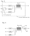
- Figure 5 is a conceptual diagram of a standard water generating apparatus in accordance with Embodiment 3.
- Figure 6 is a conceptual diagram of a standard water generating apparatus in accordance with Embodiment 4.
- Figure 7 is a conceptual diagram of a standard water generating apparatus in accordance with Embodiment 5.
- Figure 8 shows the results of a measurement of the water concentration in a gas flowing from a standard water generating apparatus in accordance with Embodiment 5.
- Figure 9 shows the results of a measurement of the hydrogen concentration in a gas flowing from a standard water generating apparatus in accordance with Embodiment 5.
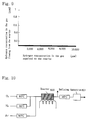
- Figure 10 is a conceptual diagram of a standard water generating apparatus in accordance with Embodiment 6.
- FIG 11 is a conceptual diagram of a standard water generating apparatus in accordance with Embodiment 7.
- Figure 12 is a conceptual diagram of a standard water generating apparatus in accordance with Embodiment 8.
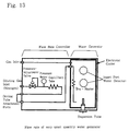
- Figure 13 is a conceptual diagram showing conventional technology.
- Figure 14 is a conceptual diagram showing a conventional example.
- Figure 15 is a conceptual diagram showing a conventional example.
- Figure 16 is a conceptual diagram showing a conventional example.
- the present embodiment involves the case in which, using a mixed gas of oxygen, hydrogen, and argon, a freely selected water concentration is generated; a schematic view of the apparatus is shown in Figure 1.
- the flow rate of the oxygen gas is controlled by mass flow controller (MFC) 101
- the flow rate of the hydrogen gas is controlled by mass flow controller 102
- the flow rate of the argon gas is controlled by mass flow controller 103
- the three types of gas are passed through a mixing tube 104 where they are mixed, and are introduced into reactor 105.
- reactor 105 the hydrogen and oxygen are reacted, and a mixed gas of hydrogen and argon containing a freely selected water component is generated.
- a SUS316L stainless steel tube (the inner surface of which is electro polished) having a diameter of 1/4" and length of 2 m was used as reactor 105, and using the catalytic action of the surface of the stainless steel tube, a reduction in the reaction temperature was achieved.
- mass flow controllers 102 and 103 the flow rates of the hydrogen gas and the argon gas were fixed at 50 cc/min and 450 cc/min, respectively, and only the flow rate of the oxygen gas was varied within a range of 0.1 - 10 cc/min using mass flow controller 101, the three mixed gases were introduced into the reactor, and the water concentration and oxygen concentration in the mixed gas of hydrogen and argon flowing out of the reactor were measured using optical dew point meter (water concentration meter) 106 and galvanic battery-type oxygen analyzer 107. High purity gases having an impurity concentration of 1 ppb or less were used as the hydrogen, oxygen, and inert gas which were employed. The temperature of reactor 105 was maintained at 300°C over the entire length thereof.
- FIGs 2 and 3 The results of this measurement are shown in Figures 2 and 3.
- the horizontal axis shows the oxygen concentration in the mixed gas of hydrogen, oxygen, and argon, while the vertical axis shows the water concentration in the gas flowing from reactor 105.
- the horizontal axis indicates the oxygen concentration in the gas supplied to reactor 105, while the vertical axis shows the oxygen concentration flowing from reactor 105. From the results shown in Figure 2, it can be seen that a water concentration was detected in the gas flowing from the reactor which was twice that of the oxygen concentration supplied to reactor 105. The concentration of water generated was within a range of 100 ppb - 2%.
- Figure 3 shows that no matter what the oxygen concentration which was supplied to reactor 105, no oxygen was detected in the gas flowing from reactor 105. That is to say, a complete reaction of the hydrogen and oxygen occurred within the reactor, and the water component which was generated depended on the oxygen concentration supplied to reactor 105.
- the temperature of reactor 105 was set to 300°C; however, even at a temperature of 100°C, results identical to those described above were obtained, so that it was determined that when stainless steel was used in reactor 105, a temperature range of 100°C - 500°C was appropriate for reactor 105.
- 100% facility piping superpure gases were used as the hydrogen, oxygen, and argon (inert gas) gases; however, 100% concentration cylinders or mixed gas cylinders may also be employed.
- the temperature of rector 105 was set to 300°C; however, the supplied gas flow rate, the reaction tube volume (reaction time), and the reaction temperature are closely related, so that there are cases in which a temperature of less than 300°C may be used.
- SUS316L was used in the present embodiment as the reactor material; however, any metal may be employed insofar as it has a catalytic action which lowers the temperature of reaction of hydrogen and oxygen.
- embodiments include Hastelloy, nickel, platinum, and the like.
- metal having a catalytic action need not be used for the entirety of the reaction tube; it is acceptable if such metal is used in only a portion of the reaction tube, for example in only those portions which are in contact with gas.
- a catalytic metal is placed in the reactor in order to reduce the reaction initiation temperature between hydrogen and oxygen gas; a reactor 200, in which platinum fibers, which are a catalytic material, are provided within the reactor of Embodiment 1, is used as the reactor.
- a schematic diagram of the apparatus is shown in Figure 4. Other points are identical with Embodiment 1. It was confirmed that hydrogen and oxygen reacted completely even when the reactor 200 was at a temperature of 200°C.
- a diluting apparatus is provided before the hydrogen gas supply mass flow controller of Embodiment 1, and the supply of low-concentration hydrogen gas is thus made possible; in this case, the water concentration which is generated can be reduced.
- the entirety of the water generating apparatus is installed in a constant temperature bath, and the amount of water emitted from the piping or inner walls of the reactor is held constant. A schematic diagram of this apparatus is shown in Figure 5.
- gas containing a freely selected generated water component can be supplied at a freely selected flow rate; a schematic view of the apparatus is shown in Figure 6.
- a mass flow controller 401 is provided at the downstream side of the reactor 400, and in order to maintain the pressure between mass flow controller 401 and reactor 400 at a constant level, a blowoff tube 402 for blowing off a portion of the gas flowing from the reactor is provided.
- the hydrogen concentration was set so as to be excessive, and the water concentration was determined by means of the oxygen concentration; however, in the state in which it is the oxygen concentration which is excessive (in the present embodiment, an oxygen concentration of 10%), the water concentration flowing out from reactor 500 is controlled by means of the hydrogen concentration which is supplied.
- the temperature of the reactor was set to 400°C.
- a schematic view of the apparatus is shown in Figure 7. The results of an evaluation thereof are shown in Figures 8 and 9. It can be seen from the results of Figure 8 that a water concentration which equal to that of the hydrogen concentration supplied to reactor 500 was detected in the gas flowing from reactor 500.
- the water generation concentration was within a range of 100 ppb - 1%. From the results shown in Figure 9, it can be seen that no hydrogen gas was detected in the gas flowing from reactor 500, independent of the hydrogen concentration which was supplied to reactor 500. In other words, a complete reaction of the hydrogen and the oxygen occurred in reactor 500, and a water component corresponding to the hydrogen concentration supplied to reactor 500 was generated.
- the present embodiment could be applied to an apparatus for the generation of mixed gas containing a freely selected concentration of super pure water.
- the hydrogen gas or oxygen gas remaining in the gas containing a generated water component is removed; in the case in which one or the other of hydrogen gas and oxygen gas is supplied in excess and reaction is conducted, as in Embodiments 1-5, there are cases in which the excessive hydrogen or oxygen component remains in the gas containing water which is produced.
- a refining apparatus 601 which is capable of selectively removing hydrogen or oxygen is installed on the downstream side of reactor 600, and the apparatus supplies gas containing a freely selected water concentration which does not contain hydrogen or oxygen; this apparatus is shown in Figure 10. The generation of gas containing neither hydrogen or oxygen, and containing only water was confirmed.
- a standard water generating apparatus having a function for stopping gas is used; considering, with respect to the apparatus in Embodiments 1-6, the occurrence of cases when the gas can not be stopped, the standard water generating apparatus is provided with a metal stop valve; a schematic view of the apparatus is shown in Figure 11. The generation of gas containing a freely selected water component was confirmed.
- the interior of the standard water generating apparatus was purged using inert gas, or at least a portion of the standard water generating apparatus was subjected to baking in order to accelerate the start-up of the standard water generating apparatus; the structure of the apparatus was identical to that of Figure 6, and is depicted again in Figure 12.
- the stable generation of gas containing 1 ppm of water was confirmed within 30 seconds from the start-up of the standard water generating apparatus.
Landscapes
- Chemical & Material Sciences (AREA)
- Organic Chemistry (AREA)
- Inorganic Chemistry (AREA)
- Feeding, Discharge, Calcimining, Fusing, And Gas-Generation Devices (AREA)
- Sampling And Sample Adjustment (AREA)
- Oxygen, Ozone, And Oxides In General (AREA)
Applications Claiming Priority (3)
| Application Number | Priority Date | Filing Date | Title |
|---|---|---|---|
| JP266383/92 | 1992-10-05 | ||
| JP26638392A JP3331636B2 (ja) | 1992-10-05 | 1992-10-05 | 水分発生方法 |
| PCT/JP1993/001430 WO1994007795A1 (fr) | 1992-10-05 | 1993-10-05 | Procede de production d'eau |
Publications (2)
| Publication Number | Publication Date |
|---|---|
| EP0666237A1 true EP0666237A1 (fr) | 1995-08-09 |
| EP0666237A4 EP0666237A4 (fr) | 1995-10-18 |
Family
ID=17430178
Family Applications (1)
| Application Number | Title | Priority Date | Filing Date |
|---|---|---|---|
| EP93921117A Withdrawn EP0666237A4 (fr) | 1992-10-05 | 1993-10-05 | Procede de production d'eau. |
Country Status (3)
| Country | Link |
|---|---|
| EP (1) | EP0666237A4 (fr) |
| JP (1) | JP3331636B2 (fr) |
| WO (1) | WO1994007795A1 (fr) |
Cited By (8)
| Publication number | Priority date | Publication date | Assignee | Title |
|---|---|---|---|---|
| EP0878443A1 (fr) * | 1996-01-29 | 1998-11-18 | FUJIKIN Inc. | Procede de production de vapeur d'eau, reacteur de production de vapeur d'eau, technique de regulation de la temperature de ce reacteur et procede de formation d'une couche catalytique recouverte de platine |
| EP0922667A1 (fr) * | 1997-06-17 | 1999-06-16 | FUJIKIN Inc. | Procede de production d'eau utile dans la fabrication de semiconducteurs |
| WO2001073834A1 (fr) * | 2000-03-24 | 2001-10-04 | Matrix Integrated Systems, Inc. | Procede d'attaque de polymeres de parois laterales et d'autres residus presents a la surface de dispositifs semiconducteurs |
| WO2001097308A2 (fr) * | 2000-06-13 | 2001-12-20 | Hydrogenics Corporation | Dispositif catalytique d'humidification et de chauffage pour le courant de combustible d'une pile a combustible |
| WO2001097310A2 (fr) * | 2000-06-13 | 2001-12-20 | Hydrogenics Corporation | Humidificateur et rechauffeur catalytique servant principalement a humidifier le flux de comburant d'une cellule electrochimique |
| US6524934B1 (en) | 1999-10-28 | 2003-02-25 | Lorimer D'arcy H. | Method of manufacture for generation of high purity water vapor |
| WO2003016213A1 (fr) * | 2001-08-13 | 2003-02-27 | Ultra Clean Technology Systems And Services Inc. | Appareil a reacteur catalytique et procede pour produire de la vapeur d'eau de grande purete |
| US6855642B2 (en) | 1997-03-05 | 2005-02-15 | Renesas Technology Corp. | Method for fabricating semiconductor integrated circuit device |
Families Citing this family (13)
| Publication number | Priority date | Publication date | Assignee | Title |
|---|---|---|---|---|
| JP3952087B2 (ja) * | 1996-06-20 | 2007-08-01 | 忠弘 大見 | 水分発生方法および水分発生装置 |
| ES2122906B1 (es) * | 1996-08-01 | 1999-07-01 | Portillo Cuerva Juan | Sistema para la produccion de agua potable con recuperacion de energia. |
| JP2007096335A (ja) * | 1997-03-05 | 2007-04-12 | Renesas Technology Corp | 半導体集積回路装置の製造方法 |
| JPH10335652A (ja) | 1997-05-30 | 1998-12-18 | Hitachi Ltd | 半導体集積回路装置の製造方法 |
| JP3644810B2 (ja) * | 1997-12-10 | 2005-05-11 | 株式会社フジキン | 少流量の水分供給方法 |
| JPH11330468A (ja) | 1998-05-20 | 1999-11-30 | Hitachi Ltd | 半導体集積回路装置の製造方法および半導体集積回路装置 |
| US6335295B1 (en) * | 1999-01-15 | 2002-01-01 | Lsi Logic Corporation | Flame-free wet oxidation |
| CN1290197C (zh) | 2001-03-12 | 2006-12-13 | 株式会社日立制作所 | 用于制造半导体集成电路器件的方法 |
| US7053459B2 (en) | 2001-03-12 | 2006-05-30 | Renesas Technology Corp. | Semiconductor integrated circuit device and process for producing the same |
| KR100684554B1 (ko) * | 2001-04-03 | 2007-02-20 | 서울대학교병원 | 질량수가 15인 n을 재사용하는 것을 특징으로 하는, 질량수가 15인 o로 표지된 물의 생산 장치 및 생산 방법 |
| GB2420851B (en) * | 2004-12-04 | 2009-05-06 | Siemens Ind Turbomachinery Ltd | A probe for use in determining the amount of a first gas component in a combustion gas |
| JP4620654B2 (ja) * | 2006-12-25 | 2011-01-26 | 株式会社日立製作所 | 半導体集積回路装置の製造方法 |
| CN113941295B (zh) * | 2021-11-12 | 2023-10-20 | 西北核技术研究所 | 一种氢气高效转化为水的方法及装置 |
Citations (4)
| Publication number | Priority date | Publication date | Assignee | Title |
|---|---|---|---|---|
| DE2736343A1 (de) * | 1977-08-12 | 1979-03-01 | Messer Griesheim Gmbh | Verfahren zur herstellung eines gases mit definiertem feuchtigkeitsgehalt |
| DE2831287A1 (de) * | 1978-07-17 | 1980-01-31 | Josef Hammer | Verfahren zur erzeugung einer definierten wasserdampfmenge geringer konzentration und vorrichtung zur durchfuehrung des verfahrens |
| US4302419A (en) * | 1980-02-13 | 1981-11-24 | Helix Technology Corporation | Catalytic recombiner system |
| EP0303144A1 (fr) * | 1987-08-14 | 1989-02-15 | Siemens Aktiengesellschaft | Dispositif pour la recombinaison de l'hydrogène et de l'oxygène |
Family Cites Families (2)
| Publication number | Priority date | Publication date | Assignee | Title |
|---|---|---|---|---|
| JPS6087857A (ja) * | 1983-10-20 | 1985-05-17 | Kansai Coke & Chem Co Ltd | 酸化触媒 |
| JPS61197404A (ja) * | 1985-02-26 | 1986-09-01 | Nippon Sanso Kk | 所定水分含有ガス発生装置 |
-
1992
- 1992-10-05 JP JP26638392A patent/JP3331636B2/ja not_active Expired - Fee Related
-
1993
- 1993-10-05 EP EP93921117A patent/EP0666237A4/fr not_active Withdrawn
- 1993-10-05 WO PCT/JP1993/001430 patent/WO1994007795A1/fr not_active Application Discontinuation
Patent Citations (4)
| Publication number | Priority date | Publication date | Assignee | Title |
|---|---|---|---|---|
| DE2736343A1 (de) * | 1977-08-12 | 1979-03-01 | Messer Griesheim Gmbh | Verfahren zur herstellung eines gases mit definiertem feuchtigkeitsgehalt |
| DE2831287A1 (de) * | 1978-07-17 | 1980-01-31 | Josef Hammer | Verfahren zur erzeugung einer definierten wasserdampfmenge geringer konzentration und vorrichtung zur durchfuehrung des verfahrens |
| US4302419A (en) * | 1980-02-13 | 1981-11-24 | Helix Technology Corporation | Catalytic recombiner system |
| EP0303144A1 (fr) * | 1987-08-14 | 1989-02-15 | Siemens Aktiengesellschaft | Dispositif pour la recombinaison de l'hydrogène et de l'oxygène |
Non-Patent Citations (1)
| Title |
|---|
| See also references of WO9407795A1 * |
Cited By (23)
| Publication number | Priority date | Publication date | Assignee | Title |
|---|---|---|---|---|
| EP0878443A4 (fr) * | 1996-01-29 | 2006-09-27 | Fujikin Kk | Procede de production de vapeur d'eau, reacteur de production de vapeur d'eau, technique de regulation de la temperature de ce reacteur et procede de formation d'une couche catalytique recouverte de platine |
| EP0878443A1 (fr) * | 1996-01-29 | 1998-11-18 | FUJIKIN Inc. | Procede de production de vapeur d'eau, reacteur de production de vapeur d'eau, technique de regulation de la temperature de ce reacteur et procede de formation d'une couche catalytique recouverte de platine |
| US6855642B2 (en) | 1997-03-05 | 2005-02-15 | Renesas Technology Corp. | Method for fabricating semiconductor integrated circuit device |
| US7799690B2 (en) | 1997-03-05 | 2010-09-21 | Renesas Electronics Corporation | Method for fabricating semiconductor integrated circuit device |
| US7250376B2 (en) | 1997-03-05 | 2007-07-31 | Renesas Technology Corp. | Method for fabricating semiconductor integrated circuit device |
| US7053007B2 (en) | 1997-03-05 | 2006-05-30 | Renesas Technology Corp. | Method for fabricating semiconductor integrated circuit device |
| US7008880B2 (en) | 1997-03-05 | 2006-03-07 | Renesas Technology Corp. | Method for fabricating semiconductor integrated circuit device |
| US6962880B2 (en) | 1997-03-05 | 2005-11-08 | Renesas Technology Corp. | Method for fabricating semiconductor integrated circuit device |
| US6962881B2 (en) | 1997-03-05 | 2005-11-08 | Renesas Technology Corp. | Method for fabricating semiconductor integrated circuit device |
| EP0922667A1 (fr) * | 1997-06-17 | 1999-06-16 | FUJIKIN Inc. | Procede de production d'eau utile dans la fabrication de semiconducteurs |
| EP0922667A4 (fr) * | 1997-06-17 | 2003-05-28 | Fujikin Kk | Procede de production d'eau utile dans la fabrication de semiconducteurs |
| US6524934B1 (en) | 1999-10-28 | 2003-02-25 | Lorimer D'arcy H. | Method of manufacture for generation of high purity water vapor |
| US6667244B1 (en) | 2000-03-24 | 2003-12-23 | Gerald M. Cox | Method for etching sidewall polymer and other residues from the surface of semiconductor devices |
| WO2001073834A1 (fr) * | 2000-03-24 | 2001-10-04 | Matrix Integrated Systems, Inc. | Procede d'attaque de polymeres de parois laterales et d'autres residus presents a la surface de dispositifs semiconducteurs |
| US6790546B2 (en) | 2000-06-13 | 2004-09-14 | Hydrogenics Corporation | Method of heating and humidifying at least one of a fuel stream and an oxidant stream for a fuel cell |
| US6746789B1 (en) | 2000-06-13 | 2004-06-08 | Hydrogenics Corporation | Catalytic humidifier and heater for the fuel stream of a fuel cell |
| US6706429B1 (en) | 2000-06-13 | 2004-03-16 | Hydrogenics Corporation | Catalytic humidifier and heater, primarily for humidification of the oxidant stream for a fuel cell |
| WO2001097308A3 (fr) * | 2000-06-13 | 2003-01-16 | Hydrogenics Corp | Dispositif catalytique d'humidification et de chauffage pour le courant de combustible d'une pile a combustible |
| WO2001097310A3 (fr) * | 2000-06-13 | 2003-01-09 | Hydrogenics Corp | Humidificateur et rechauffeur catalytique servant principalement a humidifier le flux de comburant d'une cellule electrochimique |
| WO2001097310A2 (fr) * | 2000-06-13 | 2001-12-20 | Hydrogenics Corporation | Humidificateur et rechauffeur catalytique servant principalement a humidifier le flux de comburant d'une cellule electrochimique |
| WO2001097308A2 (fr) * | 2000-06-13 | 2001-12-20 | Hydrogenics Corporation | Dispositif catalytique d'humidification et de chauffage pour le courant de combustible d'une pile a combustible |
| US7338727B2 (en) | 2000-06-13 | 2008-03-04 | Hydrogenics Corporation | Method of operating a fuel cell to provide a heated and humidified oxidant |
| WO2003016213A1 (fr) * | 2001-08-13 | 2003-02-27 | Ultra Clean Technology Systems And Services Inc. | Appareil a reacteur catalytique et procede pour produire de la vapeur d'eau de grande purete |
Also Published As
| Publication number | Publication date |
|---|---|
| EP0666237A4 (fr) | 1995-10-18 |
| JPH06115903A (ja) | 1994-04-26 |
| WO1994007795A1 (fr) | 1994-04-14 |
| JP3331636B2 (ja) | 2002-10-07 |
Similar Documents
| Publication | Publication Date | Title |
|---|---|---|
| EP0666237A1 (fr) | Procede de production d'eau | |
| US5149659A (en) | Method and apparatus for analyzing fluorine containing gases | |
| WO1994011901A1 (fr) | Appareil et procede pour former des films d'oxyde a basse temperature | |
| US5820823A (en) | Method and apparatus for the measurement of dissolved carbon | |
| US6772781B2 (en) | Apparatus and method for mixing gases | |
| US6818105B2 (en) | Apparatus for generating fluorine gas | |
| US5425803A (en) | Device for removing dissolved gas from a liquid | |
| KR0182281B1 (ko) | 고 정밀도의 전자 부품의 제작시스템 | |
| US5661225A (en) | Dynamic dilution system | |
| US4517220A (en) | Deposition and diffusion source control means and method | |
| EP0646400B1 (fr) | Appareil reducteur d'oxygene dissous | |
| GB1597192A (en) | High-pressure high-temperature gaseous chemical apparatus and method | |
| KR100225742B1 (ko) | 습식산화시스템에 대한 부식제어 | |
| US5378439A (en) | Process for removing gaseous hydrides from a solid support comprising metallic oxides | |
| JPH0662322B2 (ja) | ガラス―金属接合の製造に必要な雰囲気の製造方法及びそのための装置 | |
| US5702673A (en) | Ozone generating apparatus | |
| JPH0221875B2 (fr) | ||
| RU2407732C2 (ru) | Способ безопасного проведения газофазного частичного окисления | |
| EP0442250B1 (fr) | Méthode de contrÔle à l'aide du potentiel redox | |
| US6330819B1 (en) | Method and apparatus for calibrating a dissolved oxygen analyzer | |
| JP7141395B2 (ja) | ガス供給システムにおける過酸化水素の分解を抑制する方法、システム、および装置 | |
| US6171511B1 (en) | Thermal etching process of a ceramic under oxidizing conditions | |
| JP3952087B2 (ja) | 水分発生方法および水分発生装置 | |
| US5794114A (en) | Ozonizer | |
| US20240025785A1 (en) | Production device for ph/redox potential-adjusted water |
Legal Events
| Date | Code | Title | Description |
|---|---|---|---|
| PUAI | Public reference made under article 153(3) epc to a published international application that has entered the european phase |
Free format text: ORIGINAL CODE: 0009012 |
|
| 17P | Request for examination filed |
Effective date: 19950427 |
|
| AK | Designated contracting states |
Kind code of ref document: A1 Designated state(s): CH DE FR GB IT LI NL |
|
| A4 | Supplementary search report drawn up and despatched | ||
| AK | Designated contracting states |
Kind code of ref document: A4 Designated state(s): CH DE FR GB IT LI NL |
|
| 17Q | First examination report despatched |
Effective date: 19960130 |
|
| STAA | Information on the status of an ep patent application or granted ep patent |
Free format text: STATUS: THE APPLICATION HAS BEEN WITHDRAWN |
|
| 18W | Application withdrawn |
Withdrawal date: 19960814 |