EP0666205A1 - Diebstahlsicherung für Lenksäule, insbesondere von Kraftfahrzeugen - Google Patents
Diebstahlsicherung für Lenksäule, insbesondere von Kraftfahrzeugen Download PDFInfo
- Publication number
- EP0666205A1 EP0666205A1 EP95400210A EP95400210A EP0666205A1 EP 0666205 A1 EP0666205 A1 EP 0666205A1 EP 95400210 A EP95400210 A EP 95400210A EP 95400210 A EP95400210 A EP 95400210A EP 0666205 A1 EP0666205 A1 EP 0666205A1
- Authority
- EP
- European Patent Office
- Prior art keywords
- shaft
- sleeve
- complementary
- coupling
- locking
- Prior art date
- Legal status (The legal status is an assumption and is not a legal conclusion. Google has not performed a legal analysis and makes no representation as to the accuracy of the status listed.)
- Withdrawn
Links
Images


Classifications
-
- B—PERFORMING OPERATIONS; TRANSPORTING
- B60—VEHICLES IN GENERAL
- B60R—VEHICLES, VEHICLE FITTINGS, OR VEHICLE PARTS, NOT OTHERWISE PROVIDED FOR
- B60R25/00—Fittings or systems for preventing or indicating unauthorised use or theft of vehicles
- B60R25/01—Fittings or systems for preventing or indicating unauthorised use or theft of vehicles operating on vehicle systems or fittings, e.g. on doors, seats or windscreens
- B60R25/02—Fittings or systems for preventing or indicating unauthorised use or theft of vehicles operating on vehicle systems or fittings, e.g. on doors, seats or windscreens operating on the steering mechanism
- B60R25/021—Fittings or systems for preventing or indicating unauthorised use or theft of vehicles operating on vehicle systems or fittings, e.g. on doors, seats or windscreens operating on the steering mechanism restraining movement of the steering column or steering wheel hub, e.g. restraining means controlled by ignition switch
- B60R25/0215—Fittings or systems for preventing or indicating unauthorised use or theft of vehicles operating on vehicle systems or fittings, e.g. on doors, seats or windscreens operating on the steering mechanism restraining movement of the steering column or steering wheel hub, e.g. restraining means controlled by ignition switch using electric means, e.g. electric motors or solenoids
- B60R25/02156—Fittings or systems for preventing or indicating unauthorised use or theft of vehicles operating on vehicle systems or fittings, e.g. on doors, seats or windscreens operating on the steering mechanism restraining movement of the steering column or steering wheel hub, e.g. restraining means controlled by ignition switch using electric means, e.g. electric motors or solenoids comprising a locking member axially moved along the steering column
Definitions
- the present invention relates to an anti-theft device for a steering column assembly, in particular for a motor vehicle.
- the invention relates to anti-theft devices for steering column assemblies, which comprise a steering shaft rotatably mounted in a column body, and in which means are provided for blocking the rotation of the shaft relative to to the body, movable by a locking mechanism between an active locking position and a retracted position for releasing the shaft relative to the body.
- these devices include a locking mechanism fixed on the column body and controlled for example by a locking key actuated by a user, to obtain the displacement of a locking bolt between a retracted position and an active position, wherein this bolt engages through a lumen of the body and cooperates with means for blocking the rotation of the shaft relative to this body.
- These means for blocking the shaft may for example be constituted by slots or grooves formed therein or in a ring carried by this shaft and connected to it, for example by means of friction means, allowing the shaft to rotate relative to the ring when a very high torque is applied to it in order to avoid any degradation of the column assembly.
- this device has a certain number of drawbacks in terms of the engagement of the coupling means of the sleeve in the corresponding complementary means of the shaft.
- the object of the invention is therefore to solve these problems by proposing an anti-theft device which is simple and reliable.
- the subject of the invention is an anti-theft device for a steering column assembly, in particular for a motor vehicle, of the type comprising a steering shaft rotatably mounted in a column body and means for blocking the rotation of the shaft by relative to the body, displaceable by a locking mechanism between an active locking position and a retracted position for releasing the shaft relative to the body, the locking means comprising a sleeve interposed between the shaft and the body, comprising first and second coupling means adapted to cooperate with first and second means complementary to the shaft and the body respectively, for locking the shaft in rotation relative to the body and allowing axial movement of the sleeve by the locking mechanism , between the active blocking position and the retracted release position, in which the first and / or second coupling means are disengaged s corresponding complementary means, characterized in that the coupling means and the corresponding complementary means comprise tapered corresponding ends facilitating their engagement and in that the sleeve has a determined angular displacement stroke between the body and the shaft
- a steering column assembly in particular for a motor vehicle, generally comprises a steering shaft designated by the reference 1 rotatably mounted in a steering column body 2, for example by through guide bearings 3.
- An anti-theft device designated by the general reference 4 is also provided for locking the shaft in rotation in the body.
- this device comprises blocking means displaceable by a locking mechanism between an active blocking position and a retracted position for releasing the shaft relative to the body.
- the locking mechanism can have any suitable known structure, it will not be described in more detail below.
- this mechanism comprises for example a finger 5 for axial displacement of the locking means which are designated by the reference 6 in these figures.
- the locking means 6 comprise a sleeve interposed between the shaft 1 and the column body 2 and comprising for example on its internal and external surfaces first and second coupling means adapted to cooperate with first and second complementary means of the tree and the body respectively.
- the first and second coupling means of this sleeve are designated by the references 6a and 6b respectively.
- the first complementary means of the shaft are designated by the reference la, while the second complementary means of the body are designated by the reference 2a.
- this sleeve, these coupling means and these complementary means are suitable for locking the shaft in rotation relative to the body when the locking means are in the active position and allow axial movement. of the sleeve of this active position shown on the Figure 1 to a retracted position shown in Figure 2 under the control of the locking mechanism.
- these coupling and complementary means may consist of projecting and hollow parts complementary to the body, the sleeve and the shaft, adapted to cooperate with each other as will be described in more detail by the after.
- the locking sleeve 6 is mounted axially movable between an active position shown in Figure 1 in which the first coupling means 6a of this sleeve 6 cooperate with the first means the complementary of the shaft 1 to block the rotating shaft in the body by cooperation of its second coupling means 6b with the second complementary means 2a of the body, and a retracted position.
- the first coupling means 6a of the locking sleeve 6 are disengaged from the first complementary means 1a of the shaft, so that the latter can rotate freely relative to the sleeve and therefore by report to the column body.
- this structure has a certain number of advantages compared to conventional structures with locking bolt insofar as the locking sleeve is interposed between the steering shaft and the column body and therefore cannot be torn off during of an attempted theft.
- the torque applied to the shaft is distributed over several protruding and recessed parts of this shaft, of the sleeve and of the body so that the risks of degradation of the 'column set are reduced compared to conventional structures.
- the anti-theft device always comprises the sleeve 6 axially movable between an active position and a retracted position and provided for example on its external surface with second coupling means 6b adapted to cooperate with the second complementary means 2a of the body 2 and for example on its internal surface of the first coupling means 6a adapted to cooperate with first complementary means 10a of a ring 10 carried by this shaft 1 and connected to the latter by means of friction means 11.
- This ring structure and friction means forms means for limiting the transmission of torque between the shaft and the body, for example by decoupling the steering shaft 1 from the ring 10 when the torque applied to this shaft is greater. to the resistance of the connection between this shaft and the ring generated by the friction means 11.
- the shaft can rotate in a braked manner, in this ring 10, to avoid any degradation of the rest of the column assembly.
- FIG. 4 An exemplary embodiment of the projecting and recessed portions of the body, the shaft and the sleeve is shown in FIG. 4, in which the body 2, the sleeve 6 and the steering shaft 1 are recognized.
- first and second coupling means and the first and second complementary means can be constituted by protruding and recessed parts of this shaft, of the sleeve and of the body, adapted to block the shaft in rotation in the body while allowing axial movement of the sleeve between its active positions and retracted by the mechanism of locking.
- the first coupling means 6a of the sleeve 6 and the complementary means 1a of the shaft 1 are constituted by portions of complementary grooves adapted by engaging one in the others when the sleeve is in the active position as shown in this figure.
- the second coupling means 6b of the sleeve 6 and the complementary means 2a of the body can be constituted by axial grooves 6b of the sleeve in which engage tabs projecting inwardly 2a of the body, these tabs being obtained for example by stamping the body and making it possible to guide the axial movement of the sleeve in the body while blocking the latter in rotation.
- an angular clearance is provided between the body and the sleeve and more particularly between the coupling means and the complementary means of these, as can be seen in FIG. 4, to allow this sleeve to move over a determined angular travel between the body and the shaft as will be described in more detail below.
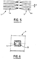
- the corresponding ends of the coupling means and corresponding complementary disengageable means of the sleeve and of the body and / or of the shaft are tapered and the sleeve has a determined course of angular displacement a between the body and the tree as shown in Figure 5.
- this stroke a corresponds to the pitch of these coupling and complementary means in order to facilitate the engagement of these means in the position of blocking of the shaft in the body regardless of their relative position when the locking mechanism is released. by the user.
- these elastic means designated by the reference 20 can be interposed between the locking mechanism and more particularly the finger 5 thereof and the sleeve 6 and more particularly the edges of a recess of the latter intended to receive this finger, to urge the latter in the intermediate or neutral position of its travel and allow it to move angularly in one direction or the other to obtain immediate engagement of the disengageable coupling and complementary means of the sleeve and of the shaft when the locking mechanism is triggered by the user, which guarantees immediate locking of the shaft in the body, that is to say without the need for angular displacement of the shaft as this was the case with the devices of the state of the art.
Landscapes
- Engineering & Computer Science (AREA)
- Mechanical Engineering (AREA)
- Steering Controls (AREA)
Applications Claiming Priority (2)
| Application Number | Priority Date | Filing Date | Title |
|---|---|---|---|
| FR9401230 | 1994-02-03 | ||
| FR9401230A FR2715619B1 (fr) | 1994-02-03 | 1994-02-03 | Dispositif antivol pour ensemble de colonne de direction notamment de véhicule automobile. |
Publications (1)
| Publication Number | Publication Date |
|---|---|
| EP0666205A1 true EP0666205A1 (de) | 1995-08-09 |
Family
ID=9459750
Family Applications (1)
| Application Number | Title | Priority Date | Filing Date |
|---|---|---|---|
| EP95400210A Withdrawn EP0666205A1 (de) | 1994-02-03 | 1995-02-01 | Diebstahlsicherung für Lenksäule, insbesondere von Kraftfahrzeugen |
Country Status (2)
| Country | Link |
|---|---|
| EP (1) | EP0666205A1 (de) |
| FR (1) | FR2715619B1 (de) |
Cited By (2)
| Publication number | Priority date | Publication date | Assignee | Title |
|---|---|---|---|---|
| EP0721869A1 (de) * | 1995-01-12 | 1996-07-17 | YMOS AKTIENGESELLSCHAFT Industrieprodukte | Verriegelungsvorrichtung für Kraftfahrzeuge |
| DE19752519A1 (de) * | 1997-11-27 | 1999-06-10 | Bosch Gmbh Robert | Verriegelungseinrichtung für Lenkungen von Kraftfahrzeugen |
Citations (1)
| Publication number | Priority date | Publication date | Assignee | Title |
|---|---|---|---|---|
| EP0539127A1 (de) * | 1991-10-22 | 1993-04-28 | Dick Lucien Chitolie | Steuereinrichtung mit Diebstahlssicherung in Fahrzeugen |
-
1994
- 1994-02-03 FR FR9401230A patent/FR2715619B1/fr not_active Expired - Fee Related
-
1995
- 1995-02-01 EP EP95400210A patent/EP0666205A1/de not_active Withdrawn
Patent Citations (1)
| Publication number | Priority date | Publication date | Assignee | Title |
|---|---|---|---|---|
| EP0539127A1 (de) * | 1991-10-22 | 1993-04-28 | Dick Lucien Chitolie | Steuereinrichtung mit Diebstahlssicherung in Fahrzeugen |
Cited By (3)
| Publication number | Priority date | Publication date | Assignee | Title |
|---|---|---|---|---|
| EP0721869A1 (de) * | 1995-01-12 | 1996-07-17 | YMOS AKTIENGESELLSCHAFT Industrieprodukte | Verriegelungsvorrichtung für Kraftfahrzeuge |
| DE19752519A1 (de) * | 1997-11-27 | 1999-06-10 | Bosch Gmbh Robert | Verriegelungseinrichtung für Lenkungen von Kraftfahrzeugen |
| US6298938B1 (en) | 1997-11-27 | 2001-10-09 | Robert Bosch Gmbh | Locking device for the steering system of motor vehicles |
Also Published As
| Publication number | Publication date |
|---|---|
| FR2715619B1 (fr) | 1996-05-03 |
| FR2715619A1 (fr) | 1995-08-04 |
Similar Documents
| Publication | Publication Date | Title |
|---|---|---|
| EP1302684B1 (de) | Drehverbindungseinrichtung für zwei teleskopische Wellen | |
| EP0559523B1 (de) | Einstellbare Lenksäuleneinheit für ein Kraftfahrzeug | |
| FR2822122A1 (fr) | Assemblage d'un etrier de colonne de direction avec un pignon de direction d'un vehicule automobile | |
| FR2892993A1 (fr) | Dispositif aerodynamique pour un vehicule automobile et vehicule automobile comportant au moins un tel dispositif aerodynamique. | |
| EP0281442A1 (de) | Einstellvorrichtung des Winkelstandes eines Lenkrades auf einer Fahrzeuglenksäule | |
| FR2707583A1 (fr) | Ensemble de colonne de direction rétractable axialement en cas de choc, notamment pour véhicule automobile. | |
| EP0666205A1 (de) | Diebstahlsicherung für Lenksäule, insbesondere von Kraftfahrzeugen | |
| EP0577499A1 (de) | Lenkstockschalter, insbesondere für Kraftfahrzeuge | |
| FR2747357A1 (fr) | Ensemble de colonne de direction a absorption d'energie de choc, notamment pour vehicule automobile | |
| EP0514232A1 (de) | Sicherheitsvorrichtung für die Blockierung eines Rotors bei einem gewaltsamen Öffnungsversuch, und Schloss mit einer solchen Vorrichtung | |
| EP0631912B1 (de) | Lenkradschloss für Kraftfahrzeuge | |
| FR2786520A1 (fr) | Verrou et agencement de ce verrou dans un support | |
| FR2715618A1 (fr) | Dispositif antivol pour ensemble de colonne de direction par exemple de véhicule automobile. | |
| FR2810382A1 (fr) | Dispositif d'assemblage d'un element rotatif d'un mecanisme de frein avec un moyen de roue de vehicule | |
| FR2702016A1 (fr) | Dispositif d'immobilisation temporaire de deux organes montés déplaçables l'un dans l'autre, d'un ensemble de colonne de direction de véhicule automobile. | |
| EP0569269A1 (de) | Diebstahlsichere Lenksäule, insbesondere für Kraftfahrzeuge | |
| FR2715906A1 (fr) | Dispositif de fixation d'un organe sur un arbre de direction notamment de véhicule automobile. | |
| FR2751605A1 (fr) | Dispositif de fixation d'un moyeu de volant de direction de vehicule, sur une extremite d'un arbre de direction | |
| FR2714126A1 (fr) | Palier de guidage d'un arbre de direction dans un corps de colonne, notamment pour véhicule automobile. | |
| FR2766441A1 (fr) | Antivol electrique comportant des moyens complementaires de blocage du pene | |
| EP0672573A1 (de) | Verstellbare Lenksäule, insbesondere für ein Kraftfahrzeug | |
| EP0734937B1 (de) | Sicherheitsverriegelung für eine einstellbare Lenksäule, insbesondere für Kraftfahrzeuge | |
| EP1757829A2 (de) | Vorrichtung zur Erzeugung eines vordefinierten Spannungszustands bei Bedienungsvorrichtung mit einem in eine Führungshülle eingelegten Kabel | |
| FR2764950A1 (fr) | Dispositif anti-boitement et anti-extraction d'un ensemble coulissant | |
| FR2724469A1 (fr) | Dispositif de blocage en rotation a limitation de couple, notamment pour colonne de direction de vehicule automobile |
Legal Events
| Date | Code | Title | Description |
|---|---|---|---|
| PUAI | Public reference made under article 153(3) epc to a published international application that has entered the european phase |
Free format text: ORIGINAL CODE: 0009012 |
|
| AK | Designated contracting states |
Kind code of ref document: A1 Designated state(s): BE CH DE ES FR GB IT LI LU NL SE |
|
| 17P | Request for examination filed |
Effective date: 19951117 |
|
| 17Q | First examination report despatched |
Effective date: 19961021 |
|
| STAA | Information on the status of an ep patent application or granted ep patent |
Free format text: STATUS: THE APPLICATION HAS BEEN WITHDRAWN |
|
| 18W | Application withdrawn |
Withdrawal date: 19970111 |