EP0666194A1 - Vehicle seat, convertible into a childseat - Google Patents
Vehicle seat, convertible into a childseat Download PDFInfo
- Publication number
- EP0666194A1 EP0666194A1 EP94119780A EP94119780A EP0666194A1 EP 0666194 A1 EP0666194 A1 EP 0666194A1 EP 94119780 A EP94119780 A EP 94119780A EP 94119780 A EP94119780 A EP 94119780A EP 0666194 A1 EP0666194 A1 EP 0666194A1
- Authority
- EP
- European Patent Office
- Prior art keywords
- seat
- cushion
- seat part
- vehicle seat
- lever
- Prior art date
- Legal status (The legal status is an assumption and is not a legal conclusion. Google has not performed a legal analysis and makes no representation as to the accuracy of the status listed.)
- Granted
Links
- 230000008878 coupling Effects 0.000 claims abstract description 10
- 238000010168 coupling process Methods 0.000 claims abstract description 10
- 238000005859 coupling reaction Methods 0.000 claims abstract description 10
- 230000009194 climbing Effects 0.000 claims description 2
- 238000013016 damping Methods 0.000 description 1
- 230000001419 dependent effect Effects 0.000 description 1
Images
Classifications
-
- B—PERFORMING OPERATIONS; TRANSPORTING
- B60—VEHICLES IN GENERAL
- B60N—SEATS SPECIALLY ADAPTED FOR VEHICLES; VEHICLE PASSENGER ACCOMMODATION NOT OTHERWISE PROVIDED FOR
- B60N2/00—Seats specially adapted for vehicles; Arrangement or mounting of seats in vehicles
- B60N2/24—Seats specially adapted for vehicles; Arrangement or mounting of seats in vehicles for particular purposes or particular vehicles
- B60N2/30—Non-dismountable or dismountable seats storable in a non-use position, e.g. foldable spare seats
- B60N2/3081—Seats convertible into parts of the seat cushion or the back-rest or disapppearing therein, e.g. for children
- B60N2/3086—Disappearing in a recess of the cushion
-
- B—PERFORMING OPERATIONS; TRANSPORTING
- B60—VEHICLES IN GENERAL
- B60N—SEATS SPECIALLY ADAPTED FOR VEHICLES; VEHICLE PASSENGER ACCOMMODATION NOT OTHERWISE PROVIDED FOR
- B60N2/00—Seats specially adapted for vehicles; Arrangement or mounting of seats in vehicles
- B60N2/24—Seats specially adapted for vehicles; Arrangement or mounting of seats in vehicles for particular purposes or particular vehicles
- B60N2/30—Non-dismountable or dismountable seats storable in a non-use position, e.g. foldable spare seats
- B60N2/3088—Non-dismountable or dismountable seats storable in a non-use position, e.g. foldable spare seats characterised by the mechanical link
- B60N2/309—Non-dismountable or dismountable seats storable in a non-use position, e.g. foldable spare seats characterised by the mechanical link rods
Definitions
- the invention relates to a vehicle seat, convertible into a child seat, with the features specified in the preamble of claim 1.
- Such a vehicle seat is known from EP-A-0 286 542, which has a seat part upholstery formed from two parts, in which the front upholstery part can be pivoted from a normal position via the rear upholstery part into a child seat position via two side pivoting levers. It is particularly disadvantageous that the height of the front cushion part cannot be changed in the child seat position, so that smaller and larger children, for whom the elevated seat part cushion is too high or too low, cannot find a comfortable seat position on the child seat.
- the invention has for its object to develop a vehicle seat with the features in the preamble of claim 1 so that a child seat can be formed with different seat heights.
- the front or rear pivoting lever or both pivoting levers are only to be held in the relevant angular position by the holding device at a desired height of the seat part cushion.
- the holding device can lock the relevant pivot lever in different ways, for example by self-locking a drive.
- the front lower end of the front pivot lever is adjustable approximately in the longitudinal direction of the seat. To adjust the height of the seat cushion, only this end of the front pivoting lever is to be held in a desired longitudinal position by the holding device. This can take place, for example, via a latching link on the seat part, which has latching points into which the front lower end of the front pivot lever engages in the various longitudinal positions of the seats.
- the swivel levers each arranged on a seat side region can be connected to suitable lever arms via a coupling rod.
- the front swivel lever held in place no further holding device is required to fix the seat cushion in the set height.
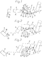
- the vehicle seat shown in its normal position in FIG. 1 can be converted into a child seat.
- it contains a backrest 1 which can be tilted in a known manner.
- three upholstery parts 3, 4, 5 arranged one behind the other are supported on the seat part 2, which is adjustable in length and height and inclination, for example.
- the rear upholstery part 3 forms a seat part cushion 3 ', which is supported in each case in a seat side area by means of two lateral pivot levers 6, 6', which allow the seat part cushion 3 'to be adjusted in height.
- the two lateral pivot levers 6, 6 ' are each pivoted about a seat transverse axis 7, 7', 7 '' approximately one behind the other on the seat part cushion 3 'and the rear pivot lever 6' on its other end region on the seat part 2.
- the front lower end 8 of the front pivot lever 6 is adjustable for adjusting the height of the seat cushion 3 'approximately in the longitudinal direction of the seat and can be locked in the various longitudinal positions on the seat part 2 by a holding device.
- the holding device is formed by a latching device 9 which is supported on the seat part 2 and has latching points 10, 10 ', 10'',10'''' arranged one behind the other in the longitudinal direction of the seat.
- the front lower end 8 of the front pivot lever 6 can engage in each of the locking points 10, 10 ', 10'',10'''. If, for example, the front lower end 8 engages in the latching point 10 ', the seat part cushion 3' is in a first child seat position which is raised to the normal position. If, however, the end 8 engages in the locking point 10 ′′ or 10 ′′ ′′, the seat part cushion 3 ′ is in a further elevated child seat position, the highest child seat position being reached when the end 8 engages in the rest area 10 '''. In the normal position of the vehicle seat shown in FIG. 1, the front lower end 8 of the front pivot lever 6 engages in the locking point 10.
- the rear pivot lever 6 ' has a lever arm 12 projecting via its articulation point (transverse seat axis 7') on the seat part cushion 3 ', to which one end of a coupling rod 11 is articulated, which at its other end also between the seat part cushion 3' and the seat part 2 the front pivot lever 6 is articulated.
- the coupling rod 11 forms part of the holding device which, when the end 8 engages in a latching point 10, 10 ', 10'',10''', sufficiently holds the pivot levers 6, 6 'and thus the seat part upholstery 3'.
- the coupling rod 11 and the rear pivoting lever 6 'and on the other hand the coupling rod 11 and the front pivoting lever 6 each form an over-center joint which, for example in the event of accidental longitudinal forces on the seat part cushion 3', stresses it downwards to the seat part 2, which causes this Seat part cushion 3 'remains held.
- a wall section 13 ′ of the locking point 10 engages around the end 8 accordingly.
- the latching points 10, 10 ′, 10 ′′, 10 ′′ ′′ which are shown only symbolically and thus in a simplified manner in the exemplary embodiment, are formed in the exemplary embodiment by recesses in a latching link 13, which interact with a corresponding counter surface on the front pivot lever 6.
- the front lower end 8 of the front pivot lever 6 engages in the locking point 10 ', whereby a child seat is formed in a first height position of the seat cushion 3'. Due to the not to scale representation, the front pivot lever 6 is in an unfavorable angular position in this child seat position in a practical embodiment, it may not be sufficient to prevent the seat transverse axis 7 from being displaced downward into the over-center position. In a practical embodiment, the front pivot lever 6 in a position corresponding to FIG. 2 has an angle to the vertical direction that is smaller than the angular position shown. It can be seen in the figure that the front cushion part 5 can be pivoted forward about a front lower transverse axis 14 from the normal position shown in FIG.
- the middle cushion part 4 is only loosely placed on the seat part 2 and, at its rear edge region, is connected to the front edge of the seat part cushion 3 ′ such that it can pivot about a transverse axis 17.
- the front lower edge of the middle cushion part 4 rests on the seat part 2 at all heights of the seat part cushion 3 '.
- a stop could be provided on the upholstery part 4 or 5, which limits the angular position of the upholstery part 4 at least in the maximum height position of the upholstery part 3 '.
- the seat part cushion 3 ' is at its maximum height.
- the latching link 13 used in the exemplary embodiment can be designed to be closed in an approximately vertical longitudinal plane of the seat, so that in this case the end 8 of the pivoting lever 6 does not differ significantly from the latching points 10, 10 ', 10'' , 10 '''can be removed.
- the invention can also be implemented in a manner that differs from the exemplary embodiment.
- the design of the pivot lever and the coupling rod as well as the number of locking points and the shape of the locking link are to be specified according to design and / or stylistic considerations. More or less than three cushion parts can be supported on the seat part. It is also not necessary for the seat part cushion to form the rearmost cushion part.
- the two pivot levers can also be arranged approximately in parallel and the holding device can have a releasable locking device which, in different angular positions of the pivot levers, locks an associated front or rear pivot lever in the different angular positions.
- the locking device can also be formed by self-locking of a motor drive, which causes the associated pivot lever to pivot into the desired angular position.
- a spring or damping element can be provided which engages on the seat part element, on a pivoting lever or on the coupling rod.
- the upholstery parts can, for example, be connected to an assigned seat shell.
- the respective laterally opposite pivot levers can be connected to form a common pivot lever which is arranged under the seat cushion, for example in the center of the side of the vehicle seat.
Landscapes
- Engineering & Computer Science (AREA)
- Aviation & Aerospace Engineering (AREA)
- Transportation (AREA)
- Mechanical Engineering (AREA)
- Seats For Vehicles (AREA)
Abstract
Description
Die Erfindung betrifft einen Fahrzeugsitz, umwandelbar in einen Kindersitz, mit den im Oberbegriff des Patentanspruchs 1 angegebenen Merkmalen.The invention relates to a vehicle seat, convertible into a child seat, with the features specified in the preamble of claim 1.
Ein derartiger Fahrzeugsitz ist durch die EP-A-0 286 542 bekannt, der eine aus zwei Teilen gebildete Sitzteilpolsterung aufweist, bei der das vordere Polsterteil über jeweils zwei seitliche Schwenkhebel aus einer Normallage über das hintere Polsterteil in eine Kindersitzstellung schwenkbar ist. Besonders nachteilig ist, daß die Höhenlage des vorderen Polsterteiles in der Kindersitzstellung nicht zu verändern ist, so daß kleinere und größere Kinder, für die das erhöhte Sitzteilpolster zu hoch oder zu niedrig ist, auf dem Kindersitz keine bequeme Sitzstellung finden.Such a vehicle seat is known from EP-A-0 286 542, which has a seat part upholstery formed from two parts, in which the front upholstery part can be pivoted from a normal position via the rear upholstery part into a child seat position via two side pivoting levers. It is particularly disadvantageous that the height of the front cushion part cannot be changed in the child seat position, so that smaller and larger children, for whom the elevated seat part cushion is too high or too low, cannot find a comfortable seat position on the child seat.
Der Erfindung liegt die Aufgabe zugrunde, einen Fahrzeugsitz mit den Merkmalen im Oberbegriff des Patentanspruches 1 so weiterzubilden, daß ein Kindersitz mit unterschiedlichen Sitzhöhen gebildet werden kann.The invention has for its object to develop a vehicle seat with the features in the preamble of claim 1 so that a child seat can be formed with different seat heights.
Diese Aufgabe ist durch die im Patentanspruch 1 angegebenen Merkmale gelöst. Besonders vorteilhaft ist, daß lediglich in einer gewünschten Höhe des Sitzteilpolsters der vordere oder hintere Schwenkhebel oder beide Schwenkhebel in der betreffenden Winkellage von der Halteeinrichtung festzuhalten sind. Die Halteeinrichtung kann auf unterschiedliche Weise, beispielsweise durch Selbsthemmung eines Antriebs, den betreffenden Schwenkhebel arretieren. Bei einer besonders vorteilhaften Ausführung ist das vordere untere Ende des vorderen Schwenkhebels etwa in Sitzlängsrichtung verstellbar. Zur Einstellung der Höhenlage des Sitzteilpolsters ist lediglich dieses Ende des vorderen Schwenkhebels in einer gewünschten Sitzlängslage von der Halteeinrichtung festzuhalten. Dies kann beispielsweise über eine Rastkulisse an dem Sitzteil erfolgen, die Raststellen aufweist, in die in den verschiedenen Sitzlängslagen das vordere untere Ende des vorderen Schwenkhebels einrastet. Dabei können die jeweils an einem Sitzseitenbereich angeordneten Schwenkhebel an geeigneten Hebelarmen über eine Koppelstange verbunden sein. In diesem Fall ist bei festgehaltenem vorderen Schwenkhebel zur Fixierung des Sitzteilpolster in der eingestellten Höhenlage keine weitere Halteeinrichtung erforderlich.This object is achieved by the features specified in claim 1. It is particularly advantageous that the front or rear pivoting lever or both pivoting levers are only to be held in the relevant angular position by the holding device at a desired height of the seat part cushion. The holding device can lock the relevant pivot lever in different ways, for example by self-locking a drive. In a particularly advantageous embodiment, the front lower end of the front pivot lever is adjustable approximately in the longitudinal direction of the seat. To adjust the height of the seat cushion, only this end of the front pivoting lever is to be held in a desired longitudinal position by the holding device. This can take place, for example, via a latching link on the seat part, which has latching points into which the front lower end of the front pivot lever engages in the various longitudinal positions of the seats. In this case, the swivel levers each arranged on a seat side region can be connected to suitable lever arms via a coupling rod. In this case, with the front swivel lever held in place, no further holding device is required to fix the seat cushion in the set height.
Vorteilhafte Ausgestaltungen der Erfindung sind Gegenstand von Unteransprüchen.Advantageous embodiments of the invention are the subject of dependent claims.
Ein Ausführungsbeispiel der Erfindung wird anhand einer Zeichnung näher erläutert. Es zeigen
- Figur 1
- den Fahrzeugsitz in seiner für einen Erwachsenen benutzbaren Normallage,
Figur 2- den in einen Kindersitz umgewandelten Fahrzeugsitz und
Figur 3- eine
Figur 2 entsprechende Ansicht in maximaler Hochlage des Sitzteilpolsters.
- Figure 1
- the vehicle seat in its normal position that can be used by an adult,
- Figure 2
- the vehicle seat converted into a child seat and
- Figure 3
- a view corresponding to Figure 2 in the maximum high position of the seat cushion.
Der in Figur 1 in seiner Normallage dargestellte Fahrzeugsitz ist in einen Kindersitz umwandelbar. Er enthält bei dem Ausführungsbeispiel eine Rückenlehne 1, die in bekannter Weise neigungseinstellbar ist. Auf dem beispielsweise längsverstellbaren sowie höhen- und neigungseinstellbaren Sitzteil 2 sind bei dem Ausführungsbeispiel drei hintereinander angeordnete Polsterteile 3, 4, 5 abgestützt. Das hintere Polsterteil 3 bildet ein Sitzteilpolster 3', das jeweils in einem Sitzseitenbereich über zwei seitliche Schwenkhebel 6, 6' abgestützt ist, die eine Höheneinstellung des Sitzteilpolsters 3' ermöglichen. Die beiden seitlichen Schwenkhebel 6, 6' sind hierzu jeweils um eine Sitzquerachse 7, 7', 7'' schwenkbar etwa hintereinander an dem Sitzteilpolster 3' und der hintere Schwenkhebel 6' an seinem anderen Endbereich an dem Sitzteil 2 angelenkt. Das vordere untere Ende 8 des vorderen Schwenkhebels 6 ist zur Einstellung der Höhenlage des Sitzteilpolsters 3' etwa in Sitzlängsrichtung verstellbar und von einer Halteeinrichtung in den verschiedenen Längslagen an dem Sitzteil 2 arretierbar. Die Halteeinrichtung ist bei dem Ausführungsbeispiel durch eine an dem Sitzteil 2 abgestützte Rasteinrichtung 9 mit etwa in Sitzlängsrichtung hintereinander angeordneten Raststellen 10, 10', 10'', 10''' gebildet. Das vordere untere Ende 8 des vorderen Schwenkhebels 6 kann in jede der Raststellen 10, 10', 10'', 10''' eingreifen. Greift beispielsweise das vordere untere Ende 8 in die Raststelle 10' ein, so befindet sich das Sitzteilpolster 3' in einer ersten, zur Normallage erhöhten Kindersitzstellung. Greift dagegen das Ende 8 in die Raststelle 10'' oder 10''' ein, befindet sich das Sitzteilpolster 3' in einer weiter erhöhten Kindersitzstellung, wobei die höchste Kindersitzstellung erreicht ist, wenn das Ende 8 in die Raststelle 10''' eingreift. In der in Figur 1 dargestellten Normallage des Fahrzeugsitzes greift das vordere untere Ende 8 des vorderen Schwenkhebels 6 in die Raststelle 10 ein. Der hintere Schwenkhebel 6' weist einen über seine Anlenkstelle (Sitzquerachse 7') an dem Sitzteilpolster 3' vorstehenden Hebelarm 12 auf, an dem ein Ende einer Koppelstange 11 angelenkt ist, die an ihrem anderen Ende zwischen dem Sitzteilpolster 3' und dem Sitzteil 2 mit dem vorderen Schwenkhebel 6 gelenkig verbunden ist. Die Koppelstange 11 bildet einen Teil der Halteeinrichtung, die bei in eine Raststelle 10, 10', 10'', 10''' eingreifendem Ende 8 die Schwenkhebel 6, 6' und damit die Sitzteilpolsterung 3' ausreichend festhält. In der dargestellten Normallage bilden einerseits die Koppelstange 11 und der hintere Schwenkhebel 6' sowie andererseits die Koppelstange 11 und der vordere Schwenkhebel 6 jeweils ein Übertotpunktgelenk, die beispielsweise bei unfallbedingten Längskräften an dem Sitzteilpolster 3' dieses nach unten zu dem Sitzteil 2 belasten, wodurch das Sitzteilpolster 3' festgehalten bleibt. Um bei einer derartigen Belastung ein Herausverlagern des Endes 8 aus der Raststelle 10 zu verhindern, umgreift ein Wandabschnitt 13' der Raststelle 10 das Ende 8 entsprechend. Die bei dem Ausführungsbeispiel lediglich symbolisch und damit vereinfacht dargestellten Raststellen 10, 10', 10'', 10''' sind bei dem Ausführungsbeispiel durch Ausnehmungen in einer Rastkulisse 13 gebildet, die mit einer entsprechenden Gegenfläche an dem vorderen Schwenkhebel 6 zusammenwirken.The vehicle seat shown in its normal position in FIG. 1 can be converted into a child seat. In the exemplary embodiment, it contains a backrest 1 which can be tilted in a known manner. In the exemplary embodiment, three
In Figur 2 greift das vordere untere Ende 8 des vorderen Schwenkhebels 6 in die Raststelle 10' ein, wodurch ein Kindersitz in einer ersten Höhenlage des Sitzteilpolsters 3' gebildet ist. Durch die nicht maßstabgerechte Darstellung befindet sich in dieser Kindersitzstellung der vordere Schwenkhebel 6 in einer ungünstigen Winkellage, die bei einer praktischen Ausführung möglicherweise nicht ausreichend ist, um eine Verlagerung der Sitzquerachse 7 nach unten in die Übertotpunktstellung zu verhindern. Bei einer praktischen Ausführung weist der vordere Schwenkhebel 6 in einer Figur 2 entsprechenden Stellung einen gegenüber der dargestellten Winkelstellung kleineren Winkel zur vertikalen Richtung auf. In der Figur ist erkennbar, daß das vordere Polsterteil 5 um eine vordere untere Querachse 14 aus der in Figur 1 dargestellten Normallage nach vorne in die in Figur 2 von einem Anschlag 15 an dem Sitzteil 2 begrenzte Winkellage schwenkbar ist. In dieser Winkellage bildet die in Normallage untere Seite 16 des vorderen Polsterteiles 5 eine Fußstütze und/oder eine Steighilfe für den Benutzer des Kindersitzes. Das mittlere Polsterteil 4 ist bei dem Ausführungsbeispiel lediglich lose auf das Sitzteil 2 aufgelegt und an seinem hinteren Randbereich etwa um eine Querachse 17 schwenkbar mit dem vorderen Rand des Sitzteilpolsters 3' verbunden. Bei dem Ausführungsbeispiel liegt in allen Höhenlagen des Sitzteilpolsters 3' der vordere untere Rand des mittleren Polsterteiles 4 auf dem Sitzteil 2 auf. Ebenso könnte an dem Polsterteil 4 oder 5 ein Anschlag vorgesehen sein, der zumindest in der maximalen Höhenlage des Sitzteilpolsters 3' die Winkellage des Polsterteiles 4 begrenzt.In Figure 2, the front
Ist der aus einem Fahrzeugsitz gebildete Kindersitz in die Figur 3 entsprechende Lage verstellt, befindet sich das Sitzteilpolster 3' in seiner maximalen Höhenlage. In der Figur ist noch angedeutet, daß die bei dem Ausführungsbeispiel verwendete Rastkulisse 13 in einer etwa vertikalen Sitzlängsebene geschlossen ausgebildet sein kann, so daß sich in diesem Fall das Ende 8 des Schwenkhebels 6 nicht wesentlich von den Raststellen 10, 10', 10'', 10''' entfernen kann.If the child seat formed from a vehicle seat is adjusted to the position corresponding to FIG. 3, the seat part cushion 3 'is at its maximum height. In the figure it is also indicated that the
Die Erfindung ist auch in einer von dem Ausführungsbeispiel abweichende Weise realisierbar. Die Ausbildung der Schwenkhebel und der Koppelstange sowie die Anzahl der Raststellen und die Form der Rastkulisse sind nach konstruktiven und/oder stilistischen Gesichtspunkten vorzugeben. An dem Sitzteil können mehr oder weniger als drei Polsterteile abgestützt sein. Es ist auch nicht erforderlich, daß das Sitzteilpolster das hinterste Polsterteil bildet. Die beiden Schwenkhebel können auch etwa parallel angeordnet sein und die Halteeinrichtung eine lösbare Verriegelungseinrichtung aufweisen, die in verschiedenen Winkelstellungen der Schwenkhebel einen zugeordneten vorderen oder hinteren Schwenkhebel in den verschiedenen Winkelstellungen arretiert. Die Verriegelungseinrichtung kann auch durch Selbsthemmung eines motorischen Antriebs gebildet sein, der ein Verschwenken des zugeordneten Schwenkhebels in die gewünschte Winkelstellung bewirkt. Um das Anheben des Sitzteilpolsters zu erleichtern bzw. das Absenken zu dämpfen, kann ein Feder- bzw. Dämpfungselement vorgesehen sein, das an dem Sitzteilelement, an einem Schwenkhebel oder an der Koppelstange angreift. Die Polsterteile können beispielsweise mit einer zugeordneten Sitzschale verbunden sein. Die jeweils seitlich gegenüberliegenden Schwenkhebel können zu einem gemeinsamen Schwenkhebel verbunden sein, der unter dem Sitzteilpolster beispielsweise in Seitenmitte des Fahrzeugsitzes angeordnet ist.The invention can also be implemented in a manner that differs from the exemplary embodiment. The design of the pivot lever and the coupling rod as well as the number of locking points and the shape of the locking link are to be specified according to design and / or stylistic considerations. More or less than three cushion parts can be supported on the seat part. It is also not necessary for the seat part cushion to form the rearmost cushion part. The two pivot levers can also be arranged approximately in parallel and the holding device can have a releasable locking device which, in different angular positions of the pivot levers, locks an associated front or rear pivot lever in the different angular positions. The locking device can also be formed by self-locking of a motor drive, which causes the associated pivot lever to pivot into the desired angular position. In order to facilitate the lifting of the seat part cushion or to dampen the lowering, a spring or damping element can be provided which engages on the seat part element, on a pivoting lever or on the coupling rod. The upholstery parts can, for example, be connected to an assigned seat shell. The respective laterally opposite pivot levers can be connected to form a common pivot lever which is arranged under the seat cushion, for example in the center of the side of the vehicle seat.
Claims (11)
Applications Claiming Priority (2)
| Application Number | Priority Date | Filing Date | Title |
|---|---|---|---|
| DE4402232 | 1994-01-26 | ||
| DE4402232A DE4402232A1 (en) | 1994-01-26 | 1994-01-26 | Vehicle seat, convertible into a child seat |
Publications (2)
| Publication Number | Publication Date |
|---|---|
| EP0666194A1 true EP0666194A1 (en) | 1995-08-09 |
| EP0666194B1 EP0666194B1 (en) | 1998-05-20 |
Family
ID=6508725
Family Applications (1)
| Application Number | Title | Priority Date | Filing Date |
|---|---|---|---|
| EP94119780A Expired - Lifetime EP0666194B1 (en) | 1994-01-26 | 1994-12-14 | Vehicle seat, convertible into a child seat |
Country Status (2)
| Country | Link |
|---|---|
| EP (1) | EP0666194B1 (en) |
| DE (2) | DE4402232A1 (en) |
Cited By (8)
| Publication number | Priority date | Publication date | Assignee | Title |
|---|---|---|---|---|
| EP0827863A2 (en) * | 1996-08-20 | 1998-03-11 | Araco Kabushiki Kaisha | Vehicle seat with height adjustable seat cushion |
| GB2368272A (en) * | 2000-10-23 | 2002-05-01 | Autoliv Dev | Weight responsive child safety seat |
| EP1223075A1 (en) * | 2001-01-05 | 2002-07-17 | Ford Global Technologies, Inc. | Automotive seat with height adjustable seat cushion |
| FR2854107A1 (en) * | 2003-04-23 | 2004-10-29 | Faurecia Sieges Automobile | Vehicle seat, has sitting surface with nose zone moved between top position in which it is aligned with sitting zone, and inclined position in which it under and inclined to sitting zone |
| WO2006075945A1 (en) | 2005-01-12 | 2006-07-20 | Autoliv Development Ab | An adjustable seat |
| FR2885564A1 (en) | 2005-05-10 | 2006-11-17 | Cera | Motor vehicle seat has base cushion made with lifting section to make a raised child's seat |
| US7815256B2 (en) | 2005-05-20 | 2010-10-19 | Autoliv Development,AB | Vehicle seat |
| EP2353930A1 (en) | 2010-01-27 | 2011-08-10 | Tofas Turk Otomobil Fabrikasi Anonim Sirketi | An integrated child seat |
Families Citing this family (2)
| Publication number | Priority date | Publication date | Assignee | Title |
|---|---|---|---|---|
| DE102004048931B3 (en) * | 2004-10-06 | 2005-07-28 | Grammer Automotive Gmbh | Vehicle seat with integrated child seat for safe carriage of child has at least two seat cushion sectors forming part of connecting rod transmission |
| CN107826003B (en) * | 2017-10-25 | 2024-04-12 | 清华大学苏州汽车研究院(相城) | Integrated automobile child safety seat |
Citations (5)
| Publication number | Priority date | Publication date | Assignee | Title |
|---|---|---|---|---|
| EP0286542A2 (en) * | 1987-04-10 | 1988-10-12 | Regie Nationale Des Usines Renault | Boxed seat for the transport of children in automotive vehicles |
| DE3922836A1 (en) * | 1988-01-14 | 1989-12-07 | Richard Ambros | Universal car seat for small and large passengers |
| EP0518726A1 (en) * | 1991-06-11 | 1992-12-16 | Bertrand Faure Automobile "B.F.A." | Device for raising a vehicle seat cushion, having a safety interlock |
| FR2692209A1 (en) * | 1992-06-15 | 1993-12-17 | Grammer Sable | Vehicle seat with integrated raising seat to form child's seat - has front section of seat base, which can be lifted by linkages to fit above fixed section of base, to form seat for baby or child |
| GB2278775A (en) * | 1993-06-11 | 1994-12-14 | Hammerstein Gmbh C Rob | Child seat for intergration into a vehicle seat |
Family Cites Families (2)
| Publication number | Priority date | Publication date | Assignee | Title |
|---|---|---|---|---|
| AU4381979A (en) * | 1978-06-19 | 1980-01-03 | Rainsfords Metal Products Pty. Ltd. | Vehicle child seat arrangement |
| FR2664215B1 (en) * | 1990-07-03 | 1994-11-10 | Europ Sieges Automobiles | METHOD FOR LOCKING UNDER LOAD OF A FOLDING CHILD SEAT FOR VEHICLE AND DEVICE FOR IMPLEMENTING SAME. |
-
1994
- 1994-01-26 DE DE4402232A patent/DE4402232A1/en not_active Withdrawn
- 1994-12-14 EP EP94119780A patent/EP0666194B1/en not_active Expired - Lifetime
- 1994-12-14 DE DE59406024T patent/DE59406024D1/en not_active Expired - Fee Related
Patent Citations (5)
| Publication number | Priority date | Publication date | Assignee | Title |
|---|---|---|---|---|
| EP0286542A2 (en) * | 1987-04-10 | 1988-10-12 | Regie Nationale Des Usines Renault | Boxed seat for the transport of children in automotive vehicles |
| DE3922836A1 (en) * | 1988-01-14 | 1989-12-07 | Richard Ambros | Universal car seat for small and large passengers |
| EP0518726A1 (en) * | 1991-06-11 | 1992-12-16 | Bertrand Faure Automobile "B.F.A." | Device for raising a vehicle seat cushion, having a safety interlock |
| FR2692209A1 (en) * | 1992-06-15 | 1993-12-17 | Grammer Sable | Vehicle seat with integrated raising seat to form child's seat - has front section of seat base, which can be lifted by linkages to fit above fixed section of base, to form seat for baby or child |
| GB2278775A (en) * | 1993-06-11 | 1994-12-14 | Hammerstein Gmbh C Rob | Child seat for intergration into a vehicle seat |
Cited By (14)
| Publication number | Priority date | Publication date | Assignee | Title |
|---|---|---|---|---|
| US5997083A (en) * | 1996-08-20 | 1999-12-07 | Araco Kabushiki Kaisha | Vehicle seat with height adjustable seat cushion |
| EP0827863A3 (en) * | 1996-08-20 | 1999-12-22 | Araco Kabushiki Kaisha | Vehicle seat with height adjustable seat cushion |
| EP0827863A2 (en) * | 1996-08-20 | 1998-03-11 | Araco Kabushiki Kaisha | Vehicle seat with height adjustable seat cushion |
| GB2368272B (en) * | 2000-10-23 | 2004-04-28 | Autoliv Dev | Improvements in or relating to a child safety seat |
| GB2368272A (en) * | 2000-10-23 | 2002-05-01 | Autoliv Dev | Weight responsive child safety seat |
| US6758520B2 (en) | 2001-01-05 | 2004-07-06 | Ford Global Technologies, Inc. | Adjustable height automotive seat |
| EP1223075A1 (en) * | 2001-01-05 | 2002-07-17 | Ford Global Technologies, Inc. | Automotive seat with height adjustable seat cushion |
| FR2854107A1 (en) * | 2003-04-23 | 2004-10-29 | Faurecia Sieges Automobile | Vehicle seat, has sitting surface with nose zone moved between top position in which it is aligned with sitting zone, and inclined position in which it under and inclined to sitting zone |
| US7093897B2 (en) | 2003-04-23 | 2006-08-22 | Faurecia Sieges D'automobile, S.A. | Automobile vehicle seat adaptable to accommodate a child |
| WO2006075945A1 (en) | 2005-01-12 | 2006-07-20 | Autoliv Development Ab | An adjustable seat |
| US7918503B2 (en) | 2005-01-12 | 2011-04-05 | Autoliv Development Ab | Adjustable seat |
| FR2885564A1 (en) | 2005-05-10 | 2006-11-17 | Cera | Motor vehicle seat has base cushion made with lifting section to make a raised child's seat |
| US7815256B2 (en) | 2005-05-20 | 2010-10-19 | Autoliv Development,AB | Vehicle seat |
| EP2353930A1 (en) | 2010-01-27 | 2011-08-10 | Tofas Turk Otomobil Fabrikasi Anonim Sirketi | An integrated child seat |
Also Published As
| Publication number | Publication date |
|---|---|
| DE59406024D1 (en) | 1998-06-25 |
| EP0666194B1 (en) | 1998-05-20 |
| DE4402232A1 (en) | 1995-07-27 |
Similar Documents
| Publication | Publication Date | Title |
|---|---|---|
| DE10215058C1 (en) | Headrest for aircraft passenger seat provided with inclination angle and height adjustment mechanisms | |
| DE19841363C1 (en) | Motor vehicle rear seat with foldable backrest and lowerable seat part | |
| DE19646470B4 (en) | Motor vehicle seat with a backrest and a seat | |
| DE10247131B4 (en) | vehicle seat | |
| DE19946174A1 (en) | Adjustable child or infant chair for use in a car has a recliner mounted on a base allowing adjustment of recline and seat level | |
| DE2823093A1 (en) | CHILD CAR SEAT | |
| DE19810768B4 (en) | office chair | |
| DE3139945A1 (en) | Seat, especially a motor-vehicle seat | |
| DE19635432A1 (en) | Adjustable backrest construction of pushchair | |
| EP1132294A2 (en) | Aircraft passenger seat | |
| EP1270315A2 (en) | Vehicle seat positioned on the floor | |
| EP0359962B1 (en) | Seat, particularly a motor car seat | |
| DE8507191U1 (en) | Adjustable vehicle seat | |
| DE102010014058A1 (en) | vehicle seat | |
| EP0666194A1 (en) | Vehicle seat, convertible into a childseat | |
| DE3617810C2 (en) | ||
| DE3404612A1 (en) | HEADREST OF A VEHICLE SEAT WITH TWO CARRIAGE BRACKETS ATTACHED TO THE SEATREST | |
| DE2102108A1 (en) | Seat, especially vehicle seat | |
| EP0518130B1 (en) | Vehicle seat with seat height and backrest adjustment | |
| DE3447040A1 (en) | Vertically adjustable vehicle seat | |
| DE4424096A1 (en) | Chair with lower frame, support and seat | |
| DE19914163A1 (en) | Seat for motor vehicle has backrest fastened via height-adjusting unit to longitudinally adjustable seat rail | |
| DE19522967B4 (en) | Integrable child seat for a motor vehicle seat | |
| DE10244293B4 (en) | Motor vehicle seat, in particular rear seat | |
| DE19617401C2 (en) | Vehicle seat with seat tilt adjustment |
Legal Events
| Date | Code | Title | Description |
|---|---|---|---|
| PUAI | Public reference made under article 153(3) epc to a published international application that has entered the european phase |
Free format text: ORIGINAL CODE: 0009012 |
|
| AK | Designated contracting states |
Kind code of ref document: A1 Designated state(s): DE FR GB IT |
|
| 17P | Request for examination filed |
Effective date: 19950707 |
|
| 17Q | First examination report despatched |
Effective date: 19961106 |
|
| GRAG | Despatch of communication of intention to grant |
Free format text: ORIGINAL CODE: EPIDOS AGRA |
|
| GRAG | Despatch of communication of intention to grant |
Free format text: ORIGINAL CODE: EPIDOS AGRA |
|
| GRAH | Despatch of communication of intention to grant a patent |
Free format text: ORIGINAL CODE: EPIDOS IGRA |
|
| GRAH | Despatch of communication of intention to grant a patent |
Free format text: ORIGINAL CODE: EPIDOS IGRA |
|
| GRAA | (expected) grant |
Free format text: ORIGINAL CODE: 0009210 |
|
| AK | Designated contracting states |
Kind code of ref document: B1 Designated state(s): DE FR GB IT |
|
| GBT | Gb: translation of ep patent filed (gb section 77(6)(a)/1977) |
Effective date: 19980520 |
|
| ET | Fr: translation filed | ||
| REF | Corresponds to: |
Ref document number: 59406024 Country of ref document: DE Date of ref document: 19980625 |
|
| ITF | It: translation for a ep patent filed | ||
| PLBE | No opposition filed within time limit |
Free format text: ORIGINAL CODE: 0009261 |
|
| STAA | Information on the status of an ep patent application or granted ep patent |
Free format text: STATUS: NO OPPOSITION FILED WITHIN TIME LIMIT |
|
| 26N | No opposition filed | ||
| PGFP | Annual fee paid to national office [announced via postgrant information from national office to epo] |
Ref country code: GB Payment date: 20011212 Year of fee payment: 8 |
|
| PGFP | Annual fee paid to national office [announced via postgrant information from national office to epo] |
Ref country code: FR Payment date: 20011228 Year of fee payment: 8 |
|
| REG | Reference to a national code |
Ref country code: GB Ref legal event code: IF02 |
|
| PGFP | Annual fee paid to national office [announced via postgrant information from national office to epo] |
Ref country code: DE Payment date: 20020129 Year of fee payment: 8 |
|
| PG25 | Lapsed in a contracting state [announced via postgrant information from national office to epo] |
Ref country code: GB Free format text: LAPSE BECAUSE OF NON-PAYMENT OF DUE FEES Effective date: 20021214 |
|
| PG25 | Lapsed in a contracting state [announced via postgrant information from national office to epo] |
Ref country code: DE Free format text: LAPSE BECAUSE OF NON-PAYMENT OF DUE FEES Effective date: 20030701 |
|
| GBPC | Gb: european patent ceased through non-payment of renewal fee |
Effective date: 20021214 |
|
| PG25 | Lapsed in a contracting state [announced via postgrant information from national office to epo] |
Ref country code: FR Free format text: LAPSE BECAUSE OF NON-PAYMENT OF DUE FEES Effective date: 20030901 |
|
| REG | Reference to a national code |
Ref country code: FR Ref legal event code: ST |
|
| PG25 | Lapsed in a contracting state [announced via postgrant information from national office to epo] |
Ref country code: IT Free format text: LAPSE BECAUSE OF NON-PAYMENT OF DUE FEES Effective date: 20051214 |