EP0666189A1 - Castor assembly - Google Patents
Castor assembly Download PDFInfo
- Publication number
- EP0666189A1 EP0666189A1 EP95300481A EP95300481A EP0666189A1 EP 0666189 A1 EP0666189 A1 EP 0666189A1 EP 95300481 A EP95300481 A EP 95300481A EP 95300481 A EP95300481 A EP 95300481A EP 0666189 A1 EP0666189 A1 EP 0666189A1
- Authority
- EP
- European Patent Office
- Prior art keywords
- wheel
- cam
- castor assembly
- housing
- swivel
- Prior art date
- Legal status (The legal status is an assumption and is not a legal conclusion. Google has not performed a legal analysis and makes no representation as to the accuracy of the status listed.)
- Granted
Links
- 235000004443 Ricinus communis Nutrition 0.000 title claims abstract description 32
- 238000010276 construction Methods 0.000 abstract description 3
- 229910000831 Steel Inorganic materials 0.000 description 3
- 230000015572 biosynthetic process Effects 0.000 description 3
- 238000005755 formation reaction Methods 0.000 description 3
- 230000002093 peripheral effect Effects 0.000 description 3
- 238000003825 pressing Methods 0.000 description 3
- 239000010959 steel Substances 0.000 description 3
- 230000000712 assembly Effects 0.000 description 2
- 238000000429 assembly Methods 0.000 description 2
- 230000000694 effects Effects 0.000 description 2
- 238000001125 extrusion Methods 0.000 description 2
- 238000003466 welding Methods 0.000 description 2
- 239000004677 Nylon Substances 0.000 description 1
- 238000003475 lamination Methods 0.000 description 1
- 238000003754 machining Methods 0.000 description 1
- 239000000463 material Substances 0.000 description 1
- 239000002184 metal Substances 0.000 description 1
- 238000000034 method Methods 0.000 description 1
- 229920001778 nylon Polymers 0.000 description 1
- 229920002635 polyurethane Polymers 0.000 description 1
- 239000004814 polyurethane Substances 0.000 description 1
- 230000000717 retained effect Effects 0.000 description 1
- 125000006850 spacer group Chemical group 0.000 description 1
Images


Classifications
-
- B—PERFORMING OPERATIONS; TRANSPORTING
- B60—VEHICLES IN GENERAL
- B60B—VEHICLE WHEELS; CASTORS; AXLES FOR WHEELS OR CASTORS; INCREASING WHEEL ADHESION
- B60B33/00—Castors in general; Anti-clogging castors
- B60B33/02—Castors in general; Anti-clogging castors with disengageable swivel action, i.e. comprising a swivel locking mechanism
- B60B33/021—Castors in general; Anti-clogging castors with disengageable swivel action, i.e. comprising a swivel locking mechanism combined with braking of castor wheel
-
- B—PERFORMING OPERATIONS; TRANSPORTING
- B60—VEHICLES IN GENERAL
- B60B—VEHICLE WHEELS; CASTORS; AXLES FOR WHEELS OR CASTORS; INCREASING WHEEL ADHESION
- B60B33/00—Castors in general; Anti-clogging castors
- B60B33/0036—Castors in general; Anti-clogging castors characterised by type of wheels
- B60B33/0039—Single wheels
-
- B—PERFORMING OPERATIONS; TRANSPORTING
- B60—VEHICLES IN GENERAL
- B60B—VEHICLE WHEELS; CASTORS; AXLES FOR WHEELS OR CASTORS; INCREASING WHEEL ADHESION
- B60B33/00—Castors in general; Anti-clogging castors
- B60B33/0047—Castors in general; Anti-clogging castors characterised by details of the rolling axle
- B60B33/0049—Castors in general; Anti-clogging castors characterised by details of the rolling axle the rolling axle being horizontal
-
- B—PERFORMING OPERATIONS; TRANSPORTING
- B60—VEHICLES IN GENERAL
- B60B—VEHICLE WHEELS; CASTORS; AXLES FOR WHEELS OR CASTORS; INCREASING WHEEL ADHESION
- B60B33/00—Castors in general; Anti-clogging castors
- B60B33/006—Castors in general; Anti-clogging castors characterised by details of the swivel mechanism
- B60B33/0065—Castors in general; Anti-clogging castors characterised by details of the swivel mechanism characterised by details of the swivel axis
- B60B33/0068—Castors in general; Anti-clogging castors characterised by details of the swivel mechanism characterised by details of the swivel axis the swivel axis being vertical
-
- B—PERFORMING OPERATIONS; TRANSPORTING
- B60—VEHICLES IN GENERAL
- B60B—VEHICLE WHEELS; CASTORS; AXLES FOR WHEELS OR CASTORS; INCREASING WHEEL ADHESION
- B60B33/00—Castors in general; Anti-clogging castors
- B60B33/0078—Castors in general; Anti-clogging castors characterised by details of the wheel braking mechanism
- B60B33/0081—Castors in general; Anti-clogging castors characterised by details of the wheel braking mechanism acting on tire tread
-
- B—PERFORMING OPERATIONS; TRANSPORTING
- B60—VEHICLES IN GENERAL
- B60B—VEHICLE WHEELS; CASTORS; AXLES FOR WHEELS OR CASTORS; INCREASING WHEEL ADHESION
- B60B33/00—Castors in general; Anti-clogging castors
- B60B33/02—Castors in general; Anti-clogging castors with disengageable swivel action, i.e. comprising a swivel locking mechanism
- B60B33/025—Castors in general; Anti-clogging castors with disengageable swivel action, i.e. comprising a swivel locking mechanism by using form-fit, e.g. front teeth
-
- B—PERFORMING OPERATIONS; TRANSPORTING
- B60—VEHICLES IN GENERAL
- B60B—VEHICLE WHEELS; CASTORS; AXLES FOR WHEELS OR CASTORS; INCREASING WHEEL ADHESION
- B60B33/00—Castors in general; Anti-clogging castors
- B60B33/0047—Castors in general; Anti-clogging castors characterised by details of the rolling axle
- B60B33/0057—Castors in general; Anti-clogging castors characterised by details of the rolling axle the rolling axle being offset from swivel axis
-
- B—PERFORMING OPERATIONS; TRANSPORTING
- B60—VEHICLES IN GENERAL
- B60B—VEHICLE WHEELS; CASTORS; AXLES FOR WHEELS OR CASTORS; INCREASING WHEEL ADHESION
- B60B33/00—Castors in general; Anti-clogging castors
- B60B33/006—Castors in general; Anti-clogging castors characterised by details of the swivel mechanism
- B60B33/0065—Castors in general; Anti-clogging castors characterised by details of the swivel mechanism characterised by details of the swivel axis
- B60B33/0073—Castors in general; Anti-clogging castors characterised by details of the swivel mechanism characterised by details of the swivel axis the swivel axis being symmetrical to wheel or wheels
-
- B—PERFORMING OPERATIONS; TRANSPORTING
- B60—VEHICLES IN GENERAL
- B60Y—INDEXING SCHEME RELATING TO ASPECTS CROSS-CUTTING VEHICLE TECHNOLOGY
- B60Y2200/00—Type of vehicle
- B60Y2200/40—Special vehicles
- B60Y2200/49—Movable platforms, Load ramps, e.g. working platforms
Definitions
- This invention relates to a castor assembly and particularly to a castor assembly of the kind which incorporates a brake for the castor wheel.
- Conventional castor assemblies for supporting, for example movable scaffolding towers or trolleys of various kinds may incorporate means for moving the wheel axle into either a running position, offset from the vertical swivel axis of the castor assembly, or into a locked position where, or close to where, the wheel axis intersects the vertical swivel axis to stabilise the assembly against swivelling under horizontal loads.
- a brake By the application of a brake to the castor wheel in the locked position, rotation of the wheel is prevented.
- One object of the present invention is to provide an improved castor assembly of the kind described.
- a castor assembly comprises a housing, a swivel enabling the housing to rotate about a vertical axis, a cam located adjacent the swivel, a wheel carrier pivotally secured to the housing by means of a horizontal pivot offset from said vertical axis, having a wheel mounted thereon so as to be rotatable about a horizontal axis and being capable of pivoting movement to cause the wheel to move into and out of a locked position wherein the cam is brakingly engaged with the wheel to prevent rotation thereof about said horizontal axis and with the swivel to prevent rotation of the housing about the vertical axis.
- the carrier comprises two arms, each one extending from opposite sides of the housing so that by depression of one arm the carrier is moved about its pivot to move the wheel into the locked position and by depression of the other arm the carrier is moved about its pivot to move the wheel out of said locked position i.e. into a running position.
- the movement of the wheel into said locked position causes movement of the cam into braking engagement with the periphery thereof and into braking engagement with the swivel.
- the cam when the wheel is in the running position the cam is in contact with the wheel periphery in order to dislodge any foreign matter, such as a piece of grit which may have become attached thereto.
- the cam may be rotary, loosely mounted on a horizontally disposed camshaft, and may comprise a cylinder i.e. having a circular cross-section, mounted eccentrically on the cam shaft.
- the cam may have other suitable cross-sectional shapes.
- the cam may be lobed in shape and be formed either by extrusion or by welding two cylinders of different diameters together, the smaller diameter cylinder providing the lobe.
- the cam may be provided with at least one formation e.g. one or more ribs and/or grooves to provide edges for gripping the wheel periphery when in braking engagement.
- the shaft may be horizontally supported by attachment to two side plates of the housing or two brackets secured to a horizontal top plate of the housing.
- the castor assembly 10 of the first embodiment illustrated in Figures 1-4 comprises a housing 11 having a swivel mounting 12 by which it is rotatably secured to a cylindrical steel plug 13 of suitable diameter to enter and be fixed in the lower end of, for example, a scaffolding tube forming part of a movable tower.
- a swivel mounting 12 by which it is rotatably secured to a cylindrical steel plug 13 of suitable diameter to enter and be fixed in the lower end of, for example, a scaffolding tube forming part of a movable tower.
- socket or top plate type of mounting may be employed to suit operational requirements.
- the swivel mounting 12 which is generally conventional in its construction, comprises a pair of steel discs 17 and 18, pressed to suitable profiles so as to provide races for upper and lower ball bearings 20 and 21 respectively to enable the housing 11 to be rotatably secured to the plug 13 via a suitably pressed annular portion 25 of a top plate 60 of the housing 11.
- An elastomeric seal 67 is provided between the top disc 17 and the top plate 60.
- the swivel mounting 12 is secured to the plug by means of a spigot portion 26 of the plug which is star rivetted at its lower end 27 against a washer 28.
- the housing 11 which is originally produced from a flat plate by a series of pressing operations has a top horizontal plate 60 and two downwardly extending side plates 30, 31 to which a wheel carrier 32 is secured by a means of a horizontal pivot constituted by a pair of shoulder rivets 33, 34 fastened to the side plates 30, 31 respectively.
- the wheel 51 is generally conventional being made of suitable material to support the loading capacity of the castor assembly.
- the wheel has a nylon central portion 52 and a polyurethane tyre 53 mechanically keyed to its circumference.
- the wheel is mounted on an axle bush 56, the ends of which are held in horizontal apertures 54, 55 one in each of the side plates 30, 31 by an axle bolt 61, washers 57 and nuts 58.
- a circular cross-section camshaft 81 Adjacent to, but to one side of, the spigot portion 26 of the plug 13 within the upper portion of the housing 11 is a circular cross-section camshaft 81 secured at its ends in two holes 87, 88 one in each of the side plates 30, 31 by circlips or other suitable means. Alternatively the ends of the cam shaft 81 may be secured in holes in brackets (not shown) welded to the underside of the top plate 60.
- the camshaft 81 is disposed horizontally i.e. parallel to the wheel axle 56.
- Loosely mounted on the camshaft is a rotary cam 84 which provides a braking impediment. As shown in Figures 1-4 the cam is in the form of a cylinder, i.e.
- the cam may be cylindrical but provided with two longitudinally extending grooves 96,97, each one parallel to the cam axis. These grooves define a ridge 95 therebetween.
- This cam shape is shown in Figure 5.
- the cam 84 is maintained in a central position adjacent the wheel periphery on the camshaft 81 by spacer tubes 85 secured to the camshaft by circlips or grub screws 86 and each extending between one end of the cam and the nearer side plate 30 or 31.
- the two side plates 30,31 of the housing are formed with pairs of dimples 99,93, each projecting inwardly towards the carrier, at the positions shown in the drawings.
- the wheel carrier 32 comprises a pair of generally triangular side members 37, 38 which are sheet metal pressings pivotally mounted in parallel relationship on the rivets 33, 34. This construction enables the wheel carrier to be moved about a horizontal pivot axis defined by the rivets.
- the ends of the side members 37, 38 are secured together respectively by welding or by nut and bolt assemblies 40, 41 (as shown) and pedal plates 42, 43 with or without side flanges 44, 45 (only two shown) to unite the side members in a rigid structure.
- This arrangement thus provides the carrier with a pair of arms 46, 47 each one extending on opposite sides of the housing as shown in Figure 1.
- Each of the pedal plates is to provide e.g. by an embossed or indented message thereon, an indication to the operator of which of the arms needs to be pressed downwardly to release or brake the castor assembly.
- Each side member 37, 38 of the carrier is formed with elongated, shaped apertures, 49 one in each side member, through which the axle bush 56 of the castor wheel 51 passes.
- the shaped apertures are each formed with curved sides 91 and shoulders 92 with purposes which will be described later, and the apertures have narrow portions adjacent the shoulders.
- the left-hand arm 47 is in the downwards position and the right-hand arm 46 is elevated.
- the wheel axle is at the right hand end of the horizontal apertures 54,55 (and thus spaced apart by a distance B from the vertical swivel axis) and in the lower end of each shaped aperture 49, being maintained there by the lower of the two shoulders 92, and by the effect of the lower dimples 93 on the side plates projecting above the top of the adjacent side member 37 or 38 of the wheel carrier.
- the wheel carrier On lowering the right-hand arm 46 to the position shown in dotted outline in Figure 1 (and thus automatically raising the left-hand arm 47) the wheel carrier rotates about the horizontal pivot axis defined by the rivets 33,34 the side members 37,38 pressing against and past the dimples 99,93 on the side plates.
- the wheel axle 56 is caused to move by action of the curved sides 91 of the apertures 49 to the left-hand end of the horizontal apertures 54,55 in the housing 11 beyond the upper shoulder 92 in the aperture.
- the axle is retained in this position by the upper shoulder and the effect of the upper dimples 99 on the side plates projecting below the side member 37 or 38 of the wheel carrier. This camming action moves the wheel horizontally so that its axis is directly beneath the swivel axis.
- the periphery of the tyre on the wheel moves into contact with the cam 84 to rotate it through approximately 90° about the horizontal axis of the cam shaft 81 and to bring it into contact with the lower steel disc 18 of the swivel mounting.
- the cam action is generated by the outer surface of the tyre rotating the loosely mounted cam 84 so as to be wedged between the said tyre surface and the disc 18. This brakes both the wheel and the housing with respect to the swivel.
- the wheel is held in this brake position by the action of the shoulder 92 on the shaped apertures 49 and the brake is only released by depression of the pedal 43 on the arm 47. Reverse rotation of the cam is restricted by the shaft 90.
- the cam is as shown in Figure 5
- the two grooves 96,97 and the ridge 95 face to the right as shown in Figures 1 and 2 when the castor wheel 51 is in the running position.
- the cam rotates through about 90° so that the ridge 95 presses against the peripheral surface of the tyre 53, and the curved surface 98 opposite the ridge 95, presses against the lower surface of the plate 18, thus braking the wheel and housing with respect to the swivel.
- the castor assembly of the second embodiment illustrated in Figures 6-9 is similar to that of the first embodiment and the same reference numerals for like features.
- the cam 101 has a lobed shape generally having a tear-drop or pear-drop cross-section.
- the lobed portion 104 i.e. having the smaller radius of curvature, hangs downward, directly beneath the cam shaft 81, when the castor wheel 51 is in the running position.
- the lobed portion 104 is in contact with the outer periphery of the tyre 53 (as illustrated in Figure 9) so as to dislodge any foreign matter, such as a piece of grit, which may become attached thereto.
- the lobed cam 101 may alternatively be provided with two parallel, longitudinally extending grooves 106,107 defining a ridge 105, therebetween.
- the lobe of this cam would be directed to the left (if included in Figures 6,7 and 9), the ridge 105 would press against the tyre peripheral surface and the curved surface 108 opposite the ridge 105 would press against the under surface of the plate 18, thus braking the wheel and housing with respect to the swivel.
- the castor assembly of the third embodiment shown in Figure 11 is similar to the assembly of the second embodiment.
- lobed cam 200 comprises two cylindrical rods, one 201 having a larger diameter than the other 202, welded together to have the cross-sectional shape as shown.
- the larger of the two rods is formed by a machining process with two grooves 203,204 extending parallel to the rod axis and defining a rib 205 therebetween.
- These formations of grooves and ribs are positioned on the outer surface of the cam 200 to contact the periphery of the tyre 53 on the wheel 51 when the wheel and carrier are in the braked position as shown in dotted outline in Figure 11.
- These formations provide gripping edges which enhance the braking action.
- this shape of cam may be formed by an extrusion process, or from stamped laminations fastened together.
- the cam 200 is also positioned relative to the wheel 51 so that it is not possible for reverse rotation to occur i.e. to the right (as shown in Figure 11) whereby the lobe 202 is positioned beneath the spigot portion 26, thus avoiding the need for a retaining shaft 90 as shown in Figure 3.
- the pedal plates comprise flat plates 220,221, with upturned edges 222,223, welded to the ends of the arms 37,38.
- the castor assembly in accordance with the invention is robust, simple and easily operated.
- the wheel carrier may be moved from a running position to a locked position or vice versa by an operator applying downwards foot pressure to the pedal plate on appropriate arm 37, 38 of the wheel carrier.
Landscapes
- Engineering & Computer Science (AREA)
- Mechanical Engineering (AREA)
- Braking Arrangements (AREA)
- Legs For Furniture In General (AREA)
- Movable Scaffolding (AREA)
Abstract
Description
- This invention relates to a castor assembly and particularly to a castor assembly of the kind which incorporates a brake for the castor wheel.
- Conventional castor assemblies for supporting, for example movable scaffolding towers or trolleys of various kinds may incorporate means for moving the wheel axle into either a running position, offset from the vertical swivel axis of the castor assembly, or into a locked position where, or close to where, the wheel axis intersects the vertical swivel axis to stabilise the assembly against swivelling under horizontal loads. By the application of a brake to the castor wheel in the locked position, rotation of the wheel is prevented.
- One object of the present invention is to provide an improved castor assembly of the kind described.
- According to the invention a castor assembly comprises a housing, a swivel enabling the housing to rotate about a vertical axis, a cam located adjacent the swivel, a wheel carrier pivotally secured to the housing by means of a horizontal pivot offset from said vertical axis, having a wheel mounted thereon so as to be rotatable about a horizontal axis and being capable of pivoting movement to cause the wheel to move into and out of a locked position wherein the cam is brakingly engaged with the wheel to prevent rotation thereof about said horizontal axis and with the swivel to prevent rotation of the housing about the vertical axis.
- Preferably the carrier comprises two arms, each one extending from opposite sides of the housing so that by depression of one arm the carrier is moved about its pivot to move the wheel into the locked position and by depression of the other arm the carrier is moved about its pivot to move the wheel out of said locked position i.e. into a running position.
- Preferably the movement of the wheel into said locked position causes movement of the cam into braking engagement with the periphery thereof and into braking engagement with the swivel.
- Preferably, when the wheel is in the running position the cam is in contact with the wheel periphery in order to dislodge any foreign matter, such as a piece of grit which may have become attached thereto.
- The cam may be rotary, loosely mounted on a horizontally disposed camshaft, and may comprise a cylinder i.e. having a circular cross-section, mounted eccentrically on the cam shaft. The cam may have other suitable cross-sectional shapes. For example the cam may be lobed in shape and be formed either by extrusion or by welding two cylinders of different diameters together, the smaller diameter cylinder providing the lobe. Further the cam may be provided with at least one formation e.g. one or more ribs and/or grooves to provide edges for gripping the wheel periphery when in braking engagement.
- The shaft may be horizontally supported by attachment to two side plates of the housing or two brackets secured to a horizontal top plate of the housing.
- Three embodiments of the invention will now be described by way of example only with reference to the accompanying drawings of which;-
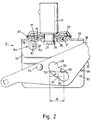
- Figure 1 shows a side view of a castor assembly according to a first embodiment of the invention;
- Figure 2 shows a cross-section of the assembly of Figure 1, the wheel being in the running position, the wheel and other parts being omitted for clarity;
- Figure 3 shows an end view in direction of arrow A in of Figure 2;
- Figure 4 shows a view similar to that in Figure 2 but with the wheel in the braked position, and, in dotted outline, in the unbraked position, but other parts being omitted for clarity;
- Figure 5 shows a perspective view of an alternative form of cam for inclusion in the assembly of the first embodiment;
- Figure 6 shows a side view of a castor assembly according to a second embodiment of the invention;
- Figure 7 shows a cross-section of the assembly of Figure 6, the wheel being in the running position, the wheel and other parts being omitted for clarity;
- Figure 8 shows an end view on arrow B in Figure 7;
- Figure 9 shows a view similar to that of Figure 7 but with the wheel in the braked position, and, in dotted outline, on the unbraked position with the cam in contact therewith, other parts being omitted for clarity; and
- Figure 10 shows a perspective view of an alternative form of cam for inclusion in the assembly of the second embodiment; and
- Figure 11 shows a partial side view, partial cross-sectional view of a castor assembly according to a third embodiment of the invention.
- The
castor assembly 10 of the first embodiment illustrated in Figures 1-4 comprises ahousing 11 having aswivel mounting 12 by which it is rotatably secured to acylindrical steel plug 13 of suitable diameter to enter and be fixed in the lower end of, for example, a scaffolding tube forming part of a movable tower. Alternatively, socket or top plate type of mounting may be employed to suit operational requirements. - The
swivel mounting 12 which is generally conventional in its construction, comprises a pair ofsteel discs lower ball bearings housing 11 to be rotatably secured to theplug 13 via a suitably pressedannular portion 25 of atop plate 60 of thehousing 11. Anelastomeric seal 67 is provided between thetop disc 17 and thetop plate 60. Theswivel mounting 12 is secured to the plug by means of aspigot portion 26 of the plug which is star rivetted at itslower end 27 against awasher 28. - The
housing 11 which is originally produced from a flat plate by a series of pressing operations has a tophorizontal plate 60 and two downwardly extendingside plates wheel carrier 32 is secured by a means of a horizontal pivot constituted by a pair ofshoulder rivets side plates wheel 51 is generally conventional being made of suitable material to support the loading capacity of the castor assembly. In this embodiment, the wheel has a nyloncentral portion 52 and apolyurethane tyre 53 mechanically keyed to its circumference. The wheel is mounted on an axle bush 56, the ends of which are held inhorizontal apertures side plates axle bolt 61,washers 57 andnuts 58. When the axle is at one end of eachhorizontal aperture - Adjacent to, but to one side of, the
spigot portion 26 of theplug 13 within the upper portion of thehousing 11 is acircular cross-section camshaft 81 secured at its ends in twoholes side plates cam shaft 81 may be secured in holes in brackets (not shown) welded to the underside of thetop plate 60. Thecamshaft 81 is disposed horizontally i.e. parallel to the wheel axle 56. Loosely mounted on the camshaft is arotary cam 84 which provides a braking impediment. As shown in Figures 1-4 the cam is in the form of a cylinder, i.e. having a circular cross-section, eccentrically mounted on thecamshaft 81. Alternatively, the cam may be cylindrical but provided with two longitudinally extendinggrooves ridge 95 therebetween. This cam shape is shown in Figure 5. Thecam 84 is maintained in a central position adjacent the wheel periphery on thecamshaft 81 byspacer tubes 85 secured to the camshaft by circlips orgrub screws 86 and each extending between one end of the cam and thenearer side plate retaining shaft 90 secured at its ends in two holes, one in eachside plate 30,31 (or the brackets, if the cam is mounted thereon) by circlips or other suitable means. - The two
side plates dimples - The
wheel carrier 32 comprises a pair of generallytriangular side members rivets side members bolt assemblies 40, 41 (as shown) andpedal plates side flanges 44, 45 (only two shown) to unite the side members in a rigid structure. This arrangement thus provides the carrier with a pair ofarms - Each
side member castor wheel 51 passes. The shaped apertures are each formed withcurved sides 91 andshoulders 92 with purposes which will be described later, and the apertures have narrow portions adjacent the shoulders. - In the running position, as shown in Figure 1, the left-
hand arm 47 is in the downwards position and the right-hand arm 46 is elevated. The wheel axle is at the right hand end of thehorizontal apertures 54,55 (and thus spaced apart by a distance B from the vertical swivel axis) and in the lower end of eachshaped aperture 49, being maintained there by the lower of the twoshoulders 92, and by the effect of thelower dimples 93 on the side plates projecting above the top of theadjacent side member - On lowering the right-
hand arm 46 to the position shown in dotted outline in Figure 1 (and thus automatically raising the left-hand arm 47) the wheel carrier rotates about the horizontal pivot axis defined by therivets side members dimples curved sides 91 of theapertures 49 to the left-hand end of thehorizontal apertures housing 11 beyond theupper shoulder 92 in the aperture. The axle is retained in this position by the upper shoulder and the effect of theupper dimples 99 on the side plates projecting below theside member cam 84 to rotate it through approximately 90° about the horizontal axis of thecam shaft 81 and to bring it into contact with thelower steel disc 18 of the swivel mounting. The cam action is generated by the outer surface of the tyre rotating the loosely mountedcam 84 so as to be wedged between the said tyre surface and thedisc 18. This brakes both the wheel and the housing with respect to the swivel. The wheel is held in this brake position by the action of theshoulder 92 on theshaped apertures 49 and the brake is only released by depression of thepedal 43 on thearm 47. Reverse rotation of the cam is restricted by theshaft 90. - If the cam is as shown in Figure 5, the two
grooves ridge 95 face to the right as shown in Figures 1 and 2 when thecastor wheel 51 is in the running position. When the wheel is moved to the locked position, as shown in Figure 4, the cam rotates through about 90° so that theridge 95 presses against the peripheral surface of thetyre 53, and thecurved surface 98 opposite theridge 95, presses against the lower surface of theplate 18, thus braking the wheel and housing with respect to the swivel. - The castor assembly of the second embodiment illustrated in Figures 6-9 is similar to that of the first embodiment and the same reference numerals for like features. However in the second embodiment the
cam 101 has a lobed shape generally having a tear-drop or pear-drop cross-section. Thelobed portion 104, i.e. having the smaller radius of curvature, hangs downward, directly beneath thecam shaft 81, when thecastor wheel 51 is in the running position. Thelobed portion 104 is in contact with the outer periphery of the tyre 53 (as illustrated in Figure 9) so as to dislodge any foreign matter, such as a piece of grit, which may become attached thereto. When thewheel 51 is moved to the locked position, as shown on Figure 9, the cam is rotated through about 90° so as to take up the position shown, thelobed portion 104 being directed to the left. The cam thus becomes wedged between the peripheral surface of thetyre 53 and the lower surface of theplate 18, thus braking the wheel and the housing with respect to the swivel. Reverse rotation of thecam 101 may be restricted by thelobe 104 touching the wheel surface or by the cam touching thepin 90. - As shown in Figure 10, the
lobed cam 101 may alternatively be provided with two parallel, longitudinally extending grooves 106,107 defining aridge 105, therebetween. When the wheel is moved to the locked position the lobe of this cam would be directed to the left (if included in Figures 6,7 and 9), theridge 105 would press against the tyre peripheral surface and thecurved surface 108 opposite theridge 105 would press against the under surface of theplate 18, thus braking the wheel and housing with respect to the swivel. - The castor assembly of the third embodiment shown in Figure 11 is similar to the assembly of the second embodiment. In this embodiment to
lobed cam 200 comprises two cylindrical rods, one 201 having a larger diameter than the other 202, welded together to have the cross-sectional shape as shown. The larger of the two rods is formed by a machining process with two grooves 203,204 extending parallel to the rod axis and defining arib 205 therebetween. These formations of grooves and ribs are positioned on the outer surface of thecam 200 to contact the periphery of thetyre 53 on thewheel 51 when the wheel and carrier are in the braked position as shown in dotted outline in Figure 11. These formations provide gripping edges which enhance the braking action. Alternatively this shape of cam may be formed by an extrusion process, or from stamped laminations fastened together. - The
cam 200 is also positioned relative to thewheel 51 so that it is not possible for reverse rotation to occur i.e. to the right (as shown in Figure 11) whereby the lobe 202 is positioned beneath thespigot portion 26, thus avoiding the need for a retainingshaft 90 as shown in Figure 3. - In this embodiment the pedal plates comprise flat plates 220,221, with upturned edges 222,223, welded to the ends of the
arms - The castor assembly in accordance with the invention is robust, simple and easily operated. The wheel carrier may be moved from a running position to a locked position or vice versa by an operator applying downwards foot pressure to the pedal plate on
appropriate arm
Claims (9)
Applications Claiming Priority (6)
| Application Number | Priority Date | Filing Date | Title |
|---|---|---|---|
| GB9421576 | 1994-01-26 | ||
| GB9402136 | 1994-02-04 | ||
| GB9402136A GB9402136D0 (en) | 1994-02-04 | 1994-02-04 | Castor assembly |
| GB9403035A GB9403035D0 (en) | 1994-02-04 | 1994-02-17 | Castor assembly |
| GB9403035 | 1994-02-17 | ||
| GB9421576A GB9421576D0 (en) | 1994-02-04 | 1994-10-26 | Castor assembly |
Publications (2)
| Publication Number | Publication Date |
|---|---|
| EP0666189A1 true EP0666189A1 (en) | 1995-08-09 |
| EP0666189B1 EP0666189B1 (en) | 1998-06-10 |
Family
ID=27267043
Family Applications (1)
| Application Number | Title | Priority Date | Filing Date |
|---|---|---|---|
| EP95300481A Expired - Lifetime EP0666189B1 (en) | 1994-02-04 | 1995-01-26 | Castor assembly |
Country Status (5)
| Country | Link |
|---|---|
| US (1) | US5509506A (en) |
| EP (1) | EP0666189B1 (en) |
| DE (2) | DE666189T1 (en) |
| ES (1) | ES2075827T3 (en) |
| GB (1) | GB9421576D0 (en) |
Cited By (3)
| Publication number | Priority date | Publication date | Assignee | Title |
|---|---|---|---|---|
| EP0706903A1 (en) * | 1994-10-11 | 1996-04-17 | TELLURE ROTA S.p.A. | An orientatable and lockable wheel set for moving mobile working platforms, mobile scaffolding and the like |
| EP0733495A2 (en) * | 1995-03-23 | 1996-09-25 | Wicke GmbH + Co. KG | Castor for mobile working-platforms, scaffolds or similar |
| NL1036660C2 (en) * | 2009-03-04 | 2009-12-30 | One For Wheels B V | Scaffold wheel for aluminum scaffolding, has mobile support device pivotally connected to wheel support frame, and shaft sleeve with ends extending through wheel carrier plates, where wheel support frame is coupled to rotation axis |
Families Citing this family (9)
| Publication number | Priority date | Publication date | Assignee | Title |
|---|---|---|---|---|
| US5829096A (en) * | 1996-01-29 | 1998-11-03 | Perry; Eugene D. | Locking caster |
| US6163924A (en) * | 1997-05-23 | 2000-12-26 | Graco Children's Products Inc. | Swivel caster assembly with releasable lock mechanism |
| US5937967A (en) * | 1997-09-03 | 1999-08-17 | Morgan; Frank O. | Mobile scaffolding apparatus with retractable wheels |
| US6286184B1 (en) * | 1999-07-30 | 2001-09-11 | Perry Manufacturing, Inc. | Castor with brake and locking mechanism |
| DE202006016576U1 (en) * | 2006-10-26 | 2008-03-06 | Sonnendorfer, Horst | immobilizer |
| US9579241B2 (en) | 2012-10-12 | 2017-02-28 | Steelcase Inc. | Support arrangement with activation mechanism |
| CN205044427U (en) * | 2015-09-28 | 2016-02-24 | 胡冠礼 | Novel area brake truckle |
| JP6921541B2 (en) * | 2017-02-07 | 2021-08-18 | キヤノン株式会社 | Fall prevention device and feeding device |
| US11654715B2 (en) | 2017-05-08 | 2023-05-23 | Snap-On Incorporated | Caster wheel |
Citations (6)
| Publication number | Priority date | Publication date | Assignee | Title |
|---|---|---|---|---|
| CH298456A (en) * | 1951-12-08 | 1954-05-15 | Schnetzler Anton | Swivel castor with braking device. |
| US3162888A (en) * | 1961-09-28 | 1964-12-29 | Firm Tente Rollen Gmbh & Compa | Lock type caster |
| FR2537505A1 (en) * | 1982-12-08 | 1984-06-15 | Schulte Soehne Gmbh Co A | Brake lever for swivel castor |
| EP0364732A1 (en) * | 1988-10-14 | 1990-04-25 | TENTE-ROLLEN GmbH & Co. | Caster |
| EP0413197A1 (en) | 1989-08-16 | 1991-02-20 | Wicke GmbH & Co. | Castor for platforms, scaffoldings or similar |
| DE9314939U1 (en) * | 1993-10-01 | 1993-12-16 | Haion Caster Industrial Co., Ltd., Taipeh/T'ai-pei | Roller for moving structures |
Family Cites Families (3)
| Publication number | Priority date | Publication date | Assignee | Title |
|---|---|---|---|---|
| FR1345858A (en) * | 1962-12-19 | 1963-12-13 | Brake for wheels and castors | |
| GB1449292A (en) * | 1973-09-04 | 1976-09-15 | Thomas Ltd Martin | Castors |
| JPS55156702A (en) * | 1979-05-25 | 1980-12-06 | Natsuo Morita | Wheel device |
-
1994
- 1994-10-26 GB GB9421576A patent/GB9421576D0/en active Pending
-
1995
- 1995-01-26 ES ES95300481T patent/ES2075827T3/en not_active Expired - Lifetime
- 1995-01-26 DE DE0666189T patent/DE666189T1/en active Pending
- 1995-01-26 EP EP95300481A patent/EP0666189B1/en not_active Expired - Lifetime
- 1995-01-26 DE DE69502844T patent/DE69502844T2/en not_active Expired - Fee Related
- 1995-02-01 US US08/382,397 patent/US5509506A/en not_active Expired - Fee Related
Patent Citations (7)
| Publication number | Priority date | Publication date | Assignee | Title |
|---|---|---|---|---|
| CH298456A (en) * | 1951-12-08 | 1954-05-15 | Schnetzler Anton | Swivel castor with braking device. |
| US3162888A (en) * | 1961-09-28 | 1964-12-29 | Firm Tente Rollen Gmbh & Compa | Lock type caster |
| FR2537505A1 (en) * | 1982-12-08 | 1984-06-15 | Schulte Soehne Gmbh Co A | Brake lever for swivel castor |
| EP0364732A1 (en) * | 1988-10-14 | 1990-04-25 | TENTE-ROLLEN GmbH & Co. | Caster |
| EP0413197A1 (en) | 1989-08-16 | 1991-02-20 | Wicke GmbH & Co. | Castor for platforms, scaffoldings or similar |
| US5012550A (en) | 1989-08-16 | 1991-05-07 | Wicke Gmbh & Co. | Caster with brake |
| DE9314939U1 (en) * | 1993-10-01 | 1993-12-16 | Haion Caster Industrial Co., Ltd., Taipeh/T'ai-pei | Roller for moving structures |
Cited By (4)
| Publication number | Priority date | Publication date | Assignee | Title |
|---|---|---|---|---|
| EP0706903A1 (en) * | 1994-10-11 | 1996-04-17 | TELLURE ROTA S.p.A. | An orientatable and lockable wheel set for moving mobile working platforms, mobile scaffolding and the like |
| EP0733495A2 (en) * | 1995-03-23 | 1996-09-25 | Wicke GmbH + Co. KG | Castor for mobile working-platforms, scaffolds or similar |
| EP0733495A3 (en) * | 1995-03-23 | 1997-10-22 | Wicke Gmbh & Co Kg | Castor for mobile working-platforms, scaffolds or similar |
| NL1036660C2 (en) * | 2009-03-04 | 2009-12-30 | One For Wheels B V | Scaffold wheel for aluminum scaffolding, has mobile support device pivotally connected to wheel support frame, and shaft sleeve with ends extending through wheel carrier plates, where wheel support frame is coupled to rotation axis |
Also Published As
| Publication number | Publication date |
|---|---|
| ES2075827T3 (en) | 1998-08-01 |
| GB9421576D0 (en) | 1994-12-14 |
| ES2075827T1 (en) | 1995-10-16 |
| EP0666189B1 (en) | 1998-06-10 |
| DE69502844D1 (en) | 1998-07-16 |
| DE666189T1 (en) | 1995-12-14 |
| DE69502844T2 (en) | 1998-11-26 |
| US5509506A (en) | 1996-04-23 |
Similar Documents
| Publication | Publication Date | Title |
|---|---|---|
| US5509506A (en) | Castor brake assembly | |
| KR100336383B1 (en) | Supporting device for fixing | |
| US4143442A (en) | Castor with a brake device | |
| CA1078753A (en) | Brake assembly | |
| US5497856A (en) | Locking caster brake assembly | |
| US2262433A (en) | Caster | |
| US4449268A (en) | Caster wheel brake having an overcenter latch | |
| JPS6229353Y2 (en) | ||
| US2900659A (en) | Caster locking mechanism | |
| GB2286116A (en) | A braked castor assembley eg. for a scaffold tower | |
| JP2004508236A (en) | caster | |
| US5884956A (en) | Modified railroad wheel and axle assembly | |
| US5402864A (en) | Castor brake assembly | |
| GB2183468A (en) | Castor assemblies | |
| CN211280493U (en) | Double-brake universal castor | |
| EP0352380B2 (en) | Castor | |
| CN217532405U (en) | Truckle that braking effect is good | |
| GB2099693A (en) | Improvements in or relating to castors | |
| GB2187946A (en) | Castor assemblies | |
| US3945472A (en) | Lever actuated brake assembly | |
| JP7061248B2 (en) | Brake mechanism | |
| US4006800A (en) | Lever actuated brake assembly | |
| JP2590983Y2 (en) | Brake device for mobile scaffolding wheel | |
| EP3747668B1 (en) | Caster | |
| CN108297617B (en) | Caster pedal rod braking system |
Legal Events
| Date | Code | Title | Description |
|---|---|---|---|
| PUAI | Public reference made under article 153(3) epc to a published international application that has entered the european phase |
Free format text: ORIGINAL CODE: 0009012 |
|
| AK | Designated contracting states |
Kind code of ref document: A1 Designated state(s): DE ES FR GB IT SE |
|
| 17P | Request for examination filed |
Effective date: 19950616 |
|
| EL | Fr: translation of claims filed | ||
| REG | Reference to a national code |
Ref country code: ES Ref legal event code: BA2A Ref document number: 2075827 Country of ref document: ES Kind code of ref document: T1 |
|
| DET | De: translation of patent claims | ||
| 17Q | First examination report despatched |
Effective date: 19960919 |
|
| GRAG | Despatch of communication of intention to grant |
Free format text: ORIGINAL CODE: EPIDOS AGRA |
|
| GRAG | Despatch of communication of intention to grant |
Free format text: ORIGINAL CODE: EPIDOS AGRA |
|
| GRAH | Despatch of communication of intention to grant a patent |
Free format text: ORIGINAL CODE: EPIDOS IGRA |
|
| GRAH | Despatch of communication of intention to grant a patent |
Free format text: ORIGINAL CODE: EPIDOS IGRA |
|
| GRAA | (expected) grant |
Free format text: ORIGINAL CODE: 0009210 |
|
| AK | Designated contracting states |
Kind code of ref document: B1 Designated state(s): DE ES FR GB IT SE |
|
| REF | Corresponds to: |
Ref document number: 69502844 Country of ref document: DE Date of ref document: 19980716 |
|
| REG | Reference to a national code |
Ref country code: ES Ref legal event code: FG2A Ref document number: 2075827 Country of ref document: ES Kind code of ref document: T3 |
|
| ITF | It: translation for a ep patent filed | ||
| PG25 | Lapsed in a contracting state [announced via postgrant information from national office to epo] |
Ref country code: SE Free format text: LAPSE BECAUSE OF FAILURE TO SUBMIT A TRANSLATION OF THE DESCRIPTION OR TO PAY THE FEE WITHIN THE PRESCRIBED TIME-LIMIT Effective date: 19980910 |
|
| ET | Fr: translation filed | ||
| PG25 | Lapsed in a contracting state [announced via postgrant information from national office to epo] |
Ref country code: GB Free format text: LAPSE BECAUSE OF NON-PAYMENT OF DUE FEES Effective date: 19990126 |
|
| PG25 | Lapsed in a contracting state [announced via postgrant information from national office to epo] |
Ref country code: ES Free format text: LAPSE BECAUSE OF NON-PAYMENT OF DUE FEES Effective date: 19990127 |
|
| PLBE | No opposition filed within time limit |
Free format text: ORIGINAL CODE: 0009261 |
|
| STAA | Information on the status of an ep patent application or granted ep patent |
Free format text: STATUS: NO OPPOSITION FILED WITHIN TIME LIMIT |
|
| 26N | No opposition filed | ||
| GBPC | Gb: european patent ceased through non-payment of renewal fee |
Effective date: 19990126 |
|
| PG25 | Lapsed in a contracting state [announced via postgrant information from national office to epo] |
Ref country code: FR Free format text: LAPSE BECAUSE OF NON-PAYMENT OF DUE FEES Effective date: 19990930 |
|
| PG25 | Lapsed in a contracting state [announced via postgrant information from national office to epo] |
Ref country code: DE Free format text: LAPSE BECAUSE OF NON-PAYMENT OF DUE FEES Effective date: 19991103 |
|
| REG | Reference to a national code |
Ref country code: FR Ref legal event code: ST |
|
| REG | Reference to a national code |
Ref country code: ES Ref legal event code: FD2A Effective date: 20000210 |
|
| PG25 | Lapsed in a contracting state [announced via postgrant information from national office to epo] |
Ref country code: IT Free format text: LAPSE BECAUSE OF NON-PAYMENT OF DUE FEES;WARNING: LAPSES OF ITALIAN PATENTS WITH EFFECTIVE DATE BEFORE 2007 MAY HAVE OCCURRED AT ANY TIME BEFORE 2007. THE CORRECT EFFECTIVE DATE MAY BE DIFFERENT FROM THE ONE RECORDED. Effective date: 20050126 |