EP0665312A1 - Shedding mechanism providing four warp yarns positions in a loom - Google Patents
Shedding mechanism providing four warp yarns positions in a loom Download PDFInfo
- Publication number
- EP0665312A1 EP0665312A1 EP95420020A EP95420020A EP0665312A1 EP 0665312 A1 EP0665312 A1 EP 0665312A1 EP 95420020 A EP95420020 A EP 95420020A EP 95420020 A EP95420020 A EP 95420020A EP 0665312 A1 EP0665312 A1 EP 0665312A1
- Authority
- EP
- European Patent Office
- Prior art keywords
- pulley
- frame
- cord
- block
- hooks
- Prior art date
- Legal status (The legal status is an assumption and is not a legal conclusion. Google has not performed a legal analysis and makes no representation as to the accuracy of the status listed.)
- Granted
Links
Images
Classifications
-
- D—TEXTILES; PAPER
- D03—WEAVING
- D03C—SHEDDING MECHANISMS; PATTERN CARDS OR CHAINS; PUNCHING OF CARDS; DESIGNING PATTERNS
- D03C3/00—Jacquards
- D03C3/12—Multiple-shed jacquards, i.e. jacquards which move warp threads to several different heights, e.g. for weaving pile fabrics
Definitions
- the present invention relates to an armor mechanism making it possible to bring warp yarns into four different positions by means of two claw frames movable vertically.
- This armor mechanism includes two neighboring crowd-forming devices which each have two hooks movable vertically under the effect of knives which move in opposition in a back-and-forth movement.
- the hooks of each device are joined by a cord passing around one of the pulleys constituting the block.
- a pulley mounted idly on a fixed axis relative to the mechanical frame Between the second pulley of the mittens of each device is placed a pulley mounted idly on a fixed axis relative to the mechanical frame, while a cord whose one end is anchored in the frame first surrounds the second pulley of the muffle of the first crowd formation device, then the idler pulley mounted on the fixed axis and finally the second pulley of the muffle of the second device.
- This armor mechanism therefore allows the collar located at one free end of the cord to which at least one stringer is attached to be placed in three different positions.
- the crowd formation device makes it possible either to double the opening height of the crowd while maintaining the stroke of the knives, or to reduce it by half retaining the height of the original crowd.
- None of the devices described above allows a weave mechanic to obtain four positions of the warp threads.
- the armor mechanics comprises a crazy pulley rotatably mounted in the block of the first device, two deflection pulleys each freely rotating about an axis secured to the frame of the mechanics, and a cord, one of the ends is anchored to the mechanical frame and which successively surrounds the idler pulley attached to the block of the first device, the idler pulley attached to the frame, the second idler pulley of the first device, the second idler pulley attached to the frame, and the second pulley of the muffle of the second device while the other end of said cord is associated with a collar to which at least one stringer is attached.
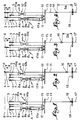
- Fig. 1 to 4 schematically illustrate all the elements of a mechanical armor with hooks according to the invention, respectively in the low, medium, intermediate and high position of the collar of the yoke.
- an armor mechanism capable of generating four positions of the warp threads of a weaving loom which comprises, for each yoke, two neighboring shedding devices A and B which are provided with two hooks 1, 2 and 3, 4 intended to cooperate with two claw frames 5 and 6 each carrying knives known per se and not shown.
- the hooks 1 and 2 of the first device A are connected by a cord 7 surrounding the first pulley 8 a of a block 8. Also the hooks 3, 4 of the second device B are connected by a cord 9 surrounding the first pulley 10 a d 'a mitt 10.
- Hooks 1, 2 and 3, 4 move vertically through knives arranged on the frame of claws 5 and 6 and driven back and forth.
- the muffle 8 of the device A comprises a third pulley 8 c mounted idle and of diameter smaller than that of the pulleys 8 a and 8 b .
- a cord 15 one end of which is anchored to a fixed point 13 a of the frame 13 successively surrounds the idler pulley 8 c of the block 8, the return pulley 11 secured to the frame 13, the second pulley 8 b of the block 8 of the first device A, the second deflection pulley 12 and finally the second pulley 10 b of the block 10 of the second device B.
- the other end of the cord 15 carries a snap hook or collar 16 to which at least one stringer 17 is fixed at the level of the hole plate 18.
- a double haulage is thus produced, making it possible to obtain four desired positions of the collar 16, that is to say a low position corresponding to the lower position of the warp threads (fig. 1), a second average position shown in fig. 2, a third intermediate position (fig. 3) and a fourth upper or upper position of the warp threads (fig. 4).
- claw frames 5 and 6 perform a back-and-forth movement equal to a distance referenced a .
- the second position of the carabiner or collar 16 is reached when the hooks 3 and 4 of the device B are raised alternately and respectively by the claw frames 5 and 6, while the hooks 1 and 2 of the first device A remain in the low position, c that is to say that they are not driven by the knives of said frames.
- the cord 15, one end of which is connected to a fixed point 13 has frame 13 is pulled by the pulley 10b from the block 10 of the second device B by a value which allows the carabiner or collar 16 to move a distance a equivalent to that of the claw frames 5 and 6 (fig. 2) .
- the third position of the carabiner or collar 16 is reached when the hooks 1 and 2 of the first device A are lifted alternately by the knives of the claw frames 5 and 6, while the hooks 3 and 4 remain in the low position, that is that is, they are not driven by said executives.
- the vertical movement of the block 8 successively drives the cord 15 around the second pulley 8 b of the block 8 of the first device A, the idler pulley 8 c , the two return pulleys 11 and 12, and finally the second pulley 10 b of the muffle 10 of the second device B.
- the displacement of the cord 15 generated by the back-and-forth movement of the hooks 1, 2 of the device A allows the carabiner or collar 16 to move a distance 2 a relative to the hole plate 18 (fig. 3).
- a shedding machine is thus obtained to reach four positions of the collar 16 relative to the plate holes 18 for the same displacement of the griffe frames 5 and 6, these four positions can be achieved following sequences freely programmed ( from a given position, one can directly reach any of the other three positions).
- the devices A and B can be those described in French patent 2,587,045 in the name of the Applicant.
Abstract
Description
La présente invention a trait à une mécanique d'armure permettant d'amener des fils de chaîne dans quatre positions différentes par l'intermédiaire de deux cadres de griffes mobiles verticalement.The present invention relates to an armor mechanism making it possible to bring warp yarns into four different positions by means of two claw frames movable vertically.
On sait qu'il existe des dispositifs qui permettent d'amener les fils de chaîne dans trois positions différentes par l'intermédiaire de plusieurs cadres de griffes mobiles verticalement. Cette mécanique d'armure comprend deux dispositifs voisins de formation de la foule qui comportent chacun deux crochets mobiles verticalement sous l'effet de couteaux qui se déplacent en opposition suivant un mouvement de va-et-vient Les crochets de chaque dispositif sont réunis par une cordelette passant autour d'une des poulies constituant le moufle. Entre la seconde poulie des moufles de chaque dispositif est placée une poulie montée folle sur un axe fixe par rapport au bâti de la mécanique, tandis qu'un cordon dont l'une des extrémités est ancrée dans le bâti entoure d'abord la seconde poulie du moufle du premier dispositif de formation de la foule, puis la poulie folle montée sur l'axe fixe et enfin la seconde poulie du moufle du second dispositif.We know that there are devices which allow the warp yarns to be brought into three different positions by means of several claw frames movable vertically. This armor mechanism includes two neighboring crowd-forming devices which each have two hooks movable vertically under the effect of knives which move in opposition in a back-and-forth movement. The hooks of each device are joined by a cord passing around one of the pulleys constituting the block. Between the second pulley of the mittens of each device is placed a pulley mounted idly on a fixed axis relative to the mechanical frame, while a cord whose one end is anchored in the frame first surrounds the second pulley of the muffle of the first crowd formation device, then the idler pulley mounted on the fixed axis and finally the second pulley of the muffle of the second device.
Cette mécanique d'armure permet donc de placer dans trois positions différentes le collet se trouvant à une extrémité libre du cordon et à laquelle est accrochée au moins une lisse.This armor mechanism therefore allows the collar located at one free end of the cord to which at least one stringer is attached to be placed in three different positions.
On connaît également et suivant le brevet européen 433 196 au nom de la présente Demanderesse des dispositifs de formation de la foule qui permettent d'assurer une ouverture importante de son pas. Ces dispositifs comprennent une poulie folle de diamètre réduit qui est montée dans le moufle connu en soi, tandis qu'une autre poulie de renvoi est prévue fixe sur le bâti de la mécanique. Un cordon est fixé par l'une de ses extrémités sur le bâti de la mécanique pour ensuite entourer successivement la poulie folle, la poulie de renvoi et enfin la seconde poulie du moufle du dispositif.Also known and according to European patent 433 196 in the name of the present Applicant crowd training devices which allow to ensure a significant opening of his step. These devices include an idler pulley of reduced diameter which is mounted in the block known per se, while another return pulley is provided fixed on the frame of the mechanics. A cord is fixed by one of its ends to the mechanical frame to then successively surround the idler pulley, the return pulley and finally the second pulley of the device's block.
Le dispositif de formation de la foule dont l'extrémité libre du cordon portant un collet auquel est attachée une lisse, permet soit de doubler la hauteur d'ouverture de la foule en maintenant la course des couteaux, soit de diminuer celle-ci de moitié en conservant la hauteur de foule originaire.The crowd formation device, the free end of the cord carrying a collar to which a beam is attached, makes it possible either to double the opening height of the crowd while maintaining the stroke of the knives, or to reduce it by half retaining the height of the original crowd.
Aucun des dispositifs décrits précédemment ne permet à une mécanique d'armure d'obtenir quatre positions des fils de chaîne.None of the devices described above allows a weave mechanic to obtain four positions of the warp threads.
C'est à cet inconvénient qu'entend plus particulièrement remédier l'invention.It is to this drawback that the invention more particularly intends to remedy.
La mécanique d'armure suivant la présente invention comprend une poulie folle montée à rotation dans le moufle du premier dispositif, deux poulies de renvoi tournant librement chacune autour d'un axe solidaire du bâti de la mécanique, et un cordon dont l'une des extrémités est ancrée au bâti de la mécanique et qui entoure succesivement la poulie folle solidaire du moufle du premier dispositif, la première poulie folle solidaire du bâti, la seconde poulie du moufle du premier dispositif, la seconde poulie folle solidaire du bâti, et la seconde poulie du moufle du second dispositif tandis que l'autre extrémité dudit cordon est associée à un collet auquel est accrochée au moins une lisse.The armor mechanics according to the present invention comprises a crazy pulley rotatably mounted in the block of the first device, two deflection pulleys each freely rotating about an axis secured to the frame of the mechanics, and a cord, one of the ends is anchored to the mechanical frame and which successively surrounds the idler pulley attached to the block of the first device, the idler pulley attached to the frame, the second idler pulley of the first device, the second idler pulley attached to the frame, and the second pulley of the muffle of the second device while the other end of said cord is associated with a collar to which at least one stringer is attached.
Le dessin annexé, donné à titre d'exemple, permettra de mieux comprendre l'invention, les caractéristiques qu'elle présente et les avantages qu'elle est susceptible de procurer :The appended drawing, given by way of example, will allow a better understanding of the invention, the characteristics which it presents and the advantages which it is capable of providing:
Fig. 1 à 4 illustrent schématiquement l'ensemble des éléments d'une mécanique d'armure à crochets suivant l'invention, respectivement en position basse, moyenne, intermédiaire et haute du collet de l'arcade.Fig. 1 to 4 schematically illustrate all the elements of a mechanical armor with hooks according to the invention, respectively in the low, medium, intermediate and high position of the collar of the yoke.
On a représenté en fig. 1 à 4 une mécanique d'armure propre à engendrer quatre positions des fils de chaînes d'un métier à tisser qui comprend pour chaque arcade deux dispositifs voisins de formation de la foule A et B qui sont pourvus respectivement de deux crochets 1, 2 et 3, 4 destinés à coopérer avec deux cadres de griffes 5 et 6 portant chacun des couteaux connus en soi et non représentés.There is shown in fig. 1 to 4 an armor mechanism capable of generating four positions of the warp threads of a weaving loom which comprises, for each yoke, two neighboring shedding devices A and B which are provided with two
Les crochets 1 et 2 du premier dispositif A sont reliés par un cordon 7 entourant la première poulie 8a d'un moufle 8. Egalement les crochets 3, 4 du second dispositif B sont reliés par un cordon 9 entourant la première poulie 10a d'un moufle 10.The
Les crochets 1, 2 et 3, 4 se déplacent verticalement par l'intermédiaire des couteaux disposés sur le cadre de griffes 5 et 6 et animés d'un mouvement de va-et-vient.
Le moufle 8 du dispositif A comporte une troisième poulie 8c montée folle et de diamètre inférieur à celui des poulies 8a et 8b.The
Entre les dispositifs A et B sont placées deux poulies de renvoi 11 et 12 tournant librement chacune autour d'un axe solidaire du bâti 13 de la mécanique. Un cordon 15 dont l'une des extrémités est ancrée à un point fixe 13a du bâti 13 entoure successivement la poulie folle 8c du moufle 8, la poulie de renvoi 11 solidaire du bâti 13, la seconde poulie 8b du moufle 8 du premier dispositif A, la seconde poulie de renvoi 12 et enfin la seconde poulie 10b du moufle 10 du second dispositif B. L'autre extrémité du cordon 15 porte un mousqueton ou collet 16 auquel au moins une lisse 17 est fixée au niveau de la plaque à trous 18.Between the devices A and B are placed two
On réalise ainsi un double mouflage permettant d'obtenir quatre positions recherchées du collet 16, c'est-à-dire une position basse correspondant à la position inférieure des fils de chaîne (fig. 1), une seconde position moyenne représentée en fig. 2, une troisième position intermédiaire (fig. 3) et une quatrième position haute ou supérieure des fils de chaîne (fig. 4).A double haulage is thus produced, making it possible to obtain four desired positions of the
Lorsque les fils de chaîne doivent être en position basse (fig. 1), les crochets 1, 2 et 3, 4 des dispositifs A et B ne sont pas entraînés par les couteaux des cadres de griffes 5 et 6 lorsque ces derniers effectuent un mouvement de va-et-vient. Ainsi, le collet 16 demeure en position basse au niveau de la planche à trous 18 et tous les crochets 1, 2 et 3, 4 du dispositif A et B se trouvent en position basse.When the warp threads must be in the low position (fig. 1), the
On note que les cadres de griffes 5 et 6 effectuent un mouvement de va-et-vient égal à une distance référencée a.Note that the
La seconde position du mousqueton ou collet 16 est atteinte lorsque les crochets 3 et 4 du dispositif B sont soulevés alternativement et respectivement par les cadres de griffes 5 et 6, tandis que les crochets 1 et 2 du premier dispositif A restent en position basse, c'est-à-dire qu'ils ne sont pas entraînés par les couteaux desdits cadres. En effet, le cordon 15 dont l'une des extrémités est reliée à un point fixe 13a du bâti 13 est tiré par la poulie 10b du moufle 10 du second dispositif B d'une valeur qui permet au mousqueton ou collet 16 de se déplacer d'une distance a équivalente à celle des cadres de griffes 5 et 6 (fig. 2).The second position of the carabiner or
La troisième position du mousqueton ou collet 16 est atteinte lorsque les crochets 1 et 2 du premier dispositif A sont soulevés alternativement par les couteaux des cadres de griffes 5 et 6, tandis que les crochets 3 et 4 restent en position basse, c'est-à-dire qu'ils ne sont pas entraînés par lesdits cadres. En effet, le déplacement vertical du moufle 8 entraîne successivement le cordon 15 autour de la seconde poulie 8b du moufle 8 du premier dispositif A, la poulie folle 8c, les deux poulies de renvoi 11 et 12, et enfin la seconde poulie 10b du moufle 10 du second dispositif B. Le déplacement du cordon 15 engendré par le mouvement de va-et-vient des crochets 1, 2 du dispositif A permet au mousqueton ou collet 16 de se déplacer d'une distance 2a par rapport à la plaque à trous 18 (fig. 3).The third position of the carabiner or
Enfin, la quatrième position du mousqueton ou collet 16 est atteinte lorsque les crochets 1, 3 et 2, 4 sont soulevés alternativement et respectivement par les couteaux des cadres de griffes 5 et 6 de manière que chaque moufle 8 et 10 des dispositifs A et B effectue un mouvement vertical de va-et-vient. On remarque que le cordon 15 est entraîné successivement autour des différentes poulies de la mécanique de manière que le collet 16 se déplace d'une distance 3a par rapport à la plaque à trous 18.Finally, the fourth position of the carabiner or
On obtient ainsi une mécanique d'armure permettant d'atteindre quatre positions du collet 16 par rapport à la plaque à trous 18 pour un même déplacement a des cadres de griffes 5 et 6, ces quatre positions peuvent être atteintes suivant des séquences programmées librement (d'une position donnée, on peut atteindre directement l'une quelconque des trois autres positions). Bien entendu, les dispositifs A et B peuvent être ceux décrits dans le brevet français 2 587 045 au nom de la Demanderesse.A shedding machine is thus obtained to reach four positions of the
Claims (1)
Applications Claiming Priority (2)
| Application Number | Priority Date | Filing Date | Title |
|---|---|---|---|
| FR9401179 | 1994-01-28 | ||
| FR9401179A FR2715666B1 (en) | 1994-01-28 | 1994-01-28 | Weave mechanics capable of generating four positions of warp threads in a loom. |
Publications (2)
| Publication Number | Publication Date |
|---|---|
| EP0665312A1 true EP0665312A1 (en) | 1995-08-02 |
| EP0665312B1 EP0665312B1 (en) | 1997-10-08 |
Family
ID=9459700
Family Applications (1)
| Application Number | Title | Priority Date | Filing Date |
|---|---|---|---|
| EP95420020A Expired - Lifetime EP0665312B1 (en) | 1994-01-28 | 1995-01-26 | Shedding mechanism providing four warp yarns positions in a loom |
Country Status (6)
| Country | Link |
|---|---|
| US (1) | US5540262A (en) |
| EP (1) | EP0665312B1 (en) |
| JP (1) | JP3390557B2 (en) |
| DE (1) | DE69500818T2 (en) |
| ES (1) | ES2109794T3 (en) |
| FR (1) | FR2715666B1 (en) |
Cited By (7)
| Publication number | Priority date | Publication date | Assignee | Title |
|---|---|---|---|---|
| GB2300650A (en) * | 1995-05-10 | 1996-11-13 | Michel Van De Wiele N V | Four-position jacquard machine |
| EP0884410A1 (en) * | 1997-06-12 | 1998-12-16 | N.V. Michel Van de Wiele | Four-Position open-shed jacquard machine. |
| EP0940489A1 (en) * | 1998-02-06 | 1999-09-08 | Kornblit Amnon | Tackle device for Jacquard machines |
| FR2910495A1 (en) * | 2006-12-26 | 2008-06-27 | Staubli Lyon Soc Par Actions S | Mounting mechanism for positioning warp thread of jacquard-type weaving machine, has hitch comprising fillet whose one end is fixed to frame of mechanism, while another end is arranged with lower cutter displacing lower pulley and cord |
| EP1975291A1 (en) | 2007-03-30 | 2008-10-01 | Staubli Faverges | Loom and method for weaving single cloth uncut velvet |
| CN101580993B (en) * | 2009-06-25 | 2011-07-20 | 杭州经纬自动化有限公司 | Electronic iacquard yarn selection device capable of forming three warp yarn positions |
| WO2019016773A1 (en) | 2017-07-20 | 2019-01-24 | Nv Michel Van De Wiele | Shed-forming device for a weaving machine |
Families Citing this family (4)
| Publication number | Priority date | Publication date | Assignee | Title |
|---|---|---|---|---|
| BE1008975A5 (en) * | 1994-12-20 | 1996-10-01 | Wiele Michel Van De Nv | Jacquard WITH rigging. |
| BE1015098A5 (en) * | 2002-09-09 | 2004-10-05 | Wiele Michel Van De Nv | Shed-forming device for a weaving machine. |
| FR2900666B1 (en) * | 2006-05-03 | 2008-06-20 | Staubli Lyon Soc Par Actions S | CROWN FORMING MECHANISM, WEAVING EQUIPPED WITH SUCH A MECHANISM AND METHOD OF SELECTING MOBILE HOOKS OF SUCH A MECHANISM |
| EP3165643B1 (en) * | 2015-11-04 | 2018-04-18 | NV Michel van de Wiele | Jacquard machine, face-to-face weaving machine comprising at least one jacquard machine, and method of setting up a jacquard machine |
Citations (5)
| Publication number | Priority date | Publication date | Assignee | Title |
|---|---|---|---|---|
| BE548296A (en) * | ||||
| BE546310A (en) * | ||||
| FR64421E (en) * | 1953-06-22 | 1955-11-10 | Lehembre & Cie A | Universal multi-position mechanics for looms |
| EP0433196A1 (en) * | 1989-12-15 | 1991-06-19 | Staubli-Verdol S.A. | Shed-forming device permitting an important opening of the shed |
| EP0570947A1 (en) * | 1992-05-19 | 1993-11-24 | N.V. Michel Van de Wiele | Tackle mechanism for a jacquard machine |
Family Cites Families (3)
| Publication number | Priority date | Publication date | Assignee | Title |
|---|---|---|---|---|
| FR433196A (en) * | 1911-08-12 | 1911-12-27 | Andre Julien Mahoudeau | Convex lift planes |
| FR2647473B1 (en) * | 1989-05-24 | 1991-07-26 | Staubli Verdol | IMPROVEMENTS ON THREE-POSITION ARMOR MECHANICS |
| BE1004347A3 (en) * | 1990-05-31 | 1992-11-03 | Wiele Michel Van De Nv | HOIST suspension for a Jacquard jacquard AND WITH SUCH SUSPENSION HOIST. |
-
1994
- 1994-01-28 FR FR9401179A patent/FR2715666B1/en not_active Expired - Fee Related
-
1995
- 1995-01-23 US US08/377,654 patent/US5540262A/en not_active Expired - Fee Related
- 1995-01-25 JP JP01013795A patent/JP3390557B2/en not_active Expired - Fee Related
- 1995-01-26 ES ES95420020T patent/ES2109794T3/en not_active Expired - Lifetime
- 1995-01-26 EP EP95420020A patent/EP0665312B1/en not_active Expired - Lifetime
- 1995-01-26 DE DE69500818T patent/DE69500818T2/en not_active Expired - Lifetime
Patent Citations (5)
| Publication number | Priority date | Publication date | Assignee | Title |
|---|---|---|---|---|
| BE548296A (en) * | ||||
| BE546310A (en) * | ||||
| FR64421E (en) * | 1953-06-22 | 1955-11-10 | Lehembre & Cie A | Universal multi-position mechanics for looms |
| EP0433196A1 (en) * | 1989-12-15 | 1991-06-19 | Staubli-Verdol S.A. | Shed-forming device permitting an important opening of the shed |
| EP0570947A1 (en) * | 1992-05-19 | 1993-11-24 | N.V. Michel Van de Wiele | Tackle mechanism for a jacquard machine |
Cited By (14)
| Publication number | Priority date | Publication date | Assignee | Title |
|---|---|---|---|---|
| GB2300650A (en) * | 1995-05-10 | 1996-11-13 | Michel Van De Wiele N V | Four-position jacquard machine |
| FR2734000A1 (en) * | 1995-05-10 | 1996-11-15 | Wiele Michel Van De Nv | JACQUARD JOB WITH FOUR POSITIONS |
| GB2300650B (en) * | 1995-05-10 | 1998-09-09 | Michel Van De Wiele N V | Four-position jacquard machine |
| EP0884410A1 (en) * | 1997-06-12 | 1998-12-16 | N.V. Michel Van de Wiele | Four-Position open-shed jacquard machine. |
| BE1011210A3 (en) * | 1997-06-12 | 1999-06-01 | Wiele Michel Van De Nv | FOUR TEETH OPEN GAAP jacquard. |
| EP0940489A1 (en) * | 1998-02-06 | 1999-09-08 | Kornblit Amnon | Tackle device for Jacquard machines |
| FR2910495A1 (en) * | 2006-12-26 | 2008-06-27 | Staubli Lyon Soc Par Actions S | Mounting mechanism for positioning warp thread of jacquard-type weaving machine, has hitch comprising fillet whose one end is fixed to frame of mechanism, while another end is arranged with lower cutter displacing lower pulley and cord |
| EP1939338A1 (en) | 2006-12-26 | 2008-07-02 | Staubli Lyon | Shed forming device in a Jacquard loom, and Jacquard loom equipped with such a device |
| EP1975291A1 (en) | 2007-03-30 | 2008-10-01 | Staubli Faverges | Loom and method for weaving single cloth uncut velvet |
| FR2914321A1 (en) * | 2007-03-30 | 2008-10-03 | Staubli Faverges Sca | WOVEN WEAVING AND METHOD OF Weaving VELVET SINGLE PINE |
| US7721768B2 (en) | 2007-03-30 | 2010-05-25 | Staubli Faverges | Loom and a method for weaving single-web loop velvet |
| CN101580993B (en) * | 2009-06-25 | 2011-07-20 | 杭州经纬自动化有限公司 | Electronic iacquard yarn selection device capable of forming three warp yarn positions |
| WO2019016773A1 (en) | 2017-07-20 | 2019-01-24 | Nv Michel Van De Wiele | Shed-forming device for a weaving machine |
| BE1025414B1 (en) * | 2017-07-20 | 2019-02-20 | Nv Michel Van De Wiele | GAAP FORMAT FOR A WEAVING MACHINE |
Also Published As
| Publication number | Publication date |
|---|---|
| DE69500818T2 (en) | 1998-04-02 |
| JPH0835144A (en) | 1996-02-06 |
| FR2715666A1 (en) | 1995-08-04 |
| ES2109794T3 (en) | 1998-01-16 |
| DE69500818D1 (en) | 1997-11-13 |
| FR2715666B1 (en) | 1996-05-03 |
| US5540262A (en) | 1996-07-30 |
| JP3390557B2 (en) | 2003-03-24 |
| EP0665312B1 (en) | 1997-10-08 |
Similar Documents
| Publication | Publication Date | Title |
|---|---|---|
| EP0399930B1 (en) | Improvements in jacquard looms with three positions | |
| EP0665312B1 (en) | Shedding mechanism providing four warp yarns positions in a loom | |
| EP0214075A1 (en) | Shedding mechanism for a loom | |
| FR2752246A1 (en) | METHOD AND DEVICE FOR SELECTING THE MOVABLE HOOKS OF A CROWD TRAINING MECHANISM AND JACQUARD TYPE Loom | |
| FR2757544A1 (en) | CROWN FORMING DEVICE, MOUNTING METHOD, AND JACQUARD-TYPE WEAVING MACHINE EQUIPPED WITH SUCH A DEVICE | |
| EP1939338B1 (en) | Shed forming device in a Jacquard loom, and Jacquard loom equipped with such a device | |
| EP0045758B1 (en) | Mechanical control for the shedding of warp ends of a loom and loom comprising such mechanical control | |
| FR2587046A1 (en) | Device for controlling the patterns in textile machines | |
| EP0556165A1 (en) | Single heald selection and control device | |
| FR2779158A1 (en) | METHOD AND WEAVING MATERIAL FOR WEAVING HAIR FABRIC | |
| BE1008087A3 (en) | Improvements loom. | |
| EP0433196B1 (en) | Shed-forming device permitting an important opening of the shed | |
| FR2728278A1 (en) | JACQUARD JOB WITH HOIST DEVICE | |
| EP0839937B1 (en) | Three-position shedding mechanism and jacquard loom with such a mechanism | |
| EP0619390B1 (en) | Jacquard mechanism with different lifts | |
| FR2535743A1 (en) | SMOOTH CONTROL SYSTEM FOR MOVING WAVY MILL WEAVING MACHINE | |
| EP0566506B1 (en) | Device for reciprocating the knives in heavy centre-shed dobbies | |
| EP0527095B1 (en) | Draw system to control the heddle frames of a negative dobby | |
| BE1004998A4 (en) | Mechanical jacquard double no window open for the looms for making pile fabrics. | |
| FR2714396A1 (en) | Weft selection device on a loom. | |
| EP0136244B1 (en) | Mechanism for the control of the knife boxes of dobbies | |
| FR2728279A1 (en) | HOIST DEVICE FOR A JACQUARD MACHINE | |
| FR2708003A1 (en) | Process for the production of a double pile fabric separable in the plane of the pile | |
| FR2734000A1 (en) | JACQUARD JOB WITH FOUR POSITIONS | |
| BE905884Q (en) | DEVICE FOR CONTROLLING WEAVING HANDLES. |
Legal Events
| Date | Code | Title | Description |
|---|---|---|---|
| PUAI | Public reference made under article 153(3) epc to a published international application that has entered the european phase |
Free format text: ORIGINAL CODE: 0009012 |
|
| AK | Designated contracting states |
Kind code of ref document: A1 Designated state(s): BE CH DE ES FR GB IT LI |
|
| 17P | Request for examination filed |
Effective date: 19950902 |
|
| 17Q | First examination report despatched |
Effective date: 19960705 |
|
| RAP1 | Party data changed (applicant data changed or rights of an application transferred) |
Owner name: STAUBLI LYON |
|
| GRAG | Despatch of communication of intention to grant |
Free format text: ORIGINAL CODE: EPIDOS AGRA |
|
| GRAH | Despatch of communication of intention to grant a patent |
Free format text: ORIGINAL CODE: EPIDOS IGRA |
|
| GRAH | Despatch of communication of intention to grant a patent |
Free format text: ORIGINAL CODE: EPIDOS IGRA |
|
| GRAA | (expected) grant |
Free format text: ORIGINAL CODE: 0009210 |
|
| AK | Designated contracting states |
Kind code of ref document: B1 Designated state(s): BE CH DE ES FR GB IT LI |
|
| REG | Reference to a national code |
Ref country code: CH Ref legal event code: EP |
|
| REF | Corresponds to: |
Ref document number: 69500818 Country of ref document: DE Date of ref document: 19971113 |
|
| ITF | It: translation for a ep patent filed |
Owner name: ING. ZINI MARANESI & C. S.R.L. |
|
| GBT | Gb: translation of ep patent filed (gb section 77(6)(a)/1977) |
Effective date: 19971211 |
|
| REG | Reference to a national code |
Ref country code: ES Ref legal event code: FG2A Ref document number: 2109794 Country of ref document: ES Kind code of ref document: T3 |
|
| PLBE | No opposition filed within time limit |
Free format text: ORIGINAL CODE: 0009261 |
|
| STAA | Information on the status of an ep patent application or granted ep patent |
Free format text: STATUS: NO OPPOSITION FILED WITHIN TIME LIMIT |
|
| 26N | No opposition filed | ||
| REG | Reference to a national code |
Ref country code: GB Ref legal event code: IF02 |
|
| PGFP | Annual fee paid to national office [announced via postgrant information from national office to epo] |
Ref country code: CH Payment date: 20040114 Year of fee payment: 10 |
|
| PGFP | Annual fee paid to national office [announced via postgrant information from national office to epo] |
Ref country code: ES Payment date: 20040119 Year of fee payment: 10 |
|
| PGFP | Annual fee paid to national office [announced via postgrant information from national office to epo] |
Ref country code: GB Payment date: 20040120 Year of fee payment: 10 |
|
| PG25 | Lapsed in a contracting state [announced via postgrant information from national office to epo] |
Ref country code: GB Free format text: LAPSE BECAUSE OF NON-PAYMENT OF DUE FEES Effective date: 20050126 |
|
| PG25 | Lapsed in a contracting state [announced via postgrant information from national office to epo] |
Ref country code: ES Free format text: LAPSE BECAUSE OF NON-PAYMENT OF DUE FEES Effective date: 20050127 |
|
| PG25 | Lapsed in a contracting state [announced via postgrant information from national office to epo] |
Ref country code: LI Free format text: LAPSE BECAUSE OF NON-PAYMENT OF DUE FEES Effective date: 20050131 Ref country code: CH Free format text: LAPSE BECAUSE OF NON-PAYMENT OF DUE FEES Effective date: 20050131 |
|
| GBPC | Gb: european patent ceased through non-payment of renewal fee |
Effective date: 20050126 |
|
| REG | Reference to a national code |
Ref country code: CH Ref legal event code: PL |
|
| REG | Reference to a national code |
Ref country code: ES Ref legal event code: FD2A Effective date: 20050127 |
|
| PGFP | Annual fee paid to national office [announced via postgrant information from national office to epo] |
Ref country code: FR Payment date: 20090116 Year of fee payment: 15 |
|
| REG | Reference to a national code |
Ref country code: FR Ref legal event code: ST Effective date: 20100930 |
|
| PG25 | Lapsed in a contracting state [announced via postgrant information from national office to epo] |
Ref country code: FR Free format text: LAPSE BECAUSE OF NON-PAYMENT OF DUE FEES Effective date: 20100201 |
|
| PGFP | Annual fee paid to national office [announced via postgrant information from national office to epo] |
Ref country code: IT Payment date: 20110120 Year of fee payment: 17 Ref country code: DE Payment date: 20110111 Year of fee payment: 17 |
|
| PG25 | Lapsed in a contracting state [announced via postgrant information from national office to epo] |
Ref country code: DE Free format text: LAPSE BECAUSE OF NON-PAYMENT OF DUE FEES Effective date: 20120801 |
|
| REG | Reference to a national code |
Ref country code: DE Ref legal event code: R119 Ref document number: 69500818 Country of ref document: DE Effective date: 20120801 |
|
| PG25 | Lapsed in a contracting state [announced via postgrant information from national office to epo] |
Ref country code: IT Free format text: LAPSE BECAUSE OF NON-PAYMENT OF DUE FEES Effective date: 20120126 |
|
| PGFP | Annual fee paid to national office [announced via postgrant information from national office to epo] |
Ref country code: BE Payment date: 20130130 Year of fee payment: 19 |
|
| BERE | Be: lapsed |
Owner name: *STAUBLI LYON Effective date: 20140131 |
|
| PG25 | Lapsed in a contracting state [announced via postgrant information from national office to epo] |
Ref country code: BE Free format text: LAPSE BECAUSE OF NON-PAYMENT OF DUE FEES Effective date: 20140131 |