EP0664441B1 - Inductive position sensor - Google Patents
Inductive position sensor Download PDFInfo
- Publication number
- EP0664441B1 EP0664441B1 EP95103691A EP95103691A EP0664441B1 EP 0664441 B1 EP0664441 B1 EP 0664441B1 EP 95103691 A EP95103691 A EP 95103691A EP 95103691 A EP95103691 A EP 95103691A EP 0664441 B1 EP0664441 B1 EP 0664441B1
- Authority
- EP
- European Patent Office
- Prior art keywords
- conductor
- magnetic flux
- surface elements
- position indicator
- indicator according
- Prior art date
- Legal status (The legal status is an assumption and is not a legal conclusion. Google has not performed a legal analysis and makes no representation as to the accuracy of the status listed.)
- Expired - Lifetime
Links
- 230000001939 inductive effect Effects 0.000 title claims description 14
- 230000005291 magnetic effect Effects 0.000 claims abstract description 73
- 230000004907 flux Effects 0.000 claims abstract description 71
- 238000005259 measurement Methods 0.000 claims abstract description 29
- 230000007423 decrease Effects 0.000 claims abstract description 5
- 239000004020 conductor Substances 0.000 claims description 127
- 238000006073 displacement reaction Methods 0.000 claims description 12
- 238000011156 evaluation Methods 0.000 claims description 6
- 239000003302 ferromagnetic material Substances 0.000 claims description 6
- 239000012141 concentrate Substances 0.000 claims 1
- 238000012544 monitoring process Methods 0.000 claims 1
- 239000013589 supplement Substances 0.000 claims 1
- 238000004804 winding Methods 0.000 abstract description 7
- 230000005294 ferromagnetic effect Effects 0.000 abstract description 2
- 230000005540 biological transmission Effects 0.000 abstract 2
- 230000005284 excitation Effects 0.000 description 22
- 230000000149 penetrating effect Effects 0.000 description 7
- 230000001419 dependent effect Effects 0.000 description 6
- 238000013461 design Methods 0.000 description 6
- 230000008901 benefit Effects 0.000 description 5
- 230000002093 peripheral effect Effects 0.000 description 5
- 239000000654 additive Substances 0.000 description 4
- 230000000996 additive effect Effects 0.000 description 4
- 230000008859 change Effects 0.000 description 4
- 238000010276 construction Methods 0.000 description 4
- 241001295925 Gegenes Species 0.000 description 3
- 230000015572 biosynthetic process Effects 0.000 description 3
- 230000000694 effects Effects 0.000 description 3
- 230000001965 increasing effect Effects 0.000 description 3
- 230000010354 integration Effects 0.000 description 3
- 238000013459 approach Methods 0.000 description 2
- 230000037007 arousal Effects 0.000 description 2
- 230000000295 complement effect Effects 0.000 description 2
- 230000006872 improvement Effects 0.000 description 2
- 238000004519 manufacturing process Methods 0.000 description 2
- RYGMFSIKBFXOCR-UHFFFAOYSA-N Copper Chemical compound [Cu] RYGMFSIKBFXOCR-UHFFFAOYSA-N 0.000 description 1
- 238000005452 bending Methods 0.000 description 1
- 229910052802 copper Inorganic materials 0.000 description 1
- 239000010949 copper Substances 0.000 description 1
- 239000011258 core-shell material Substances 0.000 description 1
- 230000003247 decreasing effect Effects 0.000 description 1
- 238000009826 distribution Methods 0.000 description 1
- 230000008030 elimination Effects 0.000 description 1
- 238000003379 elimination reaction Methods 0.000 description 1
- 238000005516 engineering process Methods 0.000 description 1
- 238000000605 extraction Methods 0.000 description 1
- 230000001976 improved effect Effects 0.000 description 1
- 239000000463 material Substances 0.000 description 1
- 238000000034 method Methods 0.000 description 1
- 230000004048 modification Effects 0.000 description 1
- 238000012986 modification Methods 0.000 description 1
- 230000008569 process Effects 0.000 description 1
- 230000001902 propagating effect Effects 0.000 description 1
- 230000000630 rising effect Effects 0.000 description 1
- 125000006850 spacer group Chemical group 0.000 description 1
- 238000003860 storage Methods 0.000 description 1
- 230000002277 temperature effect Effects 0.000 description 1
- 230000008719 thickening Effects 0.000 description 1
- 238000012549 training Methods 0.000 description 1
- 230000004304 visual acuity Effects 0.000 description 1
Images


Classifications
-
- G—PHYSICS
- G01—MEASURING; TESTING
- G01D—MEASURING NOT SPECIALLY ADAPTED FOR A SPECIFIC VARIABLE; ARRANGEMENTS FOR MEASURING TWO OR MORE VARIABLES NOT COVERED IN A SINGLE OTHER SUBCLASS; TARIFF METERING APPARATUS; MEASURING OR TESTING NOT OTHERWISE PROVIDED FOR
- G01D5/00—Mechanical means for transferring the output of a sensing member; Means for converting the output of a sensing member to another variable where the form or nature of the sensing member does not constrain the means for converting; Transducers not specially adapted for a specific variable
- G01D5/12—Mechanical means for transferring the output of a sensing member; Means for converting the output of a sensing member to another variable where the form or nature of the sensing member does not constrain the means for converting; Transducers not specially adapted for a specific variable using electric or magnetic means
- G01D5/14—Mechanical means for transferring the output of a sensing member; Means for converting the output of a sensing member to another variable where the form or nature of the sensing member does not constrain the means for converting; Transducers not specially adapted for a specific variable using electric or magnetic means influencing the magnitude of a current or voltage
- G01D5/20—Mechanical means for transferring the output of a sensing member; Means for converting the output of a sensing member to another variable where the form or nature of the sensing member does not constrain the means for converting; Transducers not specially adapted for a specific variable using electric or magnetic means influencing the magnitude of a current or voltage by varying inductance, e.g. by a movable armature
- G01D5/204—Mechanical means for transferring the output of a sensing member; Means for converting the output of a sensing member to another variable where the form or nature of the sensing member does not constrain the means for converting; Transducers not specially adapted for a specific variable using electric or magnetic means influencing the magnitude of a current or voltage by varying inductance, e.g. by a movable armature by influencing the mutual induction between two or more coils
- G01D5/2046—Mechanical means for transferring the output of a sensing member; Means for converting the output of a sensing member to another variable where the form or nature of the sensing member does not constrain the means for converting; Transducers not specially adapted for a specific variable using electric or magnetic means influencing the magnitude of a current or voltage by varying inductance, e.g. by a movable armature by influencing the mutual induction between two or more coils by a movable ferromagnetic element, e.g. a core
Definitions
- the invention relates to an inductive position transmitter described in the preamble of claim 1.
- Such positioners are used to generate an electrical signal to generate, with the help of a constant or intermittent Relative movement occurring between two Bodies can be monitored or tracked in such a way that information about the current position of one of the two bodies with respect of the other is available.
- An embodiment are linear encoders in which, for. B. the movement and / or current position of a machine slide, which can be moved relative to the machine frame is to be recorded and controlled with high precision. To do this, it is necessary to continuously obtain a signal even if the sled moves at high speed moved, information about the current position of the Sledge supplies.
- Another embodiment are encoders with whose help is the current angular position of a rotating Body, for example the rotor of an electric motor regarding the stator, or the angle of rotation between two bodies rotatable relative to one another, for example the Azimuth or vertical angle of a theodolite's telescope should be measured.
- the angular positions can be adjusted in a similar way or rotational speeds of motor vehicle wheels or the current angular position of a carburetor throttle valve measure up.
- a linear position transmitter of the type mentioned is the DE-PS 25 11 683 removable.
- the ferromagnetic flux guide device includes two rectangular, elongated, flat plates that go together are arranged in parallel so that they are between their flat sides include an air gap. On one of the two short sides of the rectangle are these panels by one web perpendicular to the plate planes connected so that there is a U-shaped longitudinal section.
- This Footbridge extends through an excitation coil using alternating current is fed to generate a magnetic flux the one closed in a ring across the air gap Path can follow, with an approximately homogeneous in the air gap Magnetic field is formed.
- This flow guide is one of the connected to each other while moving body with the other one designed as a printed circuit Measuring coil arrangement is coupled, the several, for example, has two surface elements, of which each is enclosed by its own measuring coil winding, which in the simplest case consists of a single turn between an AC signal is tapped from both of its open ends can be.
- the two surface elements in the form of right triangles and so in one level next to each other so that they become one Complement the elongated rectangle, the long sides of which are parallel to the direction of displacement of the gap walls of the river guiding device defined passage area.
- This passage area also has the shape of a rectangle, its expansion in the direction of displacement in comparison to the length of the maximum displacement distance is small and that perpendicular to the direction of displacement slightly larger than that of is the rectangle formed by the two triangular surface elements and constantly covers it.
- the ladder sections of the two Windings that form the hypotenuses of the two triangles run parallel and at a predetermined distance from each other obliquely to the direction of displacement of the passage surface so that when they are shifted, the part of the one that passes in the gap Magnetic flux that passes through the one surface element in the Dimension increases as the one penetrating the other surface element Part gets smaller and vice versa.
- the two measuring coil signals thus obtained are subtracted from each other after rectification, so that you have an approximately linear, symmetrical to zero potential and signal freed from part of the possible interference receives that to be monitored for the current position of the two Body is representative.
- the object of the invention is inductive To train positioners of the type mentioned at the beginning, that with the simplest possible structure and minimal Effort the immediate output signal of the encoder over as large a part of the range of motion as possible the greatest possible accuracy of the design characteristic curve follows.
- the invention provides the Claim 1 laid down features.
- the invention therefore set the goal of training inductive position transmitters in such a way that with the simplest possible structure, a maximum undisturbed and homogeneous penetrating the measuring coil arrangement Magnetic flux is achieved.
- a first essential step in this direction the measure detailed in EP 05 10 367 B1 represents that of the excitation coil generated magnetic flux at least two in a ring closed paths are offered, one of which is a measuring path serves, i.e. used to generate the measurement signal
- Useful magnetic flux conducts across the gap that the passage area defined and in its area the at least one Surface element of the measuring coil arrangement is positioned while at least one further path closed in a ring serves as a compensation route and as large a part of the remaining magnetic flux coming from the excitation coil leads that he at least one surface element on this no influence depending on movement or position can exercise.
- the at least two surface elements have a common edge piece over which the Passage area due to the movement to be monitored can move.
- the joint provided according to the invention Edge between the adjacent surface elements, that every field line that overlaps with one surface element leaves, necessarily in an overlap with the Neighbor surface element occurs and vice versa. Furthermore is achieved that the displacement range that are traversed until the one separating the two surface elements Edge after entering noticeable inhomogeneous field areas the homogeneous field area inside the gap or one practically field-free area reached outside of the gap absolute minimum is reduced. As a result of this there is a much improved approximation of the actual characteristic curve to the "construction characteristic".
- a magnetoelectric motion sensor is known from GB 2; 053,489 A, in which the measuring coil arrangement two each from a measuring coil turn has enclosed surface elements.
- the two measuring coil turns have a common conductor section, but they are parallel to each other switched so that there is only a corresponding enlargement of the gives the coil connections tapped current.
- a change in the waveform and thus a solution of what is called when arranging the above DE-PS-25 11 683 resulting non-linearity problems with this Arrangement not possible. This is due to the fact that there are no passage areas here in the sense of the present invention, which are therefore also cannot move over the common ladder section. The latter forms accordingly no "edge piece" in the sense of the invention.
- the common border between adjacent surface elements can also be achieved in that the two surface elements at least in this border area not exactly in the same But lie in the direction of the one penetrating the gap Magnetic flux seen with the smallest possible distance are arranged one behind the other so that they are together come to cover.
- this requires a somewhat more complex process Structure of the measuring coil arrangement; when executing the measuring coils as printed circuits, for example, one must be on both sides coated board can be used. It also has to ensure that the two consecutive conductor sections defining the common edge symmetrically to The gap height center lies around the influence of field inhomogeneities to an absolute minimum.
- the common edge piece of a ladder piece is formed, the two measuring coil windings, the enclose the two surface elements, is common.
- this common conductor piece is expedient to make this common conductor piece as vertical as possible to the direction of displacement of the passage surface to let and train as short as possible.
- You build the measuring coil arrangement as a printed circuit so receives a particularly simple circuit board design, because the two adjacent surface elements can be arranged on the same side of the board.
- the history the common conductor piece is through a single mask determined so that for the effectiveness of the effects caused by him Field division the accuracy no longer plays a role otherwise two for the production of double-sided printed Circuits required masks are positioned to each other ought to.
- a particularly simple design of a measuring coil arrangement two surface elements each surrounded by a measuring coil winding can be achieved in that two conductor sections, one of which is a surface element and the other of which other surface elements each delimited along an edge, which is approximately parallel to the direction of displacement of the passage surface runs against the surface element in question, on their both ends to form a ring-shaped closed conductor are interconnected.
- This ring-shaped closed conductor must then have an electrical resistance, that is not a short circuit. This is required to be none too high load on the signal source and cause the current limit in the closed conductor.
- the two output signals tapped by two measuring coils via three output connections be, of which the one common to the two measuring coils closed ladder.
- This arrangement is special advantageous for rotary encoders. It leads to a particularly high one Measurement accuracy when the ring-shaped closed conductor is arranged so that in any position against each other movable body through the area enclosed by it both the excitation coil and at least that Magnetic flux penetrating the compensation path. Thereby is the output signal of each of the two measuring coils Integration over the vast majority of that in the arrangement generated magnetic flux generated. In each of the both output signals also almost all disturbance variables in the same Recorded in such a way that it becomes apparent in the subsequent difference formation lift out. Incidentally, only allows a ring closed ladder that a single ladder bridge for division of the magnetic flux at measuring angles of 360 ° or more for the highest accuracy can be used.
- the measuring coil arrangement several, in the direction of movement surface elements arranged offset against each other, their output signals successively in the course of the movement to be monitored be evaluated or with a change in the course of the movement changing weighting used to form a measurement signal such a closed conductor offers the Advantage that it is common to all such measuring coil subsystems can be used and for these different subsystems only brought out in different places Has output connections.
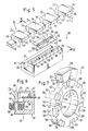
- the rotary encoder 1 shown in FIGS. 1 and 2 comprises a flow guiding device Made of ferromagnetic material a core 3 in the form of a pot and a yoke 4 is an excitation coil wound around a pin 5 of the core 3 6 (omitted in FIG. 1), and a carrier board 7, on one flat side two measuring coils 8, 9 in the form of printed Circuits are applied.
- the core 3 is a hollow circular cylinder with a cylinder wall 11, which is integrally connected to a bottom 12.
- the inside of the bottom 12 also extends in one piece molded pin 5, which is designed as a circular cylinder and is arranged concentrically to the cylinder wall 11, via a such a height that the distance between its in Figs. 1 and 2 above lying end face 15 of the through the end face 17 of the Cylinder wall 11 defined plane is slightly larger than the axial Thickness of the lower one described in more detail below
- the pin 5 and the bottom 12 are traversed by a central through bore 16, which can serve to accommodate a shaft, not shown.
- rib 20 On the end face 17 of the cylinder wall 11 is an annular, concentrically arranged in the figures projecting rib 20 is provided, approximately one has a square cross section and approximately in the middle between inner and outer peripheral edge of the end face 17th runs. At two points offset by 180 ° the rib 20 is pierced by two recesses 21 which extend to the end face 17.
- the carrier board 7 is designed in the form of a circular ring, the diameter of their central opening 23 being the same or slightly larger than the inside diameter and its outside diameter slightly smaller than the outside diameter of the cylinder wall 11 are. Furthermore, the carrier board 7 has two partially circular through openings 24, 24, are arranged concentrically so that they almost become one complement circular opening that only two on one opposite points through a narrow connecting bridge 25, 26 is interrupted. The openings 24, 24 and Connecting webs 25, 26 are arranged and dimensioned so that the carrier board 7 is placed on the end face 17 can be, the two parts of the rib 20 by the Extend openings 24 and the connecting webs 25 and 26 run in the recesses 21. That way it is Carrier board 7 non-rotatably connected to the core 3.
- the on the top in FIGS. 1 and 2 side of the carrier board 7 measuring coils 8, 9 comprise two circular, concentrically arranged conductors 30, 31, of which are the inside inside and the outside outside the openings 24, 24 is located.
- the inner conductor 30 is completely closed, while the outer conductor 31 has a small break, at the ends of which are approximately radial and two to each other parallel connecting leads 32, 33 are connected.
- Connecting web 26 Over the diametrically opposite Connecting web 26 extends radially extending connecting conductor 36, the conductor 30, 31 electrically conductive interconnects.
- the yoke 4 consists essentially of two semicircular Discs 40, 41, which have different radii and so are arranged so that they extend along the circle diameter The edges run directly next to each other in plan view and the two arcs are oriented away from each other In the axial direction, the disks 40, 41 are at a distance from one another arranged and by a semi-circular cylindrical connector 42 connected together.
- the radius of the semicircular disk 40 is slightly smaller than the inner radius of the cylinder wall 11, while the radius of the semi-cylindrical connector 42 corresponds to the radius of the pin 5.
- the one in the figures lower surface of the lower semicircular disk 40 is aligned with the lower end face of the connector 42, the upper face with the upper surface of the upper semicircular disc 41 lies in one plane.
- the yoke 4 is arranged so that the two holes 16, 44 are aligned and the lower one Semicircular disk 40 so inside the cylinder wall 11 of the core 3 is arranged that its upper surface in Fig. 2 with the Face 17 of the cylinder wall 11 is aligned.
- the radius of the upper semicircular disk 41 is equal to the outer radius the rib 20.
- the upper semicircular disk 41 On its lower side in FIGS. 1 and 2 the upper semicircular disk 41 has a protruding downward Rib 46, which extends over the entire circumference of the semicircular disk 41 extends and the same dimensions as the rib 20 has. In the assembled state, they lie behind bottom end face of the upper rib 46 and a corresponding large part of the upper end face of the lower rib 20 with a short distance away, so that these two end faces enclose a gap 47 between them, which in reality can be much smaller than in FIG Is shown for the sake of clarity.
- the air gap 43 between the cylindrical outer surface of the lower disc 40 and the Inner surface of the cylinder wall 11 is chosen so that by it gives the same magnetic resistance as through the gap 47.
- the air gap 45 between the underside of the disc 40 and the connector 42 on the one hand and the upper End face 15 of the pin 5, on the other hand, is as small as possible educated.
- the excitation coil 6 via connections, not shown supplied with an alternating voltage, it generates a magnetic one River that through the described formation of the core 3 and the yoke 4 two closed paths offered are formed geometrically different are, but essentially the same magnetic resistances exhibit.
- One of these two paths runs from that the pin 5 penetrating the excitation coil 6 via the gap 45 in the semi-cylindrical connector 42, through the upper semi-circular Disk 41, the rib 46, the gap 47, the rib 20, the cylinder wall 11 and over the bottom 12 back to the pin 5.
- the magnetic flux propagating along this measuring path penetrates always at least one of the two measuring coils 8, 9, in general but both measuring coils with different proportions, their respective size from the current position of the yoke 4 depends on the core 3.
- the other closed path extends from the spigot 5 over the gap 45, through the lower semicircular disc 40, via the gap 43 directly into the cylinder wall 11 and through the bottom 12 back to the pin 5.
- the magnetic flux in this compensation path closed in a ring always remains below the levels of the measuring coils 8, 9 and cannot enforce them.
- the difference in the two positions is the same Is zero, in which the yoke 4 is turned against the core 3 so that the lower end face of the rib 46 is half the part of the Rib 20 faces, which passes through the measuring coil 8 and to Half the part of the rib 20 which extends through the measuring coil 9.
- the passage area either completely over the measuring coil 8 or completely lies above the measuring coil 9, so that the entire gap 47 exceeding magnetic flux through one or the other of these two measuring coils goes, while the other of none magnetic flux is penetrated, has the difference signal a minimum or a maximum.
- the positions In between there is for everyone the positions a linear increase or decrease in which a Part of the magnetic flux passing through the gap 47 through the one of the two measuring coils 8, 9 and part by the other of these two measuring coils.
- the recesses 21 in the rib 20 can be put on the carrier board 7 filled with ferromagnetic material are so that the conductor pieces 34 and 36 almost uniform are surrounded by ferromagnetic material.
- the two measuring coils 8, 9 or the surface elements enclosed by them 38, 39 to be arranged in such a way that, where their boundary from the swept through the passage area defined by the gap 47 is, a common, here from the lead 34 or from Having connecting conductor 36 formed edge is obtained an extremely exact flow division. That means that every field line, due to a relative shift between the Core 3 and the yoke 4 no longer through the one of the two Measuring coils 8, 9 passes, necessarily through each other coil must pass through.
- the surface elements 38, 39 are significantly larger than the wall surfaces of the gap 47, each other opposite end faces of the ribs 20, 46 so that Radial inhomogeneities of the magnetic field hardly influence the measurement signals, since all of them are related to the Field lines contributing measurement signals always, in particular also when eccentricity or bearing play movements occur, within the surface areas enclosed by the measuring coils 8, 9 38, 39 are located. Radially further out Stray field components, which no longer apply, are like this weak that they are with regard to the accuracy of the measurement result and the characteristic curve is of no importance.
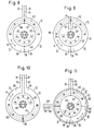
- the rotary encoder 50 shown in FIGS. 3 and 4 has one Flow guiding device consisting of two identical core shells 51, 51, and a carrier board 52, on the form of printed circuits both the excitation coil 53 and four measuring coils 54, 55, 56, 57 are attached.
- Each of the two core shells 51, 51 consists of two in one piece interconnected hollow half cylinders that are different Have radii and are arranged so that their cylinder axes and their running along the respective cylinder diameter Edges collapse, their outward curved Half-cylinder walls 58, 59 are oriented away from one another.
- On one end is through each of the two half cylinders completed a bottom wall 60, 61, the shape of which is exactly his corresponds to semi-cylindrical cross section.
- the two floor walls 60, 61 have the same axial thickness and go in one piece into each other.
- On the floor walls 60, 61 opposite The end of the half-cylinder walls 58, 59 have free End faces 62, 63, each of which is in the shape of a half Has circular ring.
- a centrally arranged, integrally connected pin 65 Extends from the bottom walls 60, 61 in the same direction as the half-cylinder walls 58, 59 a centrally arranged, integrally connected pin 65, whose axial height is greater than that of the half-cylinder walls 58, 59 is.
- the pin 65 is concentric Drilled hole 66, which again to accommodate a Shaft can serve.
- the two are Core shells 51 so firmly connected that the free End faces 67, 67 of the pins 65, 65 abut one another, wherein the bores 66, 66 are aligned and the End faces 62, 62 and 63, 63 of the half-cylinder walls 58, 58 or 59, 59 opposite each other, and between them Include columns 70, 71.
- the carrier board 52 is a circular disk with a central one Opening 68 formed, the diameter of which is somewhat larger than the outside diameter of the pins 65, 65.
- the outside diameter the circular disk 52 is slightly larger than that Diameter of the two larger half-cylinder walls 58, 58.
- the carrier board 52 is arranged in such a way that the two pins 65, 65 by their central Extend opening 68 and parallel to them Bottom walls 60, 61 of the core shells 51 runs, whereby they extends through the gaps 70, 71.
- the carrier board 52 has on its upper side in FIG. 3 the spiral-shaped excitation coil 53, which the central opening 68 immediately surrounds.
- the spiral-shaped excitation coil 53 instead of this as a printed one Circuit trained excitation coil can also be a Flat coil wound from wire attached in this area become.
- the four measuring coils 54 to 57 comprise four concentrically arranged circular conductors 72 to 75, two of which, namely the conductors 72 and 73 on the one hand and the conductors 74 and 75 on the other hand form an arrangement comprising two measuring coils, as has already been described with reference to FIG. 1.
- the only modification of the measuring coils 56, 57, the smaller Have diameters is that the outer Head 74 is completely closed while the inner conductor which has an interruption leading to the output connections.
- the output connections of these measuring coils 56, 57 not oriented radially outwards but radially inwards. The functional differences of such geometrically different ones Arrangements are described below with reference to the 8 to 11 explained in more detail.
- the dimensions of the measuring coils 54, 55 are chosen so that they in the assembled state from that in the gap 70 between the End faces 62, 62 are passed through magnetic flux can, while the measuring coils 56, 57 in the gap 71 between detect the magnetic flux passing through the end faces 63, 63.
- the carrier board 52 with one of the two body, not shown, whose rotational movement is monitored by measurement to be rotatably connected, while those from formed with two core shells 51, 51 flow guide arrangement the other of these two bodies is in a rotationally fixed connection.
- the magnetic flux generated by the exciting coil 53 will also here again two largely symmetrical, essentially the same magnetic resistance, closed in a ring Ways offered.
- One of these two paths extends through the two pins 65, 65 over the two Floor surfaces 60, 60 with the larger radius, through the cylinder walls 58, 58 and above that between these cylinder walls enclosed gap 70, the following magnetic flux the measuring coils 54, 55 can enforce.
- the output signals generated by the measuring coils 56, 57 can are used to measure signals with a larger amplitude to obtain. In the case of an encoder, however, this is only the case then makes sense when the accuracy of measurement is not very demanding be put.
- FIGS. 5 and 6 it is a linear encoder 85, which is analogous to the rotary encoder 1 and 2 is constructed. It includes a flow guide Made of ferromagnetic material there is a core 87 and a yoke 88, and one around one Leg 89 of the core wound excitation coil 90 (in FIG. 5 omitted) and one on one side of a carrier board 92 measuring coil arrangement in the form of a printed circuit, with two measuring coils 94, 95.
- a flow guide Made of ferromagnetic material there is a core 87 and a yoke 88, and one around one Leg 89 of the core wound excitation coil 90 (in FIG. 5 omitted) and one on one side of a carrier board 92 measuring coil arrangement in the form of a printed circuit, with two measuring coils 94, 95.
- the core 87 has the shape of an elongated, rectangular, hollow cuboid, whose upper wall 96 in FIGS. 5 and 6 about half cut away, so that in the figures left side wall of the hollow cuboid as a free leg 89 after protrudes above.
- the upper free end face 97 of the leg 89 lies somewhat lower than the inner surface of the one that has stopped Part of the top wall 96.
- the upper wall 96 On its outside, the upper wall 96 has one in the Figures protruding rib, parallel to the Longitudinal axis of the core 87 extends almost over its entire length and has an approximately square cross section. This rib is formed by three transverse recesses 98 interrupted, which extend to the surface of the wall 96 and so divide the rib into four partial ribs 99 of approximately the same length.
- the rectangular carrier board 92 has two continuous, elongated, rectangular openings 100 which are longitudinal aligned with each other and by a web 101 from each other are separated. Arrangement and dimensioning of these openings 100 is made so that the carrier board 92 on the top of the core 87 can be placed so that the two middle ribs 99, 99 through the two openings 100, 100 extend through, while the web 101 through the middle of the three recesses 98 runs.
- the two measuring coils have a rectangular, elongated one Conductor 103 on which the two openings 100 parallel to the edges of which almost completely surround. Only on one The conductor 103 is interrupted in the area of the web 101 and its two free ends are connected to output terminals 104, 105 connected, which are parallel to each other and perpendicular to Extend the longitudinal direction of the conductor 103 to the outside. Of the A connecting conductor extends on the opposite side of the conductor 103 106 via the web 101 between the output connections 104, 105 and parallel to these. This lead 106 forms the common edge of the two measuring coils 94, 95 enclosed surface areas 107, 108.
- the yoke 88 is designed as a rod, which comprises an elongated flat plate 110 into which recesses 112 are machined at regular intervals, in the area of which a protruding upward in FIGS. 5 and 6 Pinnacle 114 overhangs flat plate 110.
- the thickness of the flat plate 110 is the same as that of the remaining one Part of the top wall 96 of the core 87, and its width transverse to the longitudinal direction is slightly smaller than the width of the cut away Part of the top wall 96.
- the rectangular recesses 112 extend from one longitudinal edge of the flat Plate 110 into this and have such a depth that the remaining part of the flat plate the same thickness as has the free leg 89 of the core 87.
- the length of the recesses 112 is equal to the length of each of the four sub-ribs 99. Those that have remained between the recesses 112 Parts of the flat plate 110 are also of this length.
- the over the flat plate 110 in Figs. 5 and 6 upwards protruding crenellations 114 have an approximately L-shaped cross section with a vertically upwardly extending leg 115, the is arranged so that its left side in the figures aligned with the corresponding side surface of the flat plate 110.
- the vertical one Leg 115 into a horizontal leg 116, which in the points in the same direction as that between the recesses 112 stopped parts of the flat plate 110 to which it is attached extends approximately parallel.
- each of the horizontal legs 116 has a downward facing one Rib 117 extending the entire length of crenellation 114 extends and is therefore as long as each of the four ribs 99 of core 87.
- the yoke 88 When assembled, the yoke 88 is arranged so that the flat plate 110 roughly the place of the cut away Occupies part of the top wall 96 of the core 87, the horizontal Leg 116 to the remaining part of this upper wall 96 are directed.
- the yoke 88 is the same as in the figures right side of its flat plate 110 from the stopped Part of wall 96 through column 118 and from the face 97 of the leg 89 of the core 87 separated by a gap 119.
- the column 118 and the gap 119 are also real here much smaller than this in Fig. 6 for the sake of clarity is reproduced.
- the width with which the horizontal legs 116 of the battlements 114 protrude from the vertical legs 115 is dimensioned so that the core 87 facing in the assembled state free end face of the ribs 117 with a small distance 5 and 6 upper end faces of the parts of the rib 99 face each other.
- the columns 121 formed here are also smaller than shown in Fig. 6.
- the first type of path leads from leg 89 across the gap 119 in the upward leg 115, above the vertical Leg 116, the downward facing rib 117, over the gap 121 into one or two ribs 99, the one that has stopped Part of the top wall 96, as well as over the in the Figures right side wall and the bottom of the core 87 forming Hollow cuboid back to leg 89.
- the through this measurement path running magnetic flux penetrates the in the area of Column 121 arranged measuring coils 94, 95 in a position-dependent Way and thus generates the at the outputs of the two measuring coils tapped measurement signals, the difference for the current Position of the yoke 88 with respect to the core 87 is representative and also a linearly rising and falling triangular shape owns.
- the second type of closed path runs from Leg 89 over the gap 119 in the flat plate 110 and over column 118 immediately in the remaining part of the top wall 96, from where it goes back to the same way Leg 89 extends as above for the first type of ways has been described.
- the one running in these compensation paths Magnetic flux always remains below the level of the measuring coils 94, 95 and cannot influence the measuring signal in any way or distort. It symmetrically halves the total flow by more Switch off disturbance variables.
- the yoke 88 moves in the direction of the double arrow F against the core 87, so also move through the lower ones End faces of the ribs 117 defined passage areas over the surface elements enclosed by the measuring coils 94, 95 107, 108, so that the magnetic passing through the measuring coils River changed.
- the two outer partial ribs 99 are used on the in the longitudinal direction front and rear ends of the two measuring coils 94, To create 95 symmetrical and defined relationships.
- the on conductor sections of the measuring coils 94, 95 running at these ends, which, like the connecting conductor 106, extends through the recesses 99 can extend just like this completely or be largely embedded in ferromagnetic material, such as this has already been described above.
- the exemplary embodiment of a rotary encoder shown in FIG. 7 125 is comparatively accurate for the accurate measurement of one small angular range, for example 45 °, the repeated with a full 360 ° rotation (here eight times) is going through.
- the encoder 125 has one in cross-section E-shaped core 126 around its middle Leg 127 wound the excitation coil, not shown in Fig. 7 is.
- On the end face 122 one of the two outer E-legs 123, 124 is also not shown in FIG. 7 Measuring coil arrangement is provided, which largely corresponds to that in FIG. 5 corresponds to the measuring coil arrangement shown, i.e.
- the core 126 so also two in the longitudinal direction formed by approximately rectangular conductors of the core 126 comprises measuring coils arranged one behind the other, which also from the front of the relevant E-leg 123 or 124 of the core 126 provided rib parts can be.
- the main difference from the measuring coil arrangement Fig. 5 here is that the carrier board is not flat but as well as the end faces of the E-legs 123, 124, 127 of the Core 126 is curved in a circular arc in the longitudinal direction.
- a wheel is provided here as the yoke 128, which is around a dot-dash line Axis 130 rotatable in the direction of the double arrow R. is stored.
- the core 126 is at a short distance from
- the peripheral surface 129 of the yoke 128 is arranged so that its Extends longitudinally in the circumferential direction, i.e. its E-shaped Cross-section runs in the direction of the axis 130.
- the length of the core 126 circumferentially and the curvature of the yoke 128 facing end faces of the E-legs 123, 124, 127 chosen so that the core 126 approximately the angular range of 45 ° covered, which is to be resolved here by measurement.
- recesses 132 are machined from both end faces 131, which alternate starting from the peripheral surface 129 extend into the two end faces 131.
- Recesses lying on the same side and adjacent to one another 132 are each formed by a standing crenellated Part 134 separated. In the circumferential direction have the recesses 132 and the crenellated parts 134 the same length, which is chosen so that a recess 132 and a crenellated part 134 to be monitored Cover angle, here 45 °.
- the recesses 132 of one end face 131 are against the recesses 132 of the other end face 131 so offset arranged that seen in the axial direction always one Recess 132 and a crenellated part 134 are opposite.
- the depth of the recesses 132 is in the axial direction about twice the cross-sectional width of the two outer E-legs 123, 124 of the core 126.
- the axial width of the yoke 128 is chosen so that between the two sides machined recesses 132 a continuous Bridge remains, which has approximately the same width as the middle E-leg 127 of the core 126, which is approximately the has four times the width as the two outer E-legs 123, 124.
- the excitation coil generated magnetic flux two closed annular Ways offered, one of which is from the middle E-leg 127 via the E crossbar into one outer E leg 124, from this over that between the core 126 and the wheel-shaped Yoke 128 existing air gap in the opposite of the core 126 End faces of at least one and usually two crenellated parts 134 and of these over the middle Area of the peripheral surface 129 back into the middle E-leg 127 runs.
- the other way extends into in the same way through the other outer E-leg 123.
- the measuring coil arrangements of FIGS. 8 to 10 each include two measuring coils 8, 9, each of which consists of a single turn exists, which is designed so that that of the concerned Measuring coil enclosed surface element 38 or 39 in has approximately the shape of a half circular ring.
- the two half circular rings are arranged so that they are mutually to form a closed circular ring.
- Lines represent the areas through which the largely homogeneous magnetic flux passes when the relevant measuring coil arrangements in connection with a Flow guiding devices are used as they are related 3 and 4 has been described. There are this is the end face 67 of the pin 65 and the end faces 63 of the semi-cylindrical wall 59 (see Fig. 3) and the end face 62 of the semi-cylindrical wall 58.
- the flow guiding device formed by these core shells 51, 51 is against the measuring coil arrangements shown in FIGS. 8 to 10 each in the direction of the double arrow R, i.e. rotatable in the circumferential direction.
- the size and shape of the end faces 62 on the one hand and the two Surface elements 38, 39, and the mutual position of the the latter are matched to one another so that the one to be monitored Rotary movement in the direction of the respective double arrow R the end face 62 against the surface elements 38, 39 so that the magnetic flux passes through one of the two Surface elements 38, 39 increase to the same extent as the magnetic flux decreases by the other surface element and vice versa. So that two voltages in the measuring coils 8, 9 induced whose difference is the position of one of the two reproduces the body to be monitored with respect to the other.
- FIGS. 8 and 9 are two conductor sections 82, 83 and 84, 86, respectively one of which is the surface element 38 and the other of which Surface element 39 each along an edge that is approximately parallel to the direction of displacement of the end face 62 against that Surface element 8 to 9 runs, i.e. here along the inner (Fig. 8) or outer (Fig. 9) circumference limited, connected at their two ends so that they are one form annular closed conductors 82, 83 and 84, 86, respectively.
- This annularly closed conductors can e.g.
- radially running connecting conductor 34 is the closed conductor 82, 83 (Fig. 8) and 84, 86 (Fig. 9) with the output connections leading to the evaluation electronics connected.
- the other, the two surface elements 8, 9 on the outer Circumference (Fig. 8) or on the inner circumference (Fig. 9) delimiting conductor 72 or 73 is on the connecting conductor 36 diametrically opposite point interrupted and the free ends resulting from this are connected via connecting leads 32, 33, the radial parallel to the lead 34 at a short distance run outwards (FIG. 8) or radially inwards (FIG. 9), connected to the corresponding output connections.
- Each of the measuring coil arrangements of FIGS. 8 and 9 thus has three output connections, between which two measurement signals are tapped can be, the one with the middle lead 34 connected output connection as a common reference point serves. These signals are rectified and theirs Difference serves as a measure of the current position that the passage area defined by the end face 62 of the two surface elements 38, 39.
- the inner, closed conductor 82, 84 encloses the entire, within the face 67 through the plane of the drawing magnetic flux passing from bottom to top while he from that passing through the plane of the drawing in the opposite direction Magnetic flux encloses only the part that is inside the end face 63 extends.
- These two additional voltages are always the same size depending on the position. As long as one is representative of the current position Signal as mentioned above, only the difference between these two When using output signals, these two additional voltages fall out.
- the evaluation electronics within the inner conductor 73 to accommodate the measuring coil arrangement. With the inside Output connections connected, leading to the outside Otherwise wires must be carefully twisted together, so that they do not enclose any areas by the magnetic flux lines can step through.
- the connecting conductor 34 in the sense of the invention ideal edge conductor to make the two surface elements 38, 39 separates from each other so that it to both surface elements heard, it can be different from that shown in FIGS. 8 and 9, on the side of the connections, i.e. in Fig. 8 radially outside and in Fig. 9 radially within that of the passage surface swept area so that it covers the entire Interspace between the connecting conductors 32, 33 covered.
- these two embodiments are suitable for tracking rotary movements, that can cover an angle of less than 180 °.
- the advantage here is that it is from each of the two outer Connection conductor 32 or 33 a continuous conductor path to middle lead 34 in such a way that each of the electrical signals that can be tapped at these connecting conductors is generated by integration through the magnetic fluxes that are generated by pass through the area enclosed by this conductor path.
- this embodiment can, for example, the two connecting conductors 35, 35 'in two different levels so that they are in the areas in which they penetrate the drawing plane vertically Magnetic flux are exposed in the direction of this magnetic flux seen lying in a row and covering each other come. With a printed circuit this can happen again done by using the two sides of the board. Outside the area penetrated by a magnetic flux the two connecting conductors 35, 35 'are then brought apart be that their connecting contacts conveniently side by side Find space.
- two measuring coil systems according to Fig. 8 to use and arrange them rotated by 90 ° to each other.
- These two measuring coil systems have the inner, ring-shaped closed conductor 73 together. It is via two connecting conductors 36, 36 ', which are at an angle of 90 ° to each other are arranged offset with the two outer conductors 72, 72 'connected, which are actually the same diameter own and, for example, on the two flat sides double-sided printed circuit board for printed circuits could be.
- the vias required for this between the two sides of the board are in Fig. 11 of simplicity not reproduced for the sake of it.
- Each of the two outer conductors 72, 72 ' is on the diametrically opposite the associated connecting conductor 36, 36 ' Page broken and there like this above 8, with two connecting leads 32, 33 or spaced outwards 32 ', 33', between which there is an inner, completely closed conductor 73 incoming connecting conductor 34 or 34 'extends radially outwards.
- Each of the two measuring coil systems has three output connections, on which as explained above with reference to FIG.
- the signal difference at the output terminals 32, 33, 34 just then a particularly linear course if the signal difference at the connections 32 ', 33', 34 'the no longer ideally linear Triangle tips approximate and vice versa. So you can that the output signals, as mentioned above, with different Weighting combined, with the signal actually to be evaluated always the signal in particular strong, which is currently its ideal linear range passes through, while the other signal accordingly weighted less, a further improvement of the target optimal approximation of the actual characteristic curve the ideal characteristic curve given by the construction to reach.
- the middle connecting leads 34, 34 'to the connecting leads 32, 33 or 32 ', 33' opposite side of the board to lead and design there so broad that he the Spacer strips between the two associated other connection conductors completely covered.
Landscapes
- Physics & Mathematics (AREA)
- General Physics & Mathematics (AREA)
- Measurement Of Length, Angles, Or The Like Using Electric Or Magnetic Means (AREA)
- Transmission And Conversion Of Sensor Element Output (AREA)
- Radar Systems Or Details Thereof (AREA)
- Burglar Alarm Systems (AREA)
- Near-Field Transmission Systems (AREA)
- Switches That Are Operated By Magnetic Or Electric Fields (AREA)
- Investigating Or Analyzing Materials By The Use Of Magnetic Means (AREA)
Abstract
Description
Die Erfindung betrifft einen induktiven Stellungsgeber der im Oberbegriff des Anspruches 1 beschriebenen Art.The invention relates to an inductive position transmitter described in the preamble of claim 1.
Solche Stellungsgeber dienen dazu, ein elektrisches Signal zu erzeugen, mit dessen Hilfe eine ständige oder intermittierend auftretende Relativbewegung zwischen zwei Körpern so überwacht bzw. messend verfolgt werden kann, daß zu jedem beliebigen Zeitpunkt eine Information über die momentane Stellung des einen der beiden Körper bezüglich des anderen zur Verfügung steht.Such positioners are used to generate an electrical signal to generate, with the help of a constant or intermittent Relative movement occurring between two Bodies can be monitored or tracked in such a way that information about the current position of one of the two bodies with respect of the other is available.
Ein Ausführungsbeispiel sind Lineargeber, bei denen z. B. die Bewegung und/oder momentane Stellung eines Maschinenschlittens, der gegenüber dem Maschinenrahmen verschiebbar ist, mit hoher Präzision erfaßt und gesteuert werden soll. Dazu ist es erforderlich, ständig ein Signal zu gewinnen, das auch dann, wenn sich der Schlitten mit hoher Geschwindigkeit bewegt, Auskunft über die momentane Position des Schlittens liefert.An embodiment are linear encoders in which, for. B. the movement and / or current position of a machine slide, which can be moved relative to the machine frame is to be recorded and controlled with high precision. To do this, it is necessary to continuously obtain a signal even if the sled moves at high speed moved, information about the current position of the Sledge supplies.
Eine andere Ausführungsform stellen Drehgeber dar, mit deren Hilfe die momentane Winkellage eines rotierenden Körpers, beispielsweise des Rotors eines Elektromotors bezüglich des Stators, oder der Drehwinkel zwischen zwei gegeneinander verdrehbaren Körpern, beispielsweise der Azimut- oder Vertikalwinkel des Fernrohrs eines Theodoliten gemessen werden soll.Another embodiment are encoders with whose help is the current angular position of a rotating Body, for example the rotor of an electric motor regarding the stator, or the angle of rotation between two bodies rotatable relative to one another, for example the Azimuth or vertical angle of a theodolite's telescope should be measured.
In ähnlicher Weise lassen sich mit Drehgebern die Winkelstellungen bzw. Drehgeschwindigkeiten von Kraftfahrzeugrädern oder die momentane Winkelstellung einer Vergaser-Drosselklappe messen.The angular positions can be adjusted in a similar way or rotational speeds of motor vehicle wheels or the current angular position of a carburetor throttle valve measure up.
Ein linearer Stellungsgeber der eingangs genannten Art ist der DE-PS 25 11 683 entnehmbar. Bei diesem bekannten Geber umfaßt die ferromagnetische Fluß-Führungsvorrichtung zwei rechteckige, längliche, ebene Platten, die zueiander parallel so angeordnet sind, daß sie zwischen ihren Flachseiten einen Luftspalt einschließen. An einer der beiden kurzen Rechteckssseiten sind diese Platten durch einen senkrecht zu den Plattenebenen verlaufenden Steg so verbunden, daß sich ein U-förmiger Längsschnitt ergibt. Dieser Steg erstreckt sich durch eine Erregerspule, die mit Wechselstrom gespeist wird, um einen Magnetfluß zu erzeugen, der über den Luftspalt hinweg einem ringförmig geschlossenen Weg folgen kann, wobei im Luftspalt ein in etwa homogenes Magnetfeld ausgebildet wird.A linear position transmitter of the type mentioned is the DE-PS 25 11 683 removable. With this known encoder the ferromagnetic flux guide device includes two rectangular, elongated, flat plates that go together are arranged in parallel so that they are between their flat sides include an air gap. On one of the two short sides of the rectangle are these panels by one web perpendicular to the plate planes connected so that there is a U-shaped longitudinal section. This Footbridge extends through an excitation coil using alternating current is fed to generate a magnetic flux the one closed in a ring across the air gap Path can follow, with an approximately homogeneous in the air gap Magnetic field is formed.
Diese Fluß-Führungsvorrichtung ist mit dem einen der beiden gegeneinander bewegbaren Körper verbunden, während mit dem anderen eine als gedruckte Schaltung ausgebildete Meßspulenanordnung gekoppelt ist, die mehrere, beispielsweise zwei Flächenelemente aufweist, von denen jedes von einer eigenen Meßspulenwicklung umschlossen ist, die im einfachsten Fall aus einer einzigen Windung besteht, zwischen deren beiden offenen Enden ein Wechselspannungssignal abgegriffen werden kann. Bei einer in der obigen Druckschrift wiedergegebenen Ausführungsform sind die beiden Flächenelemente in Form von rechtwinkeligen Dreiecken ausgebildet und so in einer Ebene nebeneinander angeordnet, daß sie sich zu einem langgestreckten Rechteck ergänzen, dessen Längsseiten parallel zur Verschiebungsrichtung der von den Spaltwänden der Fluß-Führungsvorrichtung definierten Durchtrittsfläche verlaufen. Diese Durchtrittsfläche besitzt ebenfalls die Form eines Rechtecks, dessen Ausdehnung in Verschiebungsrichtung im Vergleich zur Länge der maximalen Verschiebungsweite klein ist und das senkrecht zur Verschiebungsrichtung etwas größer als das von den beiden dreieckigen Flächenelementen gebildete Rechteck ist und dieses ständig überdeckt. Die Leiterabschnitte der beiden Windungen, die die Hypotenusen der beiden Dreiecke bilden, verlaufen in einem vorgegebenen Abstand zueinander parallel und schräg zur Verschiebungsrichtung der Durchtrittsfläche so, daß bei deren Verschiebung der Teil des im Spalt übertretenden Magnetflusses, der das eine Flächenelement durchsetzt, in dem Maß zunimmt, wie der das andere Flächenelement durchsetzende Teil kleiner wird und umgekehrt. Die beiden so erhaltenen Meßspulensignale werden nach Gleichrichtung voneinander subtrahiert, so daß man ein in etwa lineares, zum Nullpotential symmetrisches und von einem Teil der möglichen Störeinflüsse befreites Signal erhält, das für die momentane Stellung der beiden zu überwachenden Körper repräsentativ ist.This flow guide is one of the connected to each other while moving body with the other one designed as a printed circuit Measuring coil arrangement is coupled, the several, for example, has two surface elements, of which each is enclosed by its own measuring coil winding, which in the simplest case consists of a single turn between an AC signal is tapped from both of its open ends can be. With one in the above publication reproduced embodiment are the two surface elements in the form of right triangles and so in one level next to each other so that they become one Complement the elongated rectangle, the long sides of which are parallel to the direction of displacement of the gap walls of the river guiding device defined passage area. This passage area also has the shape of a rectangle, its expansion in the direction of displacement in comparison to the length of the maximum displacement distance is small and that perpendicular to the direction of displacement slightly larger than that of is the rectangle formed by the two triangular surface elements and constantly covers it. The ladder sections of the two Windings that form the hypotenuses of the two triangles run parallel and at a predetermined distance from each other obliquely to the direction of displacement of the passage surface so that when they are shifted, the part of the one that passes in the gap Magnetic flux that passes through the one surface element in the Dimension increases as the one penetrating the other surface element Part gets smaller and vice versa. The two measuring coil signals thus obtained are subtracted from each other after rectification, so that you have an approximately linear, symmetrical to zero potential and signal freed from part of the possible interference receives that to be monitored for the current position of the two Body is representative.
Durch eine andere Ausgestaltung und Anordnung der Flächenelemente und/oder der Durchtrittsfläche lassen sich auch für ein solches Differenzsignal andere als lineare Verläufe vorgeben, wie dies oben für den allgemeinen Fall einer beliebigen Anzahl von Flächenelemente bereits erläutert wurde.By a different design and arrangement of the surface elements and / or the passage area can also be used for such a difference signal prescribe other than linear courses, like this above for the general case of any number of surface elements has already been explained.
Für alle diese Differenzsignale zeigt sich, daß ihr tatsächlicher Verlauf von dem durch die gewählte Konstruktion theoretisch vorgegebenen Verlauf, also beispielsweise von der angestrebten Linearität, zumindest in bestimmten Teilen des zu überwachenden Bewegungsbereiches abweicht und so die Meßgenauigkeit und/oder das Auflösungsvermögen in unerwünschter Weise begrenzt. For all these difference signals it turns out that you are more actual Course of that through the chosen construction theoretically predetermined course, for example of the desired Linearity, at least in certain parts of the thing to be monitored Movement range deviates and so the measuring accuracy and / or the resolving power is undesirably limited.
So endet der in der DE-PS 25 11 683 angestrebte lineare Verlauf der Ausgangssignal-Kennlinie bei Annäherung an die beiden Endlagen jeweils nicht in einer scharfen, sondern einer abgerundeten Spitze. Außerdem zeigt sich in der Praxis, daß die Kennlinie einer solchen Anordnung auch im Bereich des Nulldurchgangs nicht linear sondern S-förmig verzerrt verläuft. Zwar können diese Nichtliearitäten mit Hilfe der dem Geber nachgeschalteten Elektronik teilweise kompensiert werden. Dies erfordert jedoch einen zusätzlichen Aufwand und damit erhöhte Kosten.So ends the striven for in DE-PS 25 11 683 linear course of the output signal characteristic at Approach to the two end positions not in one sharp, but a rounded tip. Moreover shows in practice that the characteristic of such Arrangement not linear in the area of the zero crossing but S-shaped distorted. Although these non-linearities with the help of the electronics downstream of the encoder partially compensated. However, this requires an additional effort and thus increased costs.
Demgegenüber liegt der Erfindung die Aufgabe zugrunde, induktive Stellungsgeber der eingangs genannten Art so weiterzubilden, daß bei möglichst einfachem Aufbau und geringem Aufwand das unmittelbare Ausgangssignal des Gebers über einen möglichst großen Teil des Bewegungsbereiches mit möglichst großer Genauigkeit dem Konstruktions-Kennlinienverlauf folgt.In contrast, the object of the invention is inductive To train positioners of the type mentioned at the beginning, that with the simplest possible structure and minimal Effort the immediate output signal of the encoder over as large a part of the range of motion as possible the greatest possible accuracy of the design characteristic curve follows.
Zu Lösung dieser Aufgabe sieht die Erfindung die im Anspruch 1 niedergelegten Merkmale vor.To solve this problem, the invention provides the Claim 1 laid down features.
Diesen erfindungsgemäßen Maßnahmen liegt die Erkenntnis zugrunde, daß ein Teil der Schwierigkeiten, die sich beim Stand der Technik hinsichtlich der Meßgenauigkeit und des Auflösungsvermögens ergeben, weil die tatsächlich erzielte Ausgangssignal-Kennlinie vom theoretisch vorgegebenen Verlauf abweicht, darauf zurückzuführen ist, daß sowohl Streuanteile des von der Erregerspule erzeugten Magnetflusses als auch Feldinhomogenitäten insbesondere in den Randbereichen der Durchtrittsfläche auf die Meßspulenanordnung in Abhängigkeit von der zu überwachenden Bewegung veränderlich einwirken.These measures according to the invention are based on the knowledge that that part of the difficulties encountered in the stand the technology in terms of measurement accuracy and resolution result because the output signal characteristic actually achieved from the theoretically predetermined course deviates, is due to the fact that both stray portions of the magnetic flux generated by the excitation coil as well Field inhomogeneities in particular in the marginal areas of the Passage area on the measuring coil arrangement depending of the movement to be monitored.
Um diese Störungen zu vermindern, hat es sich die Erfindung daher zum Ziel gesetzt, induktive Stellungsgeber so auszubilden, daß bei möglichst einfachem Aufbau ein maximaler, ungestörter und homogner die Meßspulenanordnung durchsetzender Magnetfluß erzielt wird.In order to reduce these disturbances, it has the invention therefore set the goal of training inductive position transmitters in such a way that with the simplest possible structure, a maximum undisturbed and homogeneous penetrating the measuring coil arrangement Magnetic flux is achieved.
Einen ersten wesentlichen Schritt in dieser Richtung stellt die in EP 05 10 367 B1 ausführlich erläuterte Maßnahme dar, daß dem von der Erregerspule erzeugten Magnetfluß wenigstens zwei ringförmig geschlossene Wege angeboten werden, von denen einer als Meßweg dient, d.h. den zur Erzeugung des Meßsignals verwendeten Nutz-Magnetfluß über den Spalt leitet, der die Durchtrittsfläche definiert und in dessen Bereich das wenigstens eine Flächenelement der Meßspulenanordnung positioniert ist, während wenigstens ein weiterer ringförmig geschlossener Weg als Ausgleichsweg dient und einen möglichst großen Teil des übrigen von der Erregerspule kommenden Magnetflusses so führt, daß er auf dieses wenigstens eine Flächenelement zumindest keinen bewegungs- bzw. stellungsabhängigen Einfluß ausüben kann. A first essential step in this direction the measure detailed in EP 05 10 367 B1 represents that of the excitation coil generated magnetic flux at least two in a ring closed paths are offered, one of which is a measuring path serves, i.e. used to generate the measurement signal Useful magnetic flux conducts across the gap that the passage area defined and in its area the at least one Surface element of the measuring coil arrangement is positioned while at least one further path closed in a ring serves as a compensation route and as large a part of the remaining magnetic flux coming from the excitation coil leads that he at least one surface element on this no influence depending on movement or position can exercise.
Um zu einer weiteren Verbesserung zu kommen, d.h. einen noch größeren ungestörten, homogenen Nutzfluß zu erzielen, ist gemäß der Erfindung vorgesehen, daß die wenigstens zwei Flächenelemente ein gemeinsames Randstück aufweisen, über das sich die Durchtrittsfläche aufgrund der zu überwachenden Bewegung hinweg verschieben kann.To come to a further improvement, i.e. one to achieve even greater undisturbed, homogeneous useful flow provided according to the invention that the at least two surface elements have a common edge piece over which the Passage area due to the movement to be monitored can move.
Dieser Maßnahme liegt folgende Erkenntnis zugrunde: Verwendet man, wie dies beim Stand der Technik der Fall ist, zur Trennung von zwei einander benachbarten Flächenelementen zwei nebeneinanderliegende, in Verschiebungsrichtung der Durchtrittsfläche einen Abstand aufweisende Randstücke, die jeweils von einem Leiterstück der zugehörigen Meßspulenwicklung definiert werden, so bleibt zwischen diesen Rändern immer ein Flächenbereich, der weder zu dem einen noch zu dem anderen Flächenelement gehört. Der magnetische Fluß, der diesen Flächenbereich durchsetzt, während sich die Durchtrittsfläche über die beiden Flächenelemente verschiebt, trägt zur Erzeugung eines Meßsignals weder in der das eine Flächenelement umschließenden Meßspule noch in der das andere Flächenelement umschließenden Meßspule bei. Das führt dann, wenn der Einfluß von Störfeldern durch die Differenzbildung nicht völlig eliminiert werden kann zu einem Fehler dessen relative Größe um so größer ist, je größer das Verhältnis des ungenutzten Flächenbereichs zur genutzten Durchtrittsfläche ist.This measure is based on the following knowledge: If, as is the case with the prior art, for separating two adjacent surface elements two side by side, in the direction of displacement of the passage surface spaced edge pieces, each defined by a conductor piece of the associated measuring coil winding there is always a surface area between these edges, that neither to the one nor to the other surface element heard. The magnetic flux covering this area interspersed, while the passage area over the two Moves surface elements, contributes to the generation of a measurement signal neither in the measuring coil surrounding a surface element still in the measuring coil surrounding the other surface element at. This leads when the influence of interference fields by the Difference formation cannot be completely eliminated from one Error whose relative size is larger the larger that Ratio of the unused area to the used passage area is.
Darüber hinaus hat der zwischen den Flächenelementen liegende Flächenbereich zur Folge, daß an die beiden im Abstand zueinander verlaufenden Rand-Leiter sehr hohe Parallelitätsanforderungen gestellt werden müssen. Ändert sich nämlich der Abstand dieser beiden Leiter über ihre Länge hinweg entweder in ständig zu- bzw. abnehmender oder in alternierender Weise, so ist auch der zwischen den von Meßspulenwicklungen umschlossenen Flächenelementen verloren gehende Anteil des magnetischen Flusses im Spalt stellungsabhängig. Der verbleibende, die eine oder die andere Meßspule durchsetzende magnetische Fluß erhält damit eine zusätzliche stellungsabhängige Komponente, die zu einer Abweichung zwischen dem praktischen und dem theoretischen Verlauf der Ausgangskennlinie führt.In addition, the one lying between the surface elements Surface area as a result that the two at a distance from each other trending edge ladder very high parallelism requirements must be asked. This is because the distance changes of these two conductors along their length either in constantly increasing or decreasing or alternating, so is also between the surface elements enclosed by measuring coil windings lost part of the magnetic flux position-dependent in the gap. The remaining, the one or the magnetic flux penetrating another measuring coil thus receives a additional position-dependent component that leads to a deviation between the practical and the theoretical course the output characteristic leads.
Ein weiteres Problem ergibt sich beim Stand der Technik aus den an den Rändern des Spaltes bzw. der von ihm definierten Durchtrittsfläche immer und in unvermeidlicher Weise vorhandenen Feldinhomogenitäten. Nähert sich ein solcher Rand an die Grenzzone einander benachbarter Flächenelemente an, so verlassen beim Stand der Technik Feldbereiche die Überdeckung mit dem einen Flächenelement, die eine höhere Magnetflußdichte besitzen, als die gleichzeitig in eine Überdeckung mit dem benachbarten Flächenelement eintretenden Feldbereiche und umgekehrt, was erhebliche Fehler nach sich zieht.Another problem arises in the prior art at the edges of the gap or the one defined by it Passage area always and inevitably available Field inhomogeneities. Such an edge approaches the Border zone of adjacent surface elements, so leave in the prior art field areas with the overlap the one surface element, which have a higher magnetic flux density, than the one in overlap with the neighboring one Field areas entering the area element and vice versa, which results in significant errors.
Demgegenüber stellt der erfindungsgemäß vorgesehene gemeinsame Rand zwischen den einander benachbarten Flächenelementen sicher, daß jede Feldlinie, die die Überdeckung mit dem einen Flächenelement verläßt, notwendigerweise in eine Überdeckung mit dem Nachbar-Flächenelement eintritt und umgekehrt. Darüber hinaus wird erreicht, daß die Verschiebungsweite, die durchlaufen werden muß, bis der die beiden Flächenelemente voneinander trennende Rand nach seinem Eintreten in merkbare inhomogene Feldbereiche den homogenen Feldbereich im Spaltinneren bzw. einen praktisch feldfreien Bereich außerhalb des Spaltes erreicht, auf absolutes Minimum reduziert wird. Als Ergebnis hiervon ergibt sich eine stark verbesserte Annäherung des tatsächlichen Kennlinienverlaufes an die "Konstruktionskennlinie". In contrast, the joint provided according to the invention Edge between the adjacent surface elements, that every field line that overlaps with one surface element leaves, necessarily in an overlap with the Neighbor surface element occurs and vice versa. Furthermore is achieved that the displacement range that are traversed until the one separating the two surface elements Edge after entering noticeable inhomogeneous field areas the homogeneous field area inside the gap or one practically field-free area reached outside of the gap absolute minimum is reduced. As a result of this there is a much improved approximation of the actual characteristic curve to the "construction characteristic".
Zwar ist aus der GB 2;053,489 A ein magnetoelektrischer Bewegungssensor bekannt, bei dem die Meßspulenanordnung zwei jeweils von einer Meßspulenwindung umschlossene Flächenelemente aufweist. Die beiden Meßspulenwindungen besitzen zwar ein gemeinsames Leiterstück, doch sind sie zueinander parallel geschaltet, so daß sich lediglich eine entsprechende Vergrößerung des an den Spulenanschlüssen abgreifbaren Stroms ergibt. Eine Veränderung der Signalform und damit eine Lösung der sich bei der Anordnung der eingangs genannnten DE-PS-25 11 683 ergebenden Nichtlinearitätsprobleme ist mit dieser Anordnung jedoch nicht möglich. Dies beruht darauf, daß hier keine Durchtrittsflächen im Sinne der vorliegenden Erfindung vorhanden sind, die sich somit auch nicht über das gemeinsame Leiterstück verschieben können. Letzteres bildet demgemäß kein "Randstück" im Sinne der Erfindung. A magnetoelectric motion sensor is known from GB 2; 053,489 A, in which the measuring coil arrangement two each from a measuring coil turn has enclosed surface elements. The two measuring coil turns have a common conductor section, but they are parallel to each other switched so that there is only a corresponding enlargement of the gives the coil connections tapped current. A change in the waveform and thus a solution of what is called when arranging the above DE-PS-25 11 683 resulting non-linearity problems with this Arrangement not possible. This is due to the fact that there are no passage areas here in the sense of the present invention, which are therefore also cannot move over the common ladder section. The latter forms accordingly no "edge piece" in the sense of the invention.
Der gemeinsame Rand zwischen einander benachbarten Flächenelementen läßt sich auch dadurch erzielen, daß die beiden Flächenelemente zumindest in diesem Randbereich nicht exakt in der gleichen Fläche liegen sondern, in Richtung des den Spalt durchsetzenden Magnetflusses gesehen, mit einem möglichst kleinen Abstand hintereinander so angeordnet sind, daß sie miteinander zur Deckung kommen. Dies bedingt aber einen etwas aufwendigeren Aufbau der Meßspulenanordnung; bei einer Ausführung der Meßspulen als gedruckte Schaltungen muß beispielsweise eine beidseitig beschichtete Platine verwendet werden. Außerdem muß dafür gesorgt werden, daß die beiden hintereinander liegenden, den gemeinsamen Rand definierenden Leiterstücke symmetrisch zur Spalthöhenmitte liegen, um den Einfluß von Feldinhomogenitäten auf ein absolutes Minimum zu reduzieren.The common border between adjacent surface elements can also be achieved in that the two surface elements at least in this border area not exactly in the same But lie in the direction of the one penetrating the gap Magnetic flux seen with the smallest possible distance are arranged one behind the other so that they are together come to cover. However, this requires a somewhat more complex process Structure of the measuring coil arrangement; when executing the measuring coils as printed circuits, for example, one must be on both sides coated board can be used. It also has to ensure that the two consecutive conductor sections defining the common edge symmetrically to The gap height center lies around the influence of field inhomogeneities to an absolute minimum.
Um diesen Aufwand, zu dem auch noch die genaue Positionierung der beiden hintereinander anzuordnenden Leiter kommt, zu vermeiden, ist daher bei einer besonders bevorzugten Ausführungsform vorgesehen, daß das gemeinsame Randstück von einem Leiterstück gebildet wird, das den beiden Meßspulenwicklungen, die die beiden Flächenelemente umschließen, gemeinsam ist. Außerdem ist es zweckmäßig, dieses gemeinsame Leiterstück möglichst senkrecht zur Verschiebungsrichtung der Durchtrittsfläche verlaufen zu lassen und so kurz wie irgend möglich auszubilden. Baut man die Meßspulenanordnung als gedruckte Schaltung auf, so erhält man auf diese Weise eine besonders einfache Platinengestaltung, da die beiden einander benachbarten Flächenelemente auf der gleichen Platinenseite angeordnet werden können. Der Verlauf des gemeinsamen Leiterstücks ist durch eine einzige Maske bestimmt, so daß für die Effektivität der von ihm bewirkten Feldteilung die Genauigkeit keine Rolle mehr spielt, mit der ansonsten zwei zur Herstellung von doppelseitigen gedruckten Schaltungen benötigte Masken zueinander positioniert werden müßten.To this effort, in addition to the exact positioning of the two conductors to be arranged one behind the other is therefore in a particularly preferred embodiment provided that the common edge piece of a ladder piece is formed, the two measuring coil windings, the enclose the two surface elements, is common. Moreover it is expedient to make this common conductor piece as vertical as possible to the direction of displacement of the passage surface to let and train as short as possible. You build the measuring coil arrangement as a printed circuit, so receives a particularly simple circuit board design, because the two adjacent surface elements can be arranged on the same side of the board. The history the common conductor piece is through a single mask determined so that for the effectiveness of the effects caused by him Field division the accuracy no longer plays a role otherwise two for the production of double-sided printed Circuits required masks are positioned to each other ought to.
Eine besonders einfache Gestaltung einer Meßspulenanordnung mit zwei jeweils von einer Meßspulenwindung umschlossenen Flächenelementen läßt sich dadurch erzielen, daß zwei Leiterabschnitte, von denen der eine das eine Flächenelement und der andere das andere Flächenelement jeweils längs eines Randes begrenzt, der in etwa parallel zur Verschiebungsrichtung der Durchtrittsfläche gegen das betreffende Flächenelement verläuft, an ihren beiden Enden zur Bildung eines ringförmig geschlossenen Leiters miteinander verbunden sind. Dieser ringförmig geschlossene Leiter muß dann allerdings einen elektrischen Widerstand aufweisen, der keinen Kurzschluß darstellt. Dies ist erforderlich, um keine zu hohe Belastung der Signalquelle zu verursachen und den Strom in dem geschlossenen Leiter zu begrenzen.A particularly simple design of a measuring coil arrangement two surface elements each surrounded by a measuring coil winding can be achieved in that two conductor sections, one of which is a surface element and the other of which other surface elements each delimited along an edge, which is approximately parallel to the direction of displacement of the passage surface runs against the surface element in question, on their both ends to form a ring-shaped closed conductor are interconnected. This ring-shaped closed conductor must then have an electrical resistance, that is not a short circuit. This is required to be none too high load on the signal source and cause the current limit in the closed conductor.
Mit einer solchen Anordnung können die beiden Ausgangssignale von zwei Meßspulen über drei Ausgangsanschlüsse abgegriffen werden, von denen der eine zu dem beiden Meßspulen gemeinsamen geschlossenen Leiter führt. Diese Anordnung ist insbesondere bei Drehgebern vorteilhaft. Sie führt zu einer besonders hohen Meßgenauigkeit, wenn der ringförmig geschlossene Leiter so angeordnet ist, daß in jeder beliebigen Stellung der gegeneinander bewegbaren Körper durch die von ihm umschlossene Fläche sowohl der die Erregerspule als zumindest auch der den Ausgleichsweg durchsetzende Magnetfluß hindurchtritt. Dadurch wird das Ausgangssignal einer jeden der beiden Meßspulen durch Integration über den weitaus größten Teil des in der Anordnung auftretenden Magnetflusses erzeugt. Dabei werden in jedem der beiden Ausgangssignale auch nahezu alle Störgrößen in gleicher Weise erfaßt, sodaß sie sich bei der nachfolgenden Differenzbildung herausheben. Im Übrigen ermöglicht nur ein ringförmig geschlossener Leiter, daß ein einziger Leitersteg zur Aufteilung des Magnetflusses bei Meßwinkeln von 360° oder mehr für die Erzielung höchster Genauigkeit verwendet werden kann.With such an arrangement, the two output signals tapped by two measuring coils via three output connections be, of which the one common to the two measuring coils closed ladder. This arrangement is special advantageous for rotary encoders. It leads to a particularly high one Measurement accuracy when the ring-shaped closed conductor is arranged so that in any position against each other movable body through the area enclosed by it both the excitation coil and at least that Magnetic flux penetrating the compensation path. Thereby is the output signal of each of the two measuring coils Integration over the vast majority of that in the arrangement generated magnetic flux generated. In each of the both output signals also almost all disturbance variables in the same Recorded in such a way that it becomes apparent in the subsequent difference formation lift out. Incidentally, only allows a ring closed ladder that a single ladder bridge for division of the magnetic flux at measuring angles of 360 ° or more for the highest accuracy can be used.
Umfaßt nämlich, wie dies bei bestimmten Anwendungsfällen sinnvoll ist, die Meßspulenanordnung mehrere, in Bewegungsrichtung gegeneinander versetzt angeordnete Flächenelemente, deren Ausgangssignale im Verlauf der zu überwachenden Bewegung nacheinander ausgewertet werden oder mit einer sich im Verlauf der Bewegung ändernden Gewichtung zur Bildung eines Meßsignals herangezogen werden, so bietet ein solcher geschlossener Leiter den Vorteil, daß er für alle derartige Meßspulen-Untersysteme gemeinsam verwendet werden kann und für diese verschiedenen Untersysteme lediglich an verschiedenen Stellen herausgeführte Ausgangsanschlüsse aufweist.This includes how this makes sense in certain applications is, the measuring coil arrangement several, in the direction of movement surface elements arranged offset against each other, their output signals successively in the course of the movement to be monitored be evaluated or with a change in the course of the movement changing weighting used to form a measurement signal such a closed conductor offers the Advantage that it is common to all such measuring coil subsystems can be used and for these different subsystems only brought out in different places Has output connections.
Weitere vorteilhafte Ausgestaltungen der Meßspulenanordnung sind in den abhängigen Patentansprüchen niedergelegt.Further advantageous refinements of the measuring coil arrangement are laid down in the dependent claims.
Die Erfindung wird im folgenden anhand von Ausführungsbeispielen unter Bezugnahme auf die Zeichnung beschrieben; in dieser zeigen:
- Fig. 1
- in auseinandergezogener Darstellung einen Drehgeber, bei dem der Kern der Fluß-Führungsvorrichtung drehfest mit der Erreger- und Meßspulenanordnung verbunden ist, während sich das Joch gegen den Kern und die Meßspulenanordnung dreht,
- Fig. 2
- einen Schnitt längs der Linie II-II durch den zusammengebauten Drehgeber aus Fig. 1,
- Fig. 3
- in auseinandergezogener Darstellung einen Drehgeber, bei dem sich die gesamte Flußführungs-Vorrichtung gegen die Spulenanordnung dreht,
- Fig. 4
- einen Schnitt durch den zusammengebauten Drehgeber aus Fig. 3 längs der Linien IV-IV,
- Fig. 5
- in auseinandergezogener Darstellung einen Linargeber, bei dem sich das Joch gegen den Kern und die mit diesem fest verbundene Spulenanordnung verschiebt,
- Fig. 6
- einen Schnitt durch den zusammengebauten Lineargeber aus Fig. 5 längs der Linie VI-VI,
- Fig. 7
- einen Drehgeber mit beweglichem Joch, bei dem ein kleiner, periodisch wiederkehrender Winkelbereich messend erfaßt und aufgelöst wird, insbesondere zur Verwendung bei Kfz-Antiblockiersystemen,
- Fig. 8
- eine Meßspulenanordnung für einen Drehgeber mit einem innenliegenden geschlossenen Leiter und nach außen geführten Ausgangsanschlüssen»
- Fig. 9
- eine Meßspulenanordnung für einen Drehgeber mit einem außenliegenden geschlossenen Leiter und nach innen geführten Ausgangsanschlüssen,
- Fig. 10
- eine Meßspulenanordnung für einen Drehgeber mit zwei einen gemeinsamen Randleiter besitzenden Flächenelementen, deren Ausgangssignale über vier Ausgangsanschlüsse abgegriffen werden, und
- Fig. 11
- eine Meßspulenanordnung für einen Drehgeber mit zwei um 90° gegeneinander verdrehten Meßspulengruppen, die einen gemeinsamen inneren geschlossenen Leiter besitzen.
- Fig. 1
- an exploded view of a rotary encoder in which the core of the flux guiding device is rotatably connected to the excitation and measuring coil arrangement, while the yoke rotates against the core and the measuring coil arrangement,
- Fig. 2
- 2 shows a section along the line II-II through the assembled rotary encoder from FIG. 1,
- Fig. 3
- an exploded view of a rotary encoder in which the entire flux guiding device rotates against the coil arrangement,
- Fig. 4
- 4 shows a section through the assembled rotary encoder from FIG. 3 along lines IV-IV,
- Fig. 5
- in an exploded view a linear encoder, in which the yoke moves against the core and the coil arrangement firmly connected to it,
- Fig. 6
- 5 shows a section through the assembled linear encoder from FIG. 5 along the line VI-VI,
- Fig. 7
- a rotary encoder with a movable yoke, in which a small, periodically recurring angular range is measured and resolved, in particular for use in motor vehicle anti-lock braking systems,
- Fig. 8
- a measuring coil arrangement for a rotary encoder with an internal closed conductor and external output connections »
- Fig. 9
- a measuring coil arrangement for a rotary encoder with an external closed conductor and inward led output connections,
- Fig. 10
- a measuring coil arrangement for a rotary encoder with two surface elements having a common edge conductor, the output signals of which are tapped via four output connections, and
- Fig. 11
- a measuring coil assembly for a rotary encoder with two 90 ° rotated measuring coil groups, which have a common inner closed conductor.
Der in Fig. 1 und 2 dargestellte Drehgeber 1 umfaßt eine Fluß-Führungsvorrichtung
aus ferromagnetischem Material, die aus
einem in Form eines Topfes ausgebildeten Kern 3 und einem Joch
4 besteht, eine um einen Zapfen 5 des Kerns 3 gewickelte Erregerspule
6 (in Fig. 1 weggelassen), und eine Trägerplatine 7,
auf deren einen Flachseite zwei Meßspulen 8, 9 in Form von gedruckten
Schaltungen aufgebracht sind.The rotary encoder 1 shown in FIGS. 1 and 2 comprises a flow guiding device
Made of ferromagnetic material
a
Der Kern 3 ist ein hohler Kreiszylinder mit einer Zylinderwand
11, die mit einem Boden 12 einstückig verbunden ist. Von der
Innenseite des Bodens 12 erstreckt sich der ebenfalls einstückig
angeformte Zapfen 5, der als Kreiszylinder ausgebildet
und konzentrisch zur Zylinderwand 11 angeordnet ist, über eine
solche Höhe, daß der Abstand seiner in den Fig. 1 und 2 oben
liegende Stirnfläche 15 von der durch die Stirnfläche 17 der
Zylinderwand 11 definierten Ebene etwas größer ist als die axiale
Dicke der weiter unten noch genauer beschriebenen unteren
Halbkreisscheibe 40 des Joches 4. Der Zapfen 5 und der Boden 12
sind von einer zentralen durchgehenden Bohrung 16 durchzogen,
die zur Aufnahme einer nicht dargestellten Welle dienen kann.The
Auf der Stirnfläche 17 der Zylinderwand 11 ist eine kreisringförmige,
konzentrisch angeordnete, in den Figuren nach
oben vorspringende Rippe 20 vorgesehen, die einen in etwa
quadratischen Querschnitt besitzt und etwa in der Mitte zwischen
innerer und äußerer Umfangskante der Stirnfläche 17
verläuft. An zwei gegeneinander um 180° versetzten Stellen
ist die Rippe 20 von zwei Ausnehmungen 21 durchbrochen, die
sich bis zur Stirnfläche 17 erstrecken.On the
Die Trägerplatine 7 ist in Form eines Kreisringes ausgebildet,
wobei der Durchmesser ihrer zentralen Öffnung 23 gleich
oder etwas größer als der Innendurchmesser und ihr Außendurchmesser
etwas kleiner als der Außendurchmesser der Zylinderwand
11 sind. Weiterhin besitzt die Trägerplatine 7 zwei
teil-kreisringförmige durchgehende Öffnungen 24,24, die
konzentrisch so angeordnet sind, daß sie sich fast zu einer
kreisringförmigen Öffnung ergänzen, die lediglich an zwei einer
gegenüberliegenden Stellen durch einen schmalen Verbindungssteg
25, 26 unterbrochen ist. Die Öffnungen 24, 24 und die
Verbindungsstege 25, 26 sind so angeordnet und dimensioniert,
daß die Trägerplatine 7 auf die Stirnfläche 17 aufgesetzt
werden kann, wobei sich die beiden Teile der Rippe 20 durch die
Öffnungen 24 hindurcherstrecken und die Verbindungsstege 25 und
26 in den Ausnehmungen 21 verlaufen. Auf diese Weise ist die
Trägerplatine 7 drehfest mit dem Kern 3 verbunden.The carrier board 7 is designed in the form of a circular ring,
the diameter of their
Die auf der in den Fig. 1 und 2 oben liegenden Seite der Trägerplatine
7 befindlichen Meßspulen 8, 9 umfassen zwei kreisförmige,
konzentrisch angeordnete Leiter 30, 31, von denen sich
der innere innerhalb und der äußere außerhalb der Öffnungen 24,
24 befindet. Der innere Leiter 30 ist vollständig geschlossen,
während der äußere Leiter 31 eine kleine Unterbrechung aufweist,
an der seine Enden mit zwei in etwa radial und zueinander
parallel nach außen verlaufenden Anschlußleitern 32, 33
verbunden sind. Zwischen diesen beiden Anschlußleitern 32, 33
für den äußeren Leiter 31 und parallel zu ihnen erstreckt sich
über den Verbindungssteg 25 ein radial verlaufender Anschlußleiter
34 für den inneren Leiter 30. Über den diametral gegenüberliegenden
Verbindungssteg 26 erstreckt sich ein radial
verlaufender Verbindungsleiter 36, der die Leiter 30, 31
elektrisch leitend miteinander verbindet.The on the top in FIGS. 1 and 2 side of the carrier board
7
Somit umschließen die beiden Meßspulen 28, 29, von denen jede
aus einer einzigen Windung besteht, zwei halbkreisringförmige
Flächenelemente 38, 39, die hier in einer Ebene liegen, sich
zu einem praktisch geschlossenen Kreisring ergänzen und zwei
gemeinsame Randstücke aufweisen, die von dem mittleren Anschlußleiter
34 und dem Verbindungsleiter 36 gebildet werden.Thus enclose the two measuring coils 28, 29, each of which
consists of a single turn, two
Das Joch 4 besteht im wesentlichen aus zwei halbkreisförmigen
Scheiben 40, 41, die unterschiedliche Radien besitzen und so
angeordnet sind, daß ihre sich längs des Kreisdurchmessers ersteckenden
Kanten in Draufsicht unmittelbar nebeneinander verlaufen
und die beiden Kreisbögen voneinander wegorientiert sind
In axialer Richtung sind die Scheiben 40, 41 voneinander im Abstand
angeordnet und durch ein halb-kreiszylindrisches Verbindungsstück
42 miteinander verbunden. Der Radius der Halbkreisscheibe
40 ist etwas kleiner als der Innenradius der Zylinderwand
11, während der Radius des halbzylindrischen Verbindungsstücks
42 dem Radius des Zapfens 5 entspricht. Die in den Figuren
untere Fläche der unteren Halbkreisscheibe 40 fluchtet
mit der unteren Stirnfläche des Verbindungsstücks 42, dessen
obere Stirnfläche mit der oberen Fläche der oberen Halbkreisscheibe
41 in einer Ebene liegt.The yoke 4 consists essentially of two
Konzentrisch zu den beiden Halbkreisscheiben 40, 41 und dem
halbzylindrischen Verbindungsstück 42 erstreckt sich durch
diese Teile in axialer Richtung eine Bohrung 44, die den gleichen
Durchmesser wie die Bohrung 16 im Zapfen 5 aufweist. Im
zusammengebauten Zustand ist das Joch 4 so angeordnet, daß die
beiden Bohrungen 16, 44 miteinander fluchten und die untere
Halbkreisscheibe 40 so innerhalb der Zylinderwand 11 des Kerns
3 angeordnet ist, daß ihre in Fig. 2 obere Fläche mit der
Stirnfläche 17 der Zylinderwand 11 fluchtet.Concentric to the two
Der Radius der oberen Halbkreisscheibe 41 ist gleich dem Aussenradius
der Rippe 20. An ihrer in den Fig. 1 und 2 unteren Seite
besitzt die obere Halbkreisscheibe 41 eine nach unten vorspringenden
Rippe 46, die sich über den gesamten Umfang der Halbkreisscheibe
41 erstreckt und die gleichen Abmessungen wie die Rippe
20 aufweist. Im zusammengebauten Zustand liegen sich die nach
unten weisende Stirnfläche der oberen Rippe 46 und ein entsprechend
großer Teil der oberen Stirnfläche der unteren Rippe 20 mit
einem geringen Abstand gegenüber, so daß diese beiden Stirnflächen
zwischen sich einen Spalt 47 einschließen, der in Wirklichkeit
wesentlich kleiner sein kann, als dies in Fig. 2 der
Deutlichkeit halber dargestellt ist. Der Luftspalt 43 zwischen
der zylindrischen Außenfläche der unteren Scheibe 40 und der
Innenfläche der Zylinderwand 11 ist so gewählt, daß sich durch
ihn derselbe magnetische Widerstand ergibt wie durch den Spalt
47. Auch der Luftspalt 45 zwischen der Unterseite der Scheibe
40 und des Verbindungsstücks 42 einerseits und der oberen
Stirnfläche 15 des Zapfens 5 andererseits wird möglichst klein
ausgebildet.The radius of the upper
Demgegenüber ist der freie Abstand zwischen der zylindrischen
Außenwand des Verbindungsstücks 42 und der gegenüberliegenden
Innenfläche der Zylinderwand 11 so groß, daß hier ein großer
magnetischer Widerstand vorhanden ist.In contrast, the free distance between the cylindrical
Outer wall of the
Wird nun der Erregerspule 6 über nicht dargestellte Anschlüsse
eine Wechselspannung zugeführt, so erzeugt sie einen magnetischen
Fluß, dem durch die beschriebene Ausbildung des Kerns
3 und des Joches 4 zwei ringförmig geschlossene Wege angeboten
werden, die zwar geometrisch unterschiedlich ausgebildet
sind, aber im wesentlichen die gleichen magnetischen Widerstände
aufweisen. Der eine dieser beiden Wege verläuft von dem
die Erregerspule 6 durchsetzenden Zapfen 5 über den Spalt 45 in
das halbzylindrische Verbindungsstück 42, durch die obere halbkreisförmige
Scheibe 41, die Rippe 46, den Spalt 47, die Rippe
20, die Zylinderwand 11 und über den Boden 12 zurück zum Zapfen
5. Der sich längs dieses Meßweges ausbreitende Magnetfluß durchsetzt
immer wenigstens eine der beiden Meßspulen 8, 9, im allgemeinen
aber beide Meßspulen mit unterschiedlichen Anteilen,
deren jeweilige Größe von der momentanen Stellung des Joches 4
bezüglich des Kerns 3 abhängt.Now the
Der andere ringförmig geschlossene Weg erstreckt sich vom Zapfen
5 über den Spalt 45, durch die untere halbkreisförmige Scheibe
40, über den Spalt 43 unmittelbar in die Zylinderwand 11 und
durch den Boden 12 zurück zum Zapfen 5. Der magnetische Fluß in
diesem ringförmig geschlossenen Ausgleichsweg bleibt immer unterhalb
der Ebenen der Meßspulen 8, 9 und kann diese nicht durchsetzen.
Da nun der Kern 3 und die Meßspulen-Trägerplatine 7 mit dem
einen der beiden nicht dargestellten Körper, deren gegenseitige
Drehbewegung überwacht werden soll, drehfest verbunden ist, während
das Joch 4 mit dem anderen dieser beiden Körper in drehfester
Verbindung steht, verschiebt sich aufgrund der zu überwachenden
Drehbewegung die nur einen halben Kreisumfang überspannende
Rippe 46 gegen die praktisch einen vollen Kreisumfang überdeckende
Rippe 20. Zwischen den aufeinander zuweisenden Stirnflächen
dieser beiden Rippen, die die Wandflächen des Spaltes
47 bilden, wird der magnetische Fluß, der hier zwischen dem
Kern 3 und dem Joch 4 übertritt, auf einen Raumbereich konzentriert,
der, wie der Spalt 47, in etwa die Form eines halben
Kreiszylinders besitzt. Die Projektion dieses Raumbereiches
auf die Ebene der Meßspulen 8, 9 bildet die Durchtrittsfläche,
die hier die Form einer halben Kreisringfläche besitzt und deren
Größe in etwa gleich der nach unten weisenden Stirnfläche der
Rippe 46 ist. Diese Durchtrittsfläche verschiebt sich gegen
die beiden Meßspulen 8, 9 wenn sich die beiden zu überwachenden
Körper gegeneinander verdrehen.The other closed path extends from the spigot
5 over the gap 45, through the lower
An den Ausgangsanschlüssen 32, 33 der beiden Meßspulen 8,9 können
bezüglich des Ausgangsanschlusses 34 zwei Spannungen abgegriffen
werden, deren Differenz in den beiden Stellungen gleich
Null ist, in denen das Joch 4 gegen den Kern 3 so gedreht ist,
daß die untere Stirnfläche der Rippe 46 zur Hälfte dem Teil der
Rippe 20 gegenübersteht, der die Meßspule 8 durchsetzt und zur
Hälfte dem Teil der Rippe 20, der sich durch die Meßspule 9 erstreckt.
In den beiden anderen Stellungen, in denen die Durchtrittsfläche
entweder völlig über der Meßspule 8 oder völlig
über der Meßspule 9 liegt, so daß der gesamte über den Spalt 47
übertretende Magnetfluß durch die eine oder die andere dieser
beiden Meßspulen geht, während die jeweils andere von keinem
magnetischen Fluß durchsetzt wird, besitzt das Differenzsignal
ein Minimum bzw. ein Maximum. Dazwischen ergibt sich für alle
die Stellungen ein linearer Anstieg bzw. Abfall, in denen ein
Teil des im Spalt 47 übertretenden Magnetflusses durch die
eine der beiden Meßspulen 8, 9 und ein Teil durch die andere
dieser beiden Meßspulen geht.At the
Bei einer vollen Drehung des Joches 4 gegen den Kern 3 um 360°
erhält man also einen dreieckigen Kurvenverlauf, bei dem das
Differenzsignal über 180° hinweg linear ansteigt um dann über
180° hinweg wieder linear abzufallen, wobei Minima und Maxima
symmetrisch zum Nullpotential der beiden Mittelstellungen
liegen.With a full rotation of the yoke 4 against the
Die Ausnehmungen 21 in der Rippe 20 können nach dem Aufsetzen
der Trägerplatine 7 mit ferromagnetischem Material ausgefüllt
werden, so daß die Leiterstücke 34 und 36 nahezu gleichförmig
von ferromagnetischem Material umgeben sind. In Verbindung
mit der erfindungsgemäßen Maßnahme, die beiden Meßspulen
8, 9 bzw. die von ihnen umschlossenen Flächenelemente
38, 39 so anzuordnen, daß sie dort, wo ihre Berandung von der
durch den Spalt 47 definierten Durchtrittsfläche überstrichen
wird, einen gemeinsamen, hier vom Anschlußleiter 34 bzw. vom
Verbindungsleiter 36 gebildeten Rand aufweisen, erhält man
eine äußerst exakte Flußteilung. Das bedeutet, daß jede Feldlinie,
die aufgrund einer Relativverschiebung zwischen dem
Kern 3 und dem Joch 4 nicht mehr durch die eine der beiden
Meßspulen 8, 9 hindurchtritt, notwendigerweise durch die jeweils
andere Spule hindurchtreten muß. Senkrecht zur Bewegungsrichtung
sind die Flächenelemente 38, 39 deutlich größer
als die die Wandflächen des Spaltes 47 bildenden, einander
gegenüberliegenden Stirnflächen der Rippen 20, 46, so daß
in radialer Richtung auftretende Inhomogenitäten des Magnetfeldes
die Meßsignale kaum beeinflussen, da sich alle zu den
Meßsignalen beitragenden Feldlinien immer, insbesondere auch
dann, wenn Exzentrizitäts- oder Lagerspielbewegungen auftreten,
innerhalb der von den Meßspulen 8, 9 umschlossenen Flächenbereiche
38, 39 befinden. Radial noch weiter außen verlaufende
Streufeldanteile, für dies nicht mehr gilt, sind so
schwach, daß ihnen hinsichtlich der Genauigkeit des Meßergebnisses
und des Kennlinienverlaufes keine Bedeutung zukommt.The
Dadurch, daß der gesamte von der Erregerspule 6 erzeugte Magnetfluß
auf zwei nahezu vollständig geschlossenen Wegen geführt
wird, treten sehr wenig Störflüsse auf. Die verbleibenden
Störflüsse, die zwischen der halbkreisförmig gebogenen
Außenwand des Verbindungsstücks 42 und der Innenseite
der Zylinderwand 11 bzw. der Unterseite der halbkreisförmigen
Scheibe 41 und der Oberseite des Bodens 12 auftreten, sind
weitgehend homogen und wegen der großen geomtrischen Abstände
außerordentlich klein.Characterized in that the entire magnetic flux generated by the
Verdreht sich das Joch 4 gegen den Kern 3, so wandern diese
Streuflüsse zwar mit, ohne dabei aber ihre Einflußmöglichkeiten
auf die Meßspulen 8, 9 zu verändern. Magnetflußlinien,
die zwischen dem Zapfen 5 und dem Joch 4 über den Spalt 45
hinweg verlaufen, werden entweder bereits in der unteren
halbkreisförmigen Scheibe 40 oder nach Durchlaufen des Verbindungsstücks
42 in der oberen halbkreisförmigen Scheibe 41
in radialer Richtung umgelenkt, ohne daß es dabei an den
längs der Kreisdurchmesser verlaufenden Rändern dieser beiden
Scheiben zu merklichen Feldverformungen kommt. Feldinhomogenitäten,
die an den durch die Endflächen 48,49 der Rippe
46 definierten, je nach Bewegungsrichtung vorderen oder
hinteren Rändern des Spaltes 47 auftreten, sind somit auf
ein Minimum reduziert. Man erhält also eine Drehgeberanordnung,
die sehr wenig Streuflüsse nach außen abgibt, umgekehrt
aber auch gegen von außen kommende magnetische Störungen
unempfindlich ist und dabei ein Ausgangssignal liefert, das
in optimaler Weise dem vorgegebenen "Konstruktionskennlinien"-Verlauf
folgt. If the yoke 4 rotates against the
Der in den Fig. 3 und 4 dargestellte Drehgeber 50 besitzt eine
Fluß-Führungsvorrichtung, die aus zwei identischen Kernschalen
51, 51 besteht, sowie eine Trägerplatine 52, auf der in Form
von gedruckten Schaltungen sowohl die Erregerspule 53 als auch
vier Meßspulen 54, 55, 56, 57 angebracht sind.The
Jede der beiden Kernschalen 51, 51 besteht aus zwei einstückig
miteinander verbundenen hohlen Halbzylindern, die unterschiedliche
Radien besitzen und so angeordnet sind, daß ihre Zylinderachsen
und ihre längs des jeweiligen Zylinderdurchmessers verlaufenden
Ränder zusammenfallen, wobei ihre nach außen gekrümmten
Halbzylinderwände 58,59 voneinander weg orientiert sind. An
der einen Stirnseite ist jeder der beiden Halbzylinder durch
eine Bodenwand 60, 61 abgeschlossen, deren Form genau seinem
halbzylindrischen Querschnitt entspricht. Die beiden Bodenwände
60, 61 besitzen die gleiche axiale Dicke und gehen einstückig
ineinander über. An der den Bodenwänden 60, 61 gegenüberliegenden
Stirnseite besitzen die Halbzylinderwände 58, 59 freie
Stirnflächen 62, 63, von denen jede die Form eines halben
Kreisringes aufweist. Von den Bodenwänden 60, 61 erstreckt
sich in der gleichen Richtung wie die Halbzylinderwände 58,
59 ein zentral angeordneter einstückig verbundener Zapfen 65,
dessen axiale Höhe größer als die der Halbzylinderwände 58,
59 ist. In Längsrichtung ist der Zapfen 65 von einer konzentrischen
Bohrung 66 durchzogen, die wieder zur Aufnahme einer
Welle dienen kann. Im zusammengebauten Zustand sind die beiden
Kernschalen 51 so miteinander fest verbunden, daß die freien
Stirnflächen 67, 67 der Zapfen 65, 65 aneinander anliegen,
wobei die Bohrungen 66, 66 miteinander fluchten und sich die
Stirnflächen 62, 62 bzw. 63, 63 der Halbzylinderwände 58, 58
bzw. 59, 59 im Abstand gegenüberliegen, und zwischen sich die
Spalte 70, 71 einschließen. Each of the two
Die Trägerplatine 52 ist als Kreisscheibe mit einer zentralen
Öffnung 68 ausgebildet, deren Durchmesser etwas größer
als der Außendurchmesser der Zapfen 65, 65 ist. Der Außendurchmesser
der Kreisscheibe 52 ist etwas größer als der
Durchmesser der beiden größeren Halbzylinderwände 58, 58.The
Wie man der Fig. 4 entnimmt, wird die Trägerplatine 52 so angeordnet,
daß sich die beiden Zapfen 65, 65 durch ihre zentrale
Öffnung 68 hindurch erstrecken und sie parallel zu den
Bodenwänden 60, 61 der Kernschalen 51 verläuft, wobei sie
sich durch die Spalte 70, 71 erstreckt.4, the
Auf ihrer in Fig. 3 oberen Seite weist die Trägerplatine 52
die spiralförmig ausgebildete Erregerspule 53 auf, die die
zentrale Öffnung 68 unmittelbar umgibt. Statt dieser als gedruckter
Schaltung ausgebildeten Erregerspule kann auch eine
aus Draht gewickelte Flachspule in diesem Bereich angebracht
werden.The
Die vier Meßspulen 54 bis 57 umfassen vier konzentrisch angeordnete
kreisförmige Leiter 72 bis 75, von denen jeweils zwei,
nämlich die Leiter 72 und 73 einerseits und die Leiter 74 und
75 andererseits eine zwei Meßspulen umfassende Anordnung bilden,
wie sie bereits unter Bezugnahme auf Fig. 1 beschrieben wurde.
Die einzige Abandlung der Meßspulen 56, 57, die den kleineren
Durchmesser besitzen, besteht darin, daß bei ihnen der äußere
Leiter 74 vollständig geschlossen ist, während der innere Leiter
die zu den Ausgangsanschlüssen führende Unterbrechung aufweist.
Außerdem sind die Ausgangsanschlüsse dieser Meßspulen 56, 57
nicht radial nach außen sondern radial nach innen orientiert.
Die funktionsmäßigen Unterschiede solcher geometrisch verschiedener
Anordnungen werden weiter unten unter Bezugnahme auf die
Fig. 8 bis 11 noch genauer erläutert. The four measuring
Die Abmessungen der Meßspulen 54, 55 sind so gewählt, daß sie
im zusammengebauten Zustand von dem im Spalt 70 zwischen den
Stirnflächen 62, 62 übertretenden Magnetfluß durchsetzt werden
können, während die Meßspulen 56, 57 den im Spalt 71 zwischen
den Stirnflächen 63, 63 übertretenden Magnetfluß erfassen.The dimensions of the measuring coils 54, 55 are chosen so that they
in the assembled state from that in the
Im Betrieb wird die Trägerplatine 52 mit dem einen der beiden
nicht dargestellten Körper, deren Drehbewegung messend überwacht
werden soll, drehfest verbunden, während die aus den
beiden Kernschalen 51, 51 gebildete Fluß-Führungsanordnung mit
dem anderen dieser beiden Körper in drehfester Verbindung steht.
Dem von der Erregerspule 53 erzeugten Magnetfluß werden auch
hier wieder zwei weitgehend symmetrische, im wesentlichen den
gleichen magnetischen Widerstand besitzende, ringförmig geschlossene
Wege angeboten. Der eine dieser beiden Wege erstreckt
sich durch die beiden Zapfen 65, 65 über die beiden
Bodenflächen 60, 60 mit dem größeren Radius, durch die Zylinderwände
58, 58 und über den zwischen diesen Zylinderwänden
eingeschlossenen Spalt 70 hinweg, wobei der ihm folgende Magnetfluß
die Meßspulen 54, 55 durchsetzen kann. Der andere der
beiden Wege verläuft durch die Zapfen 65, 65 über die Bodenflächen
61, 61 mit dem kleineren Radius, über die Zylinderwände
59, 59 und den Spalt 71 hinweg, wo der ihm folgende Magnetfluß
die Meßspulen 56, 57 durchsetzen kann. Die Erzeugung
von Meßsignalen erfolgt dabei in gleicher Weise, wie dies unter
Bezugnahme auf die Fig. 1 und 2 bereits beschrieben wurde.In operation, the
Die von den Meßspulen 56, 57 erzeugten Ausgangssignale können dazu verwendet werden, Meßsignale mit einer größeren Amplitude zu erhalten. Im Falle eines Drehgebers ist dies allerdings nur dann sinnvoll, wenn an die Meßgenauigkeit keine großen Anforderungen gestellt werden. The output signals generated by the measuring coils 56, 57 can are used to measure signals with a larger amplitude to obtain. In the case of an encoder, however, this is only the case then makes sense when the accuracy of measurement is not very demanding be put.
Im allgemeinen wird man daher auf die Meßspulen 56, 57 völlig
verzichten und stattdessen zur Erzielung einer größeren Signalamplitude
mit einer stärkeren Erregung arbeiten. Der zweite
über den Spalt 71 verlaufende ringförmig geschlossene Weg dient
dann wieder ausschließlich als Ausgleichsweg, um durch symmetrische
Aufteilung des Gesamtflusses höchste Genauigkeit und Kennlinientreue
zu erzielen.In general, therefore, one is completely on the measuring coils 56, 57
do without and instead to achieve a larger signal amplitude
work with a stronger arousal. The second
Serves via the
Insbesondere der Fig. 4 läßt sich sehr deutlich entnehmen, daß
die Halbzylinderwände 59, 59 mit dem kleineren Radius eine
nahezu geschlossene Schirmanordnung bilden, außerhalb derer nur
geringe Streufelder auftreten. Dies bedeutet, daß die Teile der
Meßspulen 54, 55, die sich aufgrund der momentanen relativen
Winkelstellung auf der Seite der Halbzylinderwände 59, 59 mit
dem kleineren Radius und damit außerhalb der Fluß-Führungsvorrichtung
befinden, nur sehr kleinen von der Erregerspule 53 kommenden
Streuflüssen ausgesetzt sind.4 can be seen very clearly that
the half-
In die in Fig. 3 obere Kernschale sind symbolisch zwei radial
verlaufende und dann nach unten umknickende Magnetflußlinien
76, 77 eingezeichnet, die im radialen Bereich unmittelbar nebeneinander
so verlaufen, daß die eine, nämlich die Flußlinie
77 sich in ihrem vertikalen Teil gerade noch durch die Halbzylinderwand
59 mit dem kleineren Radius erstreckt, während die
Flußlinie 76 bereits durch die Halbzylinderwand 59 mit dem
größeren Radius verläuft. Man sieht, daß die beiden Flußlinien
diesen unterschiedlichen Wege völlig ungestört folgen können.
Mit anderen Worten: An den je nach Drehrichtung vorauseilenden
oder nachlaufenden Spalträndern 78, 79 kommt es anders als
beim Stand der Technik kaum zu Feldverzerrungen, da an den
seitlichen freien Endflächen 80, 81 der Fluß-Führungsvorrichtung
nahezu keine Streuflußlinien entlanglaufen. In the upper core shell in FIG. 3, two are symbolically radial
running and then downward bending
Der Vorteil dieser Variante gegenüber der Ausführungsform nach
den Fig. 1 und 2 liegt in der hohen Symmetrie und der Tatsache,
daß der die Erregerspule durchsetzende, von den beiden Zapfen
gebildete Teil der Fluß-Führungsvorrichtung keinen Luftspalt
besitzt. Durch letzteres werden Fremdfelder wegen des geringen
magnetischen Widerstandes stets durch die Zapfen 65, 65 geleitet
und somit von der Meßspulenanordnung ferngehalten.The advantage of this variant over the embodiment according to
1 and 2 lies in the high symmetry and the fact
that of the two cones penetrating the excitation coil
formed part of the flow guide device no air gap
owns. The latter makes foreign fields because of the small
magnetic resistance always passed through the
Bei dem in den Fig. 5 und 6 dargestellten Ausführungsbeispiel
handelt es sich um einen Lineargeber 85, der analog zum Drehgeber
der Fig. 1 und 2 aufgebaut ist. Er umfaßt eine Fluß-Führungsvorrichtung
aus ferromagnetischem Material, die aus
einem Kern 87 und einem Joch 88 besteht, sowie eine um einen
Schenkel 89 des Kerns gewickelte Erregerspule 90 (in Fig. 5
weggelassen) und eine auf der einen Seite einer Trägerplatine
92 in Form einer gedruckten Schaltung ausgebildete Meßspulenanordnung,
mit zwei Meßspulen 94, 95.In the embodiment shown in FIGS. 5 and 6
it is a
Der Kern 87 besitzt die Form eines länglichen, rechteckigen,
hohlen Quaders, dessen in den Fig. 5 und 6 obere Wand 96 in
etwa zur Hälfte weggeschnitten ist, so daß die in den Figuren
linke Seitenwand des Hohlquaders als freier Schenkel 89 nach
oben ragt. Die obere freie Stirnfläche 97 des Schenkels 89
liegt dabei etwas tiefer als die Innenfläche des stehengebliebenen
Teils der oberen Wand 96.The
Auf ihrer Außenseite besitzt die obere Wand 96 eine in den
Figuren nach oben vorspringende Rippe, die sich parallel zur
Längsachse des Kerns 87 nahezu über dessen gesamte Länge erstreckt
und einen in etwa quadratischen Querschnitt aufweist.
Diese Rippe wird von drei quer verlaufenden Ausnehmungen 98
unterbrochen, die bis zur Oberfläche der Wand 96 reichen und so
die Rippe in vier in etwa gleichlange Teilrippen 99 unterteilen. On its outside, the
Die rechteckige Trägerplatine 92 besitzt zwei durchgehende,
langgestreckte, rechteckige Öffnungen 100, die in Längsrichtung
miteinander fluchten und durch einen Steg 101 voneinander
getrennt sind. Anordnung und Dimensionierung dieser Öffnungen
100 ist so getroffen, daß die Trägerplatine 92 auf die Oberseite
des Kerns 87 so aufgesetzt werden kann, daß sich die beiden
mittleren Teilrippen 99, 99 durch die beiden Öffnungen 100,
100 hindurcherstrecken, während der Steg 101 durch die mittlere
der drei Ausnehmungen 98 verläuft.The
Die beiden Meßspulen weisen einen rechteckigen, langgestreckten
Leiter 103 auf, der die beiden Öffnungen 100 parallel zu
deren Rändern nahezu vollständig umgibt. Lediglich auf der einen
Seite ist der Leiter 103 im Bereich des Steges 101 unterbrochen
und seine beiden freien Enden sind mit Ausgangsanschlüssen 104,
105 verbunden, die sich zueinander parallel und senkrecht zur
Längsrichtung des Leiters 103 nach außen erstrecken. Von der
gegenüberliegenden Seite des Leiters 103 erstreckt sich ein Anschlußleiter
106 über den Steg 101 zwischen die Ausgangsanschlüsse
104, 105 und parallel zu diesen. Dieser Anschlußleiter 106
bildet den gemeinsamen Rand der von den beiden Meßspulen 94, 95
umschlossenen Flächenbereiche 107, 108.The two measuring coils have a rectangular, elongated one
Das Joch 88 ist bei diesem Ausführungsbeispiel als Stab ausgebildet,
der eine langgestreckte flache Platte 110 umfaßt, in die
in regelmäßigen Abständen Ausnehmungen 112 eingearbeitet sind,
in deren Bereich jeweils eine in den Fig. 5 und 6 nach oben ragende
Zinne 114 über die flache Platte 110 übersteht.In this exemplary embodiment, the
Die Dicke der flachen Platte 110 ist gleich der des stehengebliebenen
Teils der oberen Wand 96 des Kerns 87, und ihre Breite
quer zur Längsrichtung ist etwas kleiner als die Breite des weggeschnittenen
Teils der oberen Wand 96. Die rechteckigen Ausnehmungen
112 erstrecken sich von der einen Längskante der flachen
Platte 110 in diese hinein und besitzen eine solche Tiefe, daß
der verbleibende Teil der flachen Platte die gleiche Dicke wie
der freie Schenkel 89 des Kerns 87 aufweist. Die Länge der Ausnehmungen
112 ist gleich der Länge einer jeden der vier Teilrippen
99. Die zwischen den Ausnehmungen 112 stehengebliebenen
Teile der flachen Platte 110 besitzen ebenfalls diese Länge.The thickness of the
Die über die flache Platte 110 in den Fig. 5 und 6 nach oben
vorstehenden Zinnen 114 besitzen einen in etwa L-förmigen Querschnitt
mit einem vertikal nach oben ragenden Schenkel 115, der
so angeordnet ist, daß seine in den Figuren linke Seitenfläche
mit der entsprechenden Seitenfläche der flachen Platte 110 fluchtet.
An seinem in den Figuren oberen Ende geht der vertikale
Schenkel 115 in einen horizontalen Schenkel 116 über, der in die
gleiche Richtung weist, wie die zwischen den Ausnehmungen 112
stehengebliebenen Teile der flachen Platte 110, zu denen er sich
in etwa parallel erstreckt. An seinem in den Figuren rechten Rand
besitzt jeder der horizontalen Schenkel 116 eine nach unten weisende
Rippe 117, die sich über die gesamte Länge der Zinne 114
erstreckt und damit ebenso lang ist, wie jede der vier Teilrippen
99 des Kerns 87.The over the
Im zusammengebauten Zustand wird das Joch 88 so angeordnet, daß
die flache Platte 110 in etwa den Platz des weggeschnittenen
Teils der oberen Wand 96 des Kerns 87 einnimmt, wobei die horizontalen
Schenkel 116 zum verbliebenen Teil dieser oberen Wand
96 hin gerichtet sind. Das Joch 88 ist mit der in den Figuren
rechten Seite seiner flachen Platte 110 vom stehengebliebenen
Teil der Wand 96 durch Spalte 118 sowie von der Stirnfläche
97 des Schenkels 89 des Kerns 87 durch einen Spalt 119 getrennt.
Die Spalte 118 und der Spalt 119 sind auch hier in Wirklichkeit
wesentlich kleiner, als dies in Fig. 6 der Deutlichkeit halber
wiedergegeben ist. When assembled, the
Im Bereich der Ausnehmungen 112 ist dagegen der Abstand zwischen
dem Joch 88 und dem stehengebliebenen Teil der oberen
Wand 96 im Vergleich zu den Spalten 118 sehr groß, so daß
aufgrund des entsprechend größeren magnetischen Widerstandes
hier nur ein äußerst geringer Streufluß übertritt.In contrast, in the area of the
Die Weite, mit der die horizontalen Schenkel 116 der Zinnen
114 von den vertikalen Schenkeln 115 abstehen, ist so bemessen,
daß die im zusammengebauten Zustand auf den Kern 87 zuweisende
freie Stirnfläche der Rippen 117 mit geringem Abstand
den in den Fig. 5 und 6 oberen Stirnflächen der Teile der Rippe
99 gegenüberliegen. Die hier gebildeten Spalte 121 sind
ebenfalls kleiner als in Fig. 6 wiedergegeben.The width with which the
Durch die beschriebene Ausgestaltung werden auch hier dem von
der Erregerspule 90 erzeugten Magnetfluß zwei verschiedene Arten
von ringförmig geschlossenen Wegen angeboten, wobei jeweils
mehrere Wege ein und derselben Art vorhanden sind.Due to the configuration described here, that of
of the
Die erste Art von Wegen führt vom Schenkel 89 über den Spalt
119 in den nach oben gerichteten Schenkel 115, über den vertikalen
Schenkel 116, die nach unten weisende Rippe 117, über
den Spalt 121 hinweg in eine oder zwei Teilrippen 99, den stehengebliebenen
Teil der oberen Wand 96, sowie über die in den
Figuren rechte Seitenwand und den Boden des den Kern 87 bildenden
Hohlquaders zurück zum Schenkel 89. Der durch diesen Meßweg
verlaufende Magnetfluß durchsetzt also die im Bereich der
Spalte 121 angeordneten Meßspulen 94, 95 in stellungsabhängiger
Weise und erzeugt so die an den Ausgängen der beiden Meßspule
abgreifbaren Meßsignale, deren Differenz für die momentane
Stellung des Joches 88 bezüglich des Kerns 87 repräsentativ ist
und ebenfalls einen linear ansteigenden und abfallenden Dreiecksverlauf
besitzt. The first type of path leads from
Die zweite Art von ringförmig geschlossenen Wegen verläuft vom
Schenkel 89 über den Spalt 119 in die flache Platte 110 und über
die Spalte 118 unmittelbar in den stehengebliebenen Teil der
oberen Wand 96, von wo er sich in gleicher Weise zurück zum
Schenkel 89 erstreckt, wie dies oben für die erste Art von Wegen
beschrieben wurde. Der in diesen Ausgleichswegen verlaufende
Magnetfluß bleibt also immer unterhalb der Ebene der Meßspulen
94, 95 und kann das Meßsignal in keiner Weise beeinflussen oder
verfälschen. Er halbiert symmetrisch den Gesamtfluß um weitere
Störgrößen auszuschalten.The second type of closed path runs from
Verschiebt sich das Joch 88 in Richtung des Doppelpfeiles F
gegen den Kern 87, so verschieben sich auch die durch die unteren
Stirnseiten der Rippen 117 definierten Durchtrittsflächen
über die von den Meßspulen 94, 95 umschlossenen Flächenelemente
107, 108, so daß sich der die Meßspulen durchsetzende magnetische
Fluß verändert.The
Die beiden äußeren Teilrippen 99 dienen dazu, an den in Längsrichtung
vorderen bzw. hinteren Enden der beiden Meßspulen 94,
95 symmetrische und definierte Verhältnisse zu schaffen. Die an
diesen Enden verlaufenden Leiterabschnitte der Meßspulen 94, 95,
die sich ebenso wie der Anschlußleiter 106 durch die Ausnehmungen
99 erstrecken, können ebenso wie dieser vollständig oder
weitgehend in ferromagnetisches Material eingebettet werden, wie
dies oben bereits beschrieben wurde.The two outer
Das in Fig. 7 wiedergegebene Ausführungsbeispiel eines Drehgebers
125 ist für die genaue messende Erfassung eines vergleichsweise
kleinen Winkelbereichs, beispielsweise 45° geeignet, der
bei einer vollen 360°-Drehung wiederholte Male (hier achtmal)
durchlaufen wird. Zu diesem Zweck weist der Drehgeber 125 einen
im Querschnitt E-förmigen Kern 126 auf, um dessen mittleren
Schenkel 127 die in Fig. 7 nicht dargestellte Erregerspule gewickelt
ist. An der Stirnfläche 122 eines der beiden äußeren E-Schenkel
123, 124 ist eine in Fig. 7 ebenfalls nicht wiedergegebene
Meßspulenanordnung vorgesehen, die weitgehend der in Fig. 5
gezeigten Meßspulenanordnung entspricht, d.h. also ebenfalls
zwei von in etwa rechteckigen Leitern gebildete, in Längsrichtung
des Kerns 126 hintereinander angeordnete Meßspulen umfaßt,
die ebenfalls von an der Stirnseite des betreffenden E-Schenkels
123 oder 124 des Kerns 126 vorgesehenen Rippenteilen durchsetzt
werden können. Der Hauptunterschied zur Meßspulenanordnung aus
Fig. 5 besteht hier darin, daß die Trägerplatine nicht eben sondern
ebenso wie die Stirnseiten der E-Schenkel 123, 124, 127 des
Kerns 126 in Längsrichtung kreisbogenförmig gekrümmt ist.The exemplary embodiment of a rotary encoder shown in FIG. 7
125 is comparatively accurate for the accurate measurement of one
small angular range, for example 45 °, the
repeated with a full 360 ° rotation (here eight times)
is going through. For this purpose, the
Als Joch 128 ist hier ein Rad vorgesehen, das um eine strichpunktierte
Achse 130 in Richtung des Doppelpfeils R drehbar
gelagert ist. Der Kern 126 ist mit einem geringen Abstand zur
Umfangsfläche 129 des Jochs 128 so angeordnet, daß sich seine
Längsrichtung in Umfangsrichtung erstreckt, d.h. sein E-förmiger
Querschnitt in Richtung der Achse 130 verläuft. Die Länge
des Kerns 126 in Umfangsrichtung und die Krümmung der dem Joch
128 zugewandten Stirnflächen der E-Schenkel 123, 124, 127 sind
so gewählt, daß der Kern 126 etwa den Winkelbereich von 45°
überdeckt, der hier messend aufgelöst werden soll. In das Joch
128 sind von beiden Stirnseiten 131 her Ausnehmungen 132 eingearbeitet,
die sich ausgehend von der Umfangsfläche 129 alternierend
in die beiden Stirnflächen 131 hineinerstrecken.
Auf der gleichen Seite liegende, einander benachbarte Ausnehmungen
132 werden jeweils durch einen stehengebliebenen zinnenförmigen
Teil 134 voneinander getrennt. In Umfangsrichtung
besitzen die Ausnehmungen 132 und die zinnenförmigen Teile
134 die gleiche Länge, die so gewählt ist, daß eine Ausnehmung
132 und ein zinnenförmiger Teil 134 den zu überwachenden
Winkel, hier 45° überdecken.A wheel is provided here as the
Die Ausnehmungen 132 der einen Stirnfläche 131 sind gegen
die Ausnehmungen 132 der anderen Stirnfläche 131 so versetzt
angeordnet, daß sich in axialer Richtung gesehen immer eine
Ausnehmung 132 und ein zinnenförmiger Teil 134 gegenüberliegen.
Die Tiefe der Ausnehmungen 132 in axialer Richtung ist
etwa doppelt so groß wie die Querschnittsbreite der beiden
äußeren E-Schenkel 123, 124 des Kerns 126. Die axiale Breite
des Jochs 128 ist so gewählt, daß zwischen den von beiden Seiten
her eingearbeiteten Ausnehmungen 132 ein durchgehender
Steg stehenbleibt, der in etwa die gleiche Breite besitzt wie
der mittlere E-Schenkel 127 des Kerns 126, der in etwa die
vierfache Breite aufweist, wie die beiden äußeren E-Schenkel
123, 124.The
Auch bei dieser Ausführungsform werden dem von der Erregerspule
erzeugten magnetischen Fluß zwei ringförmig geschlossene
Wege angeboten, von denen der eine vom mittleren E-Schenkel
127 über den E-Quersteg in den einen äußeren E-Schenkel 124,
von diesem über dem zwischen den Kern 126 und dem radförmigen
Joch 128 vorhandenen Luftspalt in die dem Kern 126 gegenüberliegenden
Stirnflächen von wenigstens einem und im Regelfall
zwei zinnenförmigen Teilen 134 und von diesen über den mittleren
Bereich der Umfangsfläche 129 zurück in den mittleren
E-Schenkel 127 verläuft. Der andere Weg erstreckt sich in
der gleichen Weise durch den anderen äußeren E-Schenkel 123.
Auch hier ist es prinzipiell möglich in dem Spalt zwischen
der Stirnfläche der beiden äußeren E-Schenkel jeweils eine
eigene Meßspulenanordnung vorzusehen, von denen jede zwei
Flächenelemente umfaßt, so daß insgesamt zwei Differenzsignale
gebildet und zur Verstärkung der Ausgangssignal-Amplitude
miteinander kombiniert werden können. Es ist aber erfindungsgemäß
völlig ausreichend, nur in einem der beiden beschriebenen
Wege eine Meßspulenanordnung vorzusehen und den anderen
Weg als reinen Ausgleichsweg zu verwenden.In this embodiment, too, the excitation coil
generated magnetic flux two closed annular
Ways offered, one of which is from the
Bildet man die Meßspulen auch hier so aus, wie dies oben
unter Bezugnahme auf die Fig. 5 und 6 beschrieben wurde,
so ergibt sich wieder eine linear ansteigende und linear
abfallende Dreiecks-Kennlinie, die einmal voll durchlaufen
wird, wenn sich das Joch 128 um 45° dreht.If the measuring coils are formed here as well, as above
has been described with reference to FIGS. 5 and 6,
so there is again a linearly increasing and linear
declining triangle curve that runs through once
when the
In den Fig. 8 bis 10 sind Meßspulenanordnungen wiedergegeben, die für Drehgeber geeignet sind, bei denen ein Drehwinkel von nahezu 180° messend erfaßt und aufgelöst werden soll. Die Meßspulenanordnung der Fig. 11 erlaubt dagegen eine Messung von Winkeln bis zu 360° und mehr.8 to 10 measuring coil arrangements are shown, which are suitable for encoders with a rotation angle of measuring and dissolving almost 180 °. The 11, on the other hand, allows a measurement from angles up to 360 ° and more.
Die Meßspulenanordnungen der Fig. 8 bis 10 umfassen jeweils
zwei Meßspulen 8, 9, von denen jede aus einer einzigen Windung
besteht, die so ausgebildet ist, daß das von der betreffenden
Meßspule umschlossene Flächenelement 38 bzw. 39 in
etwa die Form eines halben Kreisringes besitzt. Die beiden
halben Kreisringe sind so angeordnet, daß sie sich gegenseitig
zu einem geschlossenen Kreisring ergänzen.The measuring coil arrangements of FIGS. 8 to 10 each include
two measuring
Weiterhin sind in den Fig. 8 bis 10 symbolisch durch gestrichelte
Linien die Flächenbereiche wiedergegeben, durch die
der weitgehend homogene Magnetfluß hindurchtritt, wenn die
betreffenden Meßspulenanordnungen in Verbindung mit einer
Fluß-Führungsvorrichtung Verwendung finden, wie sie im Zusammenhang
mit den Fig. 3 und 4 beschrieben wurde. Es sind
dies die Stirnfläche 67 des Zapfens 65 sowie die Stirnflächen
63 der halbzylindrischen Wand 59 (siehe Fig. 3) und die Stirnfläche
62 der halbzylindrischen Wand 58.8 to 10 are symbolically represented by dashed lines
Lines represent the areas through which
the largely homogeneous magnetic flux passes when the
relevant measuring coil arrangements in connection with a
Flow guiding devices are used as they are related
3 and 4 has been described. There are
this is the
Die durch diese Stirnflächen 62, 63 und 67 hindurchtretenden
Magnetflußlinien sind in symbolischer Weise dargestellt, wobei
in den Fig. 8 bis 10 ein Zeitpunkt wiedergegeben ist, in dem
der magnetische Fluß durch die Stirnfläche 67 auf den Betrachter
zu und durch die Stirnflächen 62, 63 vom Betrachter weg
verläuft, wobei, wie dies im Zusammenhang mit den Fig. 3 und
4 beschrieben wurde, die jeweilige Umlenkung mit Hilfe der
halbkreisförmigen Bodenwände 61, 62 der Kernschalen 51 erfolgt.Those passing through these end faces 62, 63 and 67
Magnetic flux lines are shown symbolically, whereby
8 to 10 a time is shown in which
the magnetic flux through the
Die von diesen Kernschalen 51, 51 gebildete Fluß-Führungsvorrichtung
ist gegen die in den Fig. 8 bis 10 dargestellten Meßspulenanordnungen
jeweils in Richtung des Doppelpfeils R, d.h.
in Umfangsrichtung verdrehbar. Dabei verschieben sich die
Stirnflächen 62, 63 in dieser Umfangsrichtung, während die
Stirnfläche 67 ortsfest bleibt.The flow guiding device formed by these
Man sieht, daß die Abmessungen der von den Meßspulen 8, 9 umschlossenen
Flächenelemente 38, 39 senkrecht zur Bewegungsrichtung,
d.h. in den Fig. 8 bis 10 in radialer Richtung wesentlich
größer als die entsprechenden Abmessungen der Stirnflächen
62 sind. Letztere sind so positioniert, daß sie in
radialer Richtung in etwa in der Mitte der Flächenelemente 38,
39 liegen und so zu den diesen Flächenelemente begrenzenden
äußeren bzw. inneren Leitern 72, 73 einen so großen Abstand
haben, daß nahezu alle Feldinhomogenitäten, die an den äußeren
und inneren Umfangsrändern der durch die Stirnflächen 62 definierten
Durchtrittsflächen auftreten, immer innerhalb der
Flächenelemente 38, 39 liegen. Geringe Exzentrizitätsbewegungen,
wie sie bei "normaler" Lagerung auftreten können, haben
somit wenig Einfluß auf das Meßergebnis.It can be seen that the dimensions of those enclosed by the measuring
In Bewegungsrichtung, d.h. in Richtung des Umfangs haben die
Stirnflächen 62 praktisch die gleiche Länge wie die Flächenelemente
38, 39, d.h. sie bilden jeweils einen halben Kreisring.In the direction of movement, i.e. in the direction of the circumference
End faces 62 practically the same length as the
Die Größe und Form der Stirnflächen 62 einerseits und der beiden
Flächenelemente 38, 39, sowie die gegenseitige Lage der
letzteren sind so aufeinander abgestimmt, daß bei der zu überwachenden
Drehbewegung in Richtung des jeweiligen Doppelpfeiles
R die Stirnfläche 62 sich gegen die Flächenelemente 38, 39
so verschiebt, daß der Magnetfluß durch das eine der beiden
Flächenelemente 38, 39 genau in dem Maße zunimmt, wie der Magnetfluß
durch das jeweils andere Flächenelement abnimmt und
umgekehrt. Damit werden in den Meßspulen 8, 9 zwei Spannungen
induziert, deren Differenz die Stellung des einen der beiden
zu überwachenden Körper bezüglich des anderen wiedergibt.The size and shape of the end faces 62 on the one hand and the two
Wesentlich ist dabei, daß die beiden einander benachbarten
Flächenelemente 38, 39 wenigstens ein gemeinsames Randstück
aufweisen, über das sich die durch die Stirnfläche 62 definierte
Durchtrittsfläche aufgrund der zu überwachenden Bewegung
hinweg verschieben kann. Bei den in den Fig. 8 bis 10
dargestellten Anordnungen ist dies das Randstück, das vom Verbindungsleiter
36 gebildet wird, der sich in radialer Richtung
zwischen dem inneren Leiter 73 und dem äußeren Leiter 72 erstreckt.
Ein zweites derartiges Randstück wird bei den Ausführungsformen
der Fig. 8 und 9 zusammen durch den jeweiligen
Anschlußleiter 34 definiert, der dem Verbindungsleiter 36 diametral
gegenüberliegt und ebenfalls in radialer Richtung verläuft. It is essential that the two are adjacent to each
Bei beiden in den Fig. 8 und 9 wiedergegebenen Ausführungsbeispielen
sind jeweils zwei Leiterabschnitte 82, 83, bzw. 84, 86
von denen der eine das Flächenelement 38 und der andere das
Flächenelement 39 jeweils längs eines Randes, der in etwa parallel
zur Verschiebungsrichtung der Stirnfäche 62 gegen das betreffende
Flächenelement 8 bis 9 verläuft, d.h. hier längs des
inneren (Fig. 8) bzw. äußeren (Fig. 9) Kreisumfanges begrenzt,
an ihren beiden Enden so miteinander verbunden, daß sie einen
ringförmig geschlossenen Leiter 82, 83 bzw. 84, 86 bilden. Diese
ringförmig geschlossenen Leiter können z.B. entweder aus
einem Material hergestellt werden, das eine etwas geringere
Leitfähigkeit als die normalerweise verwendeten Kupferleiter
besitzt, oder sie können so dünn gestaltet werden, daß ihr Widerstand
genügend hoch ist, um die Signalquelle, welche die
nicht dargestellte Erregerspule speist, nicht zu sehr zu belasten,
und den in diesem geschlossenen Leiter 82, 83 bzw. 84,
86 fließenden Strom auf ein unschädliches Maß zu begrenzen.In both of the exemplary embodiments shown in FIGS. 8 and 9
are two
Über den bereits erwähnten, radial verlaufenden Anschlußleiter
34 ist der geschlossene Leiter 82, 83 (Fig. 8) bzw. 84,
86 (Fig. 9) mit den zur Auswerteelektronik führenden Ausgangsanschlüssen
verbunden.Via the already mentioned, radially running connecting
Der jeweils andere, die beiden Flächenelemente 8, 9 am äußeren
Kreisumfang (Fig. 8) bzw. am inneren Kreisumfang (Fig. 9)
begrenzende Leiter 72 bzw. 73 ist an der dem Verbindungsleiter
36 diametral gegenüberliegenden Stelle unterbrochen und die
dadurch entstehenden freien Enden sind über Anschlußleiter 32,
33, die in geringem Abstand parallel zum Anschlußleiter 34 radial
nach außen (Fig. 8) bzw. radial nach innen (Fig. 9) verlaufen,
mit den entsprechenden Ausgangsanschlüssen verbunden.
Jede der Meßspulenanordnungen der Fig. 8 und 9 besitzt also
drei Ausgangsanschlüsse, zwischen denen zwei Meßsignale abgegriffen
werden können, wobei der mit dem mittleren Anschlußleiter
34 verbundene Ausgangsanschluß als gemeinsamer Bezugspunkt
dient. Diese Signale werden gleichgerichtet und ihre
Differenz dient als Maß für die momentane Stellung, die die
durch die Stirnfläche 62 definierte Durchtrittsfläche bezüglich
der beiden Flächenelemente 38, 39 einnimmt.The other, the two
Aufgrund der unterschiedlichen Ausbildung der Meßspulenanordnung
der Fig. 8 und 9 besitzen diese Differenzsignale geringfügig
unterschiedliche Eigenschaften: Wie man der Fig. 8 entnimmt,
umschließt der innere, geschlossene Leiter 82, 84 den
gesamten, innerhalb der Stirnfläche 67 durch die Zeichenebene
von unten nach oben hindurchtretenden Magnetfluß, während er
von dem durch die Zeichenebene in umgekehrter Richtung hindurchtretenden
Magnetfluß nur den Teil umschließt, der innerhalb
der Stirnfläche 63 verläuft. Als Folge hiervon wird zu
den beiden, zwischen den mit den Anschlußleitern 32, 34 bzw.
33, 34 verbundenen Ausgangsanschlüssen abgreifbaren Spannungen
jeweils eine Zusatzspannung addiert. Diese beiden Zusatzspannungen
sind zwar stellungsabhängig aber immer gleich groß.
Solange man als für die momentane Stellung repräsentatives
Signal so, wie oben erwähnt, nur die Differenz dieser beiden
Ausgangssignale verwendet, fallen diese beiden Zusatzspannungen
heraus. In manchen Fällen ist es aber erforderlich, nicht
allein die Differenz der beiden Ausgangssignale sondern den
Quotienten aus Differenz und Summe dieser beiden Ausgangssignale
als für die momentane Stellung repräsentatives Signal zu
verwenden, um mögliche Änderungen der Erregung zu eliminieren.
Aus der Summe der beiden Ausgangssignale heben sich aber die
Zusatzspannungen nicht mehr heraus. Ihr wesentlichster Effekt
ist eine Nullpunktsverschiebung des Ausgangssignals.Darüber
hinaus sind die additiven Zusatzspannungen aber auch temperaturabhängig.Due to the different design of the measuring
Um diesen Störeffekt möglichst klein zu halten, ist daher die
Anordnung nach Fig. 9 vorzuziehen, bei der der geschlossene
Leiter 84, 86 alle senkrecht zur Zeichenebene von unten nach
oben verlaufenden und alle senkrecht zur Zeichenebene von oben
nach unten verlaufenden Magnetflußlinien umschließt, so daß der
resultierende umschlossene Magnetfluß nahezu gleich Null ist.
Zwar wird auch hier wegen der unterschiedlichen radialen Abstände,
die die Stirnfläche 62 einerseits und die Stirnfläche
63 andererseits von dem ringförmig geschlossenen Leiter 72 besitzen,
in letzterem nach dem Biot-Savart'schen Gesetz eine
Spannung induziert, die sich auf die beiden Ausgangssignale
additiv aufprägt. Diese Zusatzspannungen sind bei dem Ausführungsbeispiel
der Fig. 9 aber erheblich kleiner als beim Ausführungsbeispiel
nach Fig. 8, so daß ihre Temperturabhängigkeit
das Meßergebnis wesentlich weniger beeinflußt. Man wird daher
die Ausführungsform nach Fig. 9 überall dort vorziehen, wo es
möglich ist, die Auswerteelektronik innerhalb des inneren Leiters
73 der Meßspulenanordnung unterzubringen. Mit den innenliegenden
Ausgangsanschlüssen verbundene, nach außen führende
Drähte müssen ansonsten sorgfältig miteinander verdrillt werden,
damit sie keine Flächenbereiche umschließen, durch die Magnetflußlinien
hindurchtreten können.In order to keep this interference effect as small as possible,
9 preferred arrangement, in which the
Um auch den Anschlußleiter 34 im Sinne der Erfindung zu einem
idealen Randleiter zu machen, der die beiden Flächenelemente
38, 39 so voneinander trennt, daß er zu beiden Flächenelementen
gehört, kann er anders als in den Fig. 8 und 9 dargestellt,
auf der Seite der Anschlüsse, d.h. in Fig. 8 radial außerhalb
und in Fig. 9 radial innerhalb des von der Durchtrittsfläche
überstrichenen Bereichs so verbreitert werden, daß er den gesamten
Zwischenraum zwischen den Anschlußleitern 32, 33 überdeckt.
Realisiert man die Meßspulenanordnungen der Fig. 8 und 9
als gedruckte Schaltungen, so ist hierzu zwar ein Ebenenwechsel
auf der gedruckten Schaltungsplatine erforderlich, für den jedoch
ausreichend Platz zur Verfügung steht.In order to also form the connecting
Unter den eben genannten Voraussetzungen sind diese beiden Ausführungsformen
geeignet, Drehbewegungen messend zu verfolgen,
die einen Winkel von kleiner 180° überstreichen können. Besonders
vorteilhaft ist hier, daß es von jedem der beiden äußeren
Anschlußleiter 32 bzw. 33 einen durchgehenden Leiterpfad zum
mittleren Anschlußleiter 34 in der Weise gibt, daß jedes der
an diesen Anschlußleitern abgreifbaren elektrischen Signale
durch Integration über die Magnetflüsse erzeugt wird, die durch
die von diesem Leiterpfad umschlossene Fläche hindurchtreten.Under the conditions just mentioned, these two embodiments are
suitable for tracking rotary movements,
that can cover an angle of less than 180 °. Especially
The advantage here is that it is from each of the two
Diese Leiterpfade verlaufen in Fig. 8 für die Meßspule 8 vom
Anschlußleiter 32 über den linken Halbkeisbogen des äußeren
Leiters 72, den Verbindungsleiter 36 und den rechten Halbkreisbogen
82 des inneren Leiters 73 zum Anschlußleiter 34 und für
die Meßspule 9 vom Anschlußleiter 33 über den rechten Halbkreisbogen
des äußeren Leiters 72, den Verbindungsleiter 36 und den
linken Halbkreisbogen 83 des inneren Leiters 73 zum Anschlußleiter
34. Beide Pfade umschließen den größten Teil des in der
Anordnung auftretenden Magnetflusses (nämlich immer die gesamten
Flüsse durch die Stirnflächen 63 und 67 sowie wechselnde
Anteile des Flusses durch die Stirnfläche 62) und damit im
wesentlichen auch alle relevanten Störflüsse. Da zur Gewinnung
des Meßsignals die Differenz der zwischen den Anschlüssen 32,
34 und 33, 34 abgreifbaren Spannungen gebildet wird, fallen
diese Störeinflüsse wieder heraus. Ein wesentlicher Gesichtspunkt
ist hier also, in jedes der beiden Teilsignale möglichst
alle Störungen in gleicher Weise eingehen zu lassen, damit sich
bei der nachfolgenden Subtraktion eine weitestgehende Eliminierung
ergibt. These conductor paths run in Fig. 8 for the measuring
Entsprechendes gilt auch für die Ausführungsform nach Fig. 9,
bei der die Integrationspfade für die Meßspule 9 vom Anschlußleiter
32 über den linken Halbkreisbogen des inneren Leiters
73, den Verbindungsleiter 36 und den rechten Halbkreisbogen
84 des äußeren Leiters 72 zum Anschlußleiter 34 und für die
Meßspule 8 vom Anschlußleiter 33 über den rechten Halbkreisbogen
des inneren Leiters 73, den Verbindungsleiter 36 und den
linken Halbkreisbogen 86 des äußeren Leiters 72 zum Anschlußleiter
34 verlaufen.The same applies to the embodiment according to FIG. 9,
in which the integration paths for the measuring
Bei dem Ausführungsbeispiel der Fig. 10 ist dies dann, wenn es
genau in der gezeichneten Weise realisiert wird, nicht möglich.
Dieses Beispiel unterscheidet sich nämlich von den eben beschriebenen
Ausführungsformen darin, daß beide Leiter 72, 73 an
der dem Verbindungsleiter 36 gegenüberliegenden Seite eine Unterbrechung
aufweisen, so daß hier vier Ausgangsleiter 32, 33,
35, 35' vorhanden sind, die zu vier Ausgangsanschlüssen führen.
Der Vorteil dieser Anordnung besteht darin, daß zwischen diesen
Ausgangsanschlüssen, die allerdings nicht miteinander kurzgeschlossen
werden dürfen, zwei Signale abgegriffen werden können,
auf die keine temperaturabhängigen Zusatzspannungen aufgeprägt
sind. Will man diese Ausführungsform so abwandeln, daß
auch sie für eine Winkelmessung größer 360° geeignet ist, so
können beispielsweise die beiden Anschlußleiter 35, 35' in zwei
verschiedenen Ebenen so geführt werden, daß sie in den Bereichen,
in denen sie einem die Zeichenebene senkrecht durchsetzenden
Magnetfluß ausgesetzt sind, in Richtung dieses Magnetflusses
gesehen hintereinanderliegen und miteinander zur Dekkung
kommen. Bei einer gedruckten Schaltung kann dies wieder
durch eine Verwendung der beiden Platinenseiten geschehen.
Außerhalb des von einem Magnetfluß durchsetzten Bereiches können
die beiden Anschlußleiter 35, 35' dann so auseinandergeführt
werden, daß ihre Anschlußkontakte bequem nebeneinander
Platz finden. In the embodiment of FIG. 10, this is when it is
is realized exactly in the manner shown, not possible.
This example differs from the one just described
Embodiments in that both
Eine weitere Möglichkeit, die eben beschriebenen Schwierigkeiten
mit den additiven Zusatzspannungen zu vermeiden, besteht
darin, wie in Fig. 11 gezeigt, zwei Meßspulensysteme gemäß
Fig. 8 zu verwenden und diese um 90° gegeneinander verdreht anzuordnen.
Diese beiden Meßspulensysteme haben den inneren, ringförmig
geschlossenen Leiter 73 gemeinsam. Er ist über zwei Verbindungsleiter
36, 36', die um einen Winkel von 90° gegeneinander
versetzt angeordnet sind, mit den beiden äußeren Leitern
72, 72' verbunden, die in Wirklichkeit den gleichen Durchmesser
besitzen und beispielsweise auf den beiden Flachseiten einer
doppelseitigen Trägerplatine für gedruckte Schaltungen angeordnet
sein können. Die hierfür erforderlichen Durchkontaktierungen
zwischen den beiden Platinenseiten sind in Fig. 11 der Einfachheit
halber nicht wiedergegeben. Es ist aber davon auszugehen,
daß alle einander überkreuzenden Leiter an der betreffenden
Stelle voneinander isoliert sind, soweit ein elektrisch leitender
Kontakt nicht durch eine punktförmige Verdickung kenntlich
gemacht ist. Jeder der beiden äußeren Leiter 72, 72' ist an
der dem zugehörigen Anschlußleiter 36, 36' diametral gegenüberliegenden
Seite unterbrochen und dort so, wie dies oben
unter Bezugnahme auf die Fig. 8 beschrieben wurde, mit zwei
im Abstand nach außen verlaufenden Anschlußleitern 32, 33 bzw.
32', 33' verbunden, zwischen denen sich ein von dem inneren,
vollständig geschlossenen Leiter 73 kommender Anschlußleiter
34 bzw. 34' radial nach außen erstreckt. Jedes der beiden Meßspulensysteme
besitzt also drei Ausgangsanschlüsse, an denen,
wie dies oben unter Bezugnahme auf Fig. 8 erläutert wurde,
zwei Signale abgegriffen werden können, deren Differenz repräsentativ
für die momentane Stellung der Durchtrittsfläche 64
bezüglich der von den Meßspulen 8, 9 bzw. 8', 9' umschlossenen
Flächenelemente 38, 39 bzw. 38', 39' ist. Diese Ausgangsspannungen
haben unterschiedliche, bezüglich der geometrischen
Drehung um 90° gegeneinander verschobene Werte. Dies bringt
zwei Vorteile:
Zum einen können zwei Signaldifferenzen, nämlich die Differenz
zwischen den Ausgangssignalen an den Anschlüssen 32, 34 und 33,
34 sowie zwischen den Anschlüssen 32', 34' und 33', 34' gebildet
und als für die momentane Stellung repräsentatives Signal
fortlaufend bewertet werden. Die oben beschriebenen, additiv
aufgeprägten Zusatzspannungen fallen durch die Differenzbildung
heraus. Änderungen durch die Erregung und Temperatureffekte
können durch Bildung eines Quotienten aus einer dieser Differenzen
und einer Meßgröße, die diese Einflüsse enthält und z.
B. aus dem Erregerstrom abgeleitet ist, eliminiert werden, so
daß diese Störungen keine Rolle mehr spielen. Andererseits besitzt
aufgrund der erfindungsgemäßen Anordnung die Signaldifferenz
an den Ausgangsanschlüssen 32, 33, 34 gerade immer dann
einen besonders linearen Verlauf, wenn sich die Signaldifferenz
an den Anschlüssen 32', 33', 34' den nicht mehr ideal linearen
Dreiecksspitzen annähert und umgekehrt. Man kann also dadurch,
daß man die Ausgangssignale, wie oben erwähnt, mit unterschiedlicher
Gewichtung miteinander kombiniert, wobei in das
eigentlich auszuwertende Signal immer das Signal besonders
stark eingeht, das momentan seinen ideal linearen Bereich
durchläuft, während das jeweils andere Signal entsprechend
schwächer gewichtet wird, eine weitere Verbesserung der angestrebten
optimalen Annäherung des tatsächlichen Kennlinienverlaufs
an den durch die Konstruktion vorgegebenen idealen Kennlinienverlauf
erreichen.Another possibility, the difficulties just described
to avoid with the additive additional voltages
therein, as shown in Fig. 11, two measuring coil systems according to
Fig. 8 to use and arrange them rotated by 90 ° to each other.
These two measuring coil systems have the inner, ring-shaped
Auch hier ist es möglich, so wie dies oben beschrieben wurde, den jeweils mittleren Anschlußleiter 34, 34' auf die den Anschlußleitern 32, 33 bzw. 32', 33' gegenüberliegende Platinenseite zu führen und dort so breit auszugestalten, daß er den Abstandsstreifen zwischen den beiden zugehörigen anderen Anschlußleitern vollständig überdeckt. It is also possible here, as described above, the middle connecting leads 34, 34 'to the connecting leads 32, 33 or 32 ', 33' opposite side of the board to lead and design there so broad that he the Spacer strips between the two associated other connection conductors completely covered.
Eine andere, in den Figuren nicht gezeigte Möglichkeit, bei
einem Drehgeber eine möglichst große geometrische Symmetrie
der Meß- und Ausgleichswege zu erzielen, besteht darin, die
Ausführungsform der Fig. 3 und 4 so abzuwandeln, daß die beiden
Halbzylinderwände 58, 59 entweder den gleichen Innen- oder
den gleichen Außenradius besitzen, aber eine von ihnen in radialer
Richtung dicker als die andere ist, sodaß sie eine
breitere Stirnfläche 62 bzw. 63 aufweist. Die Meßspulen werden
dann so ausgebildet und angeordnet, daß sie zwar von Teilen
der breiten, nicht aber der schmalen Stirnflächen überstrichen
werden können.Another possibility, not shown in the figures, at
geometrical symmetry as large as possible
To achieve the measuring and compensation paths consists in the
Modify embodiment of FIGS. 3 and 4 so that the two
Claims (10)
- An inductive position indicator (1) for monitoring the position which is occupied by one of two mutually movable bodies with respect to the other, comprising:at least one exciter coil (6; 53; 90) which is fed with alternating current to generate a magnetic flux,a measurement coil arrangement (8, 9; 94, 95) which has at least two mutually adjacent surface elements (38, 39; 38', 39'; 107, 108) each enclosed by at least one respective measurement coil turn, anda flux guide means (3, 4; 51, 52; 87, 88; 126, 128) of ferromagnetic material, which predetermines for the magnetic flux generated by the exciter coil (6; 53; 96) an annularly closed path which includes at least one gap (47; 70; 121) of which the mutually oppositely disposed wall surfaces concentrate the magnetic flux crossing over between them in a spatial region which can intersect the surfaces of the at least two surface elements (38, 39; 38', 39', 107, 108) in a transit surface which is displaceable in dependence on the movement of one of the two bodies relative to the other with respect to the at least two surface elements (38, 39; 38', 39'; 107, 108), wherein the size and shape of the transit surface and the at least two surface elements (38, 39; 38', 39'; 107, 108) are so matched to each other and the mutual position of the at least two surface elements (38, 39; 38', 39'; 107, 108) is so selected that by virtue of said displacement the magnetic flux through the one surface element (38; 38'; 107) increases when the magnetic flux through the other surface element (39; 39'; 108) decreases and vice-versa so that the measurement coil turns supply electrical output signals whose difference reproduces the position of one of the two bodies relative to the other, characterised in that the at least two surface elements (38, 39; 38', 39'; 107, 108) have at least one common edge portion (36' 36'; 106) across which the transit surface can be displaced by virtue of the movement to be monitored.
- An inductive position indicator according to claim 1 characterised in that a common edge portion is formed by two conductor portions which as viewed in the direction of the magnetic flux present in the gap are arranged at a small spacing in succession such that they come into mutual coincidence.
- An inductive position indicator according to one of claims 1 and 2 characterised in that a common edge portion is formed by a conductor portion (34, 36) which is common to the measurement coil turns which enclose the two surface elements (38, 39).
- An inductive position indicator according to one of claims 1 to 3 characterised in that two conductor portions (82, 83; 84, 86) of which the one (82; 84) delimits the one surface element (38) and the other (83; 86) delimits the other surface element (39) along a respective edge which extends approximately parallel to the direction of displacement of the transit surface with respect to the surface element (38, 39) in question are connected at their two ends to form an annularly closed conductor, and that the annularly closed conductor is of a defined electrical resistance.
- An inductive position indicator which is in the form of rotary indicator according to claim 4 characterised in that there are provided two surface elements (38, 39) which are each approximately in the form of half a circular ring and which are so arranged that they supplement each other approximately to form a full circular ring which is approximately concentric with respect to the axis of the movement to be monitored.
- An inductive position indicator according to claim 5 characterised in that the two conductor portions (82, 83) which internally delimit the surface elements (38, 39) are connected together to form an annularly closed conductor which is connected to a radially extending first connecting conductor (34) leading to the electronic evaluation system, and that the two conductor portions externally delimiting the surface elements (38, 39) are connected together at their ends which are in diametrally opposite relationship to the first connecting conductor (34) and are connected by way of a radially extending conductor portion (36) forming a common edge portion of the two surface elements (38, 39) to the two conductor portions (82, 83) which internally delimit the surface elements (38, 39), while their other two ends are separated from each other and are connected to a second and third radially extending connecting conductor (32, 33) respectively leading to the electronic evaluation system, and that the three connecting conductors (32, 33, 34) extend in mutually parallel relationship at the smallest possible spacings.
- An inductive position indicator according to claim 5 characterised in that the two conductor portions (84, 86) which externally delimit the surface elements (38, 39) are connected together to form an annularly closed conductor (72) which is connected to a radially extending first connecting conductor (34) leading to the electronic evaluation system, that the two conductor portions which internally delimit the surface elements (38, 39) are connected together at their ends which are in diametrally opposite relationship to the first connecting conductor (34) and are connected by way of a radially extending conductor portion (36) which forms a common edge portion of the two surface elements (38, 39) to the two conductor portions (84, 86) which externally delimit the surface elements (38, 39), while their other two ends are separated from each other and are connected to a second and a third radially extending connecting conductor (32, 33) respectively leading to the electronic evaluation system, and that the three connecting conductors (32, 33, 34) extend in mutually parallel relationship at the smallest possible spacings.
- An inductive position indicator according to claim 6 characterised in that in any position both the magnetic flux passing through the exciter coil and also the magnetic flux passing through the compensating path passes through the surface enclosed by the annularly closed conductor (82, 83).
- An inductive position indicator according to claim 7 characterised in that in any position both the magnetic flux passing through the exciter coil and also the magnetic flux passing through the compensating path and the magnetic flux passing through the measurement path passes through the surface enclosed by the annularly closed conductor (84, 86).
- An inductive position indicator according to one of claims 1 to 6 characterised in that the first connecting conductor (34) is of the width of the spacing between the second and third connecting conductors (32, 33) and is so arranged that viewed in the direction of the magnetic flux it comes into coincidence with said spacing, being disposed in a second plane.
Applications Claiming Priority (3)
| Application Number | Priority Date | Filing Date | Title |
|---|---|---|---|
| DE4113745 | 1991-04-26 | ||
| DE4113745A DE4113745C2 (en) | 1991-04-26 | 1991-04-26 | Inductive position transmitter |
| EP92105049A EP0510367B1 (en) | 1991-04-26 | 1992-03-24 | Inductive position sensor |
Related Parent Applications (2)
| Application Number | Title | Priority Date | Filing Date |
|---|---|---|---|
| EP92105049.8 Division | 1992-03-24 | ||
| EP92105049A Division EP0510367B1 (en) | 1991-04-26 | 1992-03-24 | Inductive position sensor |
Publications (3)
| Publication Number | Publication Date |
|---|---|
| EP0664441A2 EP0664441A2 (en) | 1995-07-26 |
| EP0664441A3 EP0664441A3 (en) | 1996-09-11 |
| EP0664441B1 true EP0664441B1 (en) | 2001-07-18 |
Family
ID=6430464
Family Applications (2)
| Application Number | Title | Priority Date | Filing Date |
|---|---|---|---|
| EP92105049A Expired - Lifetime EP0510367B1 (en) | 1991-04-26 | 1992-03-24 | Inductive position sensor |
| EP95103691A Expired - Lifetime EP0664441B1 (en) | 1991-04-26 | 1992-03-24 | Inductive position sensor |
Family Applications Before (1)
| Application Number | Title | Priority Date | Filing Date |
|---|---|---|---|
| EP92105049A Expired - Lifetime EP0510367B1 (en) | 1991-04-26 | 1992-03-24 | Inductive position sensor |
Country Status (7)
| Country | Link |
|---|---|
| US (1) | US5323109A (en) |
| EP (2) | EP0510367B1 (en) |
| JP (1) | JP3349168B2 (en) |
| AT (2) | ATE146275T1 (en) |
| CA (1) | CA2067076C (en) |
| DE (3) | DE4113745C2 (en) |
| ES (2) | ES2161248T3 (en) |
Families Citing this family (25)
| Publication number | Priority date | Publication date | Assignee | Title |
|---|---|---|---|---|
| DE4127209C2 (en) * | 1991-08-16 | 1996-05-23 | Mehnert Walter Dr | Encoder for inductive generation of a measurement signal |
| FR2684180B1 (en) * | 1991-11-26 | 1995-04-14 | Sagem | ABSOLUTE ANGULAR POSITION SENSOR WITH VARIABLE RELUCTANCE. |
| DE4224225C2 (en) * | 1992-07-22 | 1996-03-14 | Walter Dr Mehnert | Circuit arrangement for an inductive position transmitter |
| GB9225971D0 (en) * | 1992-12-12 | 1993-02-10 | Penny & Giles Blackwood Ltd | Rotary transducer |
| DE19516235C2 (en) * | 1995-05-03 | 2001-01-11 | Walter Mehnert | Connection arrangement |
| DE19719744A1 (en) * | 1996-05-20 | 1997-11-27 | Walter Dr Mehnert | Bearing carrier for a rotary pick=up device |
| US5785701A (en) * | 1996-09-17 | 1998-07-28 | Becton Dickinson And Company | Sterile vial connector assembly for efficient transfer of liquid |
| DE19638677B4 (en) * | 1996-09-20 | 2004-02-05 | Fer Fahrzeugelektrik Gmbh | Circuit arrangement and method for generating multiple analog signals |
| DE19800380C2 (en) * | 1998-01-08 | 2000-03-02 | Wolfgang Schleicher | Inductive angle measuring device |
| EP1052515A1 (en) * | 1999-05-11 | 2000-11-15 | Relusolver GbR | Position and /or speed measuring device and its use |
| FR2804804B1 (en) * | 2000-02-03 | 2003-02-14 | Parvex Sa | MULTIPOLAR RESOLVER WITH VARIABLE MAGNETIC COUPLING |
| DE10022082C1 (en) | 2000-05-08 | 2001-10-18 | Siedle Horst Gmbh & Co Kg | Inductive measuring transducer for measuring linear or angular displacement has inductive source providing AC magnetic field and sensor device for detecting magnetic field variations |
| FR2830614B1 (en) * | 2001-10-09 | 2003-12-05 | Siemens Vdo Automotive | MUTUAL INDUCTANCE TYPE CONTACTLESS POSITION SENSOR |
| DE10330899A1 (en) * | 2003-07-09 | 2005-02-10 | Bayerische Motoren Werke Ag | Choke flap disk angle measurement device has a sensor arrangement with relatively low induction measurement coils and sensor disks and components made from soft magnetic material |
| DE102004056671A1 (en) | 2004-11-24 | 2006-06-01 | Dr. Johannes Heidenhain Gmbh | Body with an angle scaling |
| JP4950713B2 (en) * | 2007-03-20 | 2012-06-13 | オークマ株式会社 | Absolute encoder |
| AT509627B1 (en) * | 2010-03-29 | 2012-04-15 | Ait Austrian Institute Of Technology Gmbh | DEVICE FOR DETECTING THE POSITION OF A PLAY UNIT |
| KR101252473B1 (en) * | 2011-10-27 | 2013-04-09 | 대성전기공업 주식회사 | Inductive position sensor |
| KR101252488B1 (en) * | 2011-11-02 | 2013-04-09 | 대성전기공업 주식회사 | Inductive position sensor |
| DE202013003656U1 (en) | 2013-04-18 | 2014-07-21 | Seuffer Gmbh & Co.Kg | Sensor device and sensor system with the sensor device |
| CN111033182A (en) * | 2017-08-21 | 2020-04-17 | Ksr Ip控股有限责任公司 | Inductive sensor module assembly with central signal processor |
| KR20210000316A (en) * | 2018-05-23 | 2021-01-04 | 케이에스알 아이피 홀딩스 엘엘씨. | Inductive position sensor assembly |
| WO2020041704A1 (en) * | 2018-08-24 | 2020-02-27 | KSR IP Holdings, LLC | End of shaft inductive angular position sensor with a metal-ferrite complementary coupler |
| US11519752B2 (en) | 2018-09-14 | 2022-12-06 | KSR IP Holdings, LLC | Coupler element shapes for inductive position sensors |
| CN109186443A (en) * | 2018-11-08 | 2019-01-11 | 天津富通鑫茂科技股份有限公司 | A kind of cable diameter detection device |
Family Cites Families (14)
| Publication number | Priority date | Publication date | Assignee | Title |
|---|---|---|---|---|
| US2964716A (en) * | 1957-07-29 | 1960-12-13 | United Aircraft Corp | Displacement-to-frequency transducer |
| US3045227A (en) * | 1958-01-27 | 1962-07-17 | Minas Giorgio | Electromagnetic devices for converting a movement of an electric value |
| US3732553A (en) * | 1971-04-16 | 1973-05-08 | Spearhead Inc | Capacitive pick-off transducer |
| FR2156976A5 (en) * | 1971-10-13 | 1973-06-01 | Sagem | |
| DE2449697C3 (en) * | 1973-10-19 | 1980-08-14 | Hitachi, Ltd., Tokio | Mechanical-electrical transmitter |
| FR2278141A1 (en) * | 1974-07-08 | 1976-02-06 | Mors Electricite | Variable transformer with arm parallel to long air gap - has secondary winding movable along arm to vary transformation |
| US3949339A (en) * | 1974-11-18 | 1976-04-06 | C. J. Kennedy Company | Angular position transducer |
| DE2511683C3 (en) * | 1975-03-18 | 1985-06-20 | Metrawatt GmbH, 8500 Nürnberg | Inductive position transmitter |
| FR2460484A1 (en) * | 1979-06-29 | 1981-01-23 | Thomson Csf | MAGNETOELECTRIC DISPLACEMENT SENSOR OF A MOVING PIECE, AND DETECTION SYSTEM PROVIDED WITH SUCH A SENSOR |
| JPS60140158A (en) * | 1983-12-28 | 1985-07-25 | Sony Corp | Rotation detecting apparatus |
| FR2585464A1 (en) * | 1985-07-24 | 1987-01-30 | Renault | RESOLVER FOR REPERERATING THE ANGULAR POSITION OF A ROTATING ORGAN |
| FI80146C (en) * | 1986-10-31 | 1990-04-10 | Yhtyneet Paperitehtaat Oy | Method and apparatus for measuring the distance between the grinding wheels of a refiner |
| EP0438490B1 (en) * | 1988-10-11 | 1994-08-03 | Radiodetection Limited | Homopolar inductive displacement sensor |
| DE4001544A1 (en) * | 1990-01-20 | 1991-07-25 | Bosch Gmbh Robert | MEASURING DEVICE FOR DETERMINING A TURNING ANGLE |
-
1991
- 1991-04-26 DE DE4113745A patent/DE4113745C2/en not_active Expired - Fee Related
-
1992
- 1992-03-24 DE DE59209910T patent/DE59209910D1/en not_active Expired - Lifetime
- 1992-03-24 AT AT92105049T patent/ATE146275T1/en not_active IP Right Cessation
- 1992-03-24 ES ES95103691T patent/ES2161248T3/en not_active Expired - Lifetime
- 1992-03-24 DE DE59207646T patent/DE59207646D1/en not_active Expired - Lifetime
- 1992-03-24 AT AT95103691T patent/ATE203321T1/en not_active IP Right Cessation
- 1992-03-24 ES ES92105049T patent/ES2098386T3/en not_active Expired - Lifetime
- 1992-03-24 EP EP92105049A patent/EP0510367B1/en not_active Expired - Lifetime
- 1992-03-24 EP EP95103691A patent/EP0664441B1/en not_active Expired - Lifetime
- 1992-04-23 US US07/872,459 patent/US5323109A/en not_active Expired - Lifetime
- 1992-04-24 CA CA002067076A patent/CA2067076C/en not_active Expired - Fee Related
- 1992-04-27 JP JP13138492A patent/JP3349168B2/en not_active Expired - Fee Related
Also Published As
| Publication number | Publication date |
|---|---|
| CA2067076A1 (en) | 1992-10-27 |
| ES2161248T3 (en) | 2001-12-01 |
| ATE203321T1 (en) | 2001-08-15 |
| DE4113745C2 (en) | 1993-11-25 |
| DE59207646D1 (en) | 1997-01-23 |
| JPH06207833A (en) | 1994-07-26 |
| ATE146275T1 (en) | 1996-12-15 |
| DE59209910D1 (en) | 2001-08-23 |
| EP0664441A3 (en) | 1996-09-11 |
| JP3349168B2 (en) | 2002-11-20 |
| EP0510367B1 (en) | 1996-12-11 |
| US5323109A (en) | 1994-06-21 |
| DE4113745A1 (en) | 1992-10-29 |
| EP0510367A1 (en) | 1992-10-28 |
| EP0664441A2 (en) | 1995-07-26 |
| ES2098386T3 (en) | 1997-05-01 |
| CA2067076C (en) | 2003-10-14 |
Similar Documents
| Publication | Publication Date | Title |
|---|---|---|
| EP0664441B1 (en) | Inductive position sensor | |
| EP0528199B1 (en) | Transducer for inductively producing a measurement signal | |
| EP0379492B1 (en) | Measuring arrangement for measuring rotation angle and/or torque | |
| DE69310820T2 (en) | Magnetic position encoder with variable coupling surface | |
| EP2893359B1 (en) | Resolver bearing | |
| DE2305384C2 (en) | Arrangement for determining the diaper position and speed | |
| DE69319138T2 (en) | TORQUE SENSOR | |
| DE60215414T2 (en) | Apparatus for detecting a relative angular position change | |
| DE2352851A1 (en) | INDUCTIVE ENCODER OR ROTARY ANGLE ENCODER | |
| WO2001086233A1 (en) | Inductive measuring transducer | |
| DD257178A3 (en) | ARRANGEMENT FOR THE PRODUCTION OF CONTROL SIGNALS | |
| DE4012546A1 (en) | TURN DETECTOR | |
| DE2329845C3 (en) | Measuring arrangement for converting mechanical displacements into proportional electrical quantities | |
| WO2000046574A1 (en) | Displacement and/or angle sensor comprising a meandering measuring winding | |
| DE3642607A1 (en) | Position measurement transmitter | |
| DE69708363T2 (en) | Magnetic position transmitter | |
| DE4038674A1 (en) | DEVICE FOR DETERMINING THE ABSOLUTE ACTUAL POSITION OF AN ALONG A PRE-DETERMINED ROUTE OF MOVABLE COMPONENTS | |
| DE102005061347A1 (en) | Shaft`s absolute rotation angle measuring arrangement, has two diametrically magnetizable rings, and magnetic field sensors arranged adjacent to surrounding of rings, such that radial component of magnetic field of one ring is detected | |
| DE1438162B2 (en) | DEVICE FOR INDICATING THE LIQUID LEVEL IN A CONTAINER | |
| DE2117611A1 (en) | Changeable inductance | |
| DE19852915A1 (en) | Measuring device for contactless detection of an angle of rotation | |
| EP2572166A1 (en) | Magnetic field sensor for a position transmitter | |
| DE4232993C2 (en) | Device for measuring torsion and / or relative angular movement | |
| DE4021637A1 (en) | Inductive position transducer, e.g. for machine carriage - has ferromagnetic short circuit body so that magnetic flux produced by stimulation coil forms closed ring | |
| DE3144283A1 (en) | Measuring device |
Legal Events
| Date | Code | Title | Description |
|---|---|---|---|
| PUAI | Public reference made under article 153(3) epc to a published international application that has entered the european phase |
Free format text: ORIGINAL CODE: 0009012 |
|
| AC | Divisional application: reference to earlier application |
Ref document number: 510367 Country of ref document: EP |
|
| AK | Designated contracting states |
Kind code of ref document: A2 Designated state(s): AT CH DE ES FR GB IT LI NL SE |
|
| PUAL | Search report despatched |
Free format text: ORIGINAL CODE: 0009013 |
|
| AK | Designated contracting states |
Kind code of ref document: A3 Designated state(s): AT CH DE ES FR GB IT LI NL SE |
|
| 17P | Request for examination filed |
Effective date: 19961106 |
|
| 17Q | First examination report despatched |
Effective date: 19981118 |
|
| GRAG | Despatch of communication of intention to grant |
Free format text: ORIGINAL CODE: EPIDOS AGRA |
|
| GRAG | Despatch of communication of intention to grant |
Free format text: ORIGINAL CODE: EPIDOS AGRA |
|
| GRAG | Despatch of communication of intention to grant |
Free format text: ORIGINAL CODE: EPIDOS AGRA |
|
| GRAH | Despatch of communication of intention to grant a patent |
Free format text: ORIGINAL CODE: EPIDOS IGRA |
|
| GRAH | Despatch of communication of intention to grant a patent |
Free format text: ORIGINAL CODE: EPIDOS IGRA |
|
| GRAA | (expected) grant |
Free format text: ORIGINAL CODE: 0009210 |
|
| AC | Divisional application: reference to earlier application |
Ref document number: 510367 Country of ref document: EP |
|
| AK | Designated contracting states |
Kind code of ref document: B1 Designated state(s): AT CH DE ES FR GB IT LI NL SE |
|
| REF | Corresponds to: |
Ref document number: 203321 Country of ref document: AT Date of ref document: 20010815 Kind code of ref document: T |
|
| REG | Reference to a national code |
Ref country code: CH Ref legal event code: EP |
|
| ITF | It: translation for a ep patent filed | ||
| REF | Corresponds to: |
Ref document number: 59209910 Country of ref document: DE Date of ref document: 20010823 |
|
| GBT | Gb: translation of ep patent filed (gb section 77(6)(a)/1977) |
Effective date: 20010913 |
|
| REG | Reference to a national code |
Ref country code: ES Ref legal event code: FG2A Ref document number: 2161248 Country of ref document: ES Kind code of ref document: T3 |
|
| RAP2 | Party data changed (patent owner data changed or rights of a patent transferred) |
Owner name: THEIL, THOMAS, DR. Owner name: MEHNERT, WALTER, DR. |
|
| RIN2 | Information on inventor provided after grant (corrected) |
Free format text: MEHNERT, WALTER, DR. * THEIL, THOMAS, DR. |
|
| REG | Reference to a national code |
Ref country code: CH Ref legal event code: PUE Owner name: MEHNERT, WALTER, DR. TRANSFER- MEHNERT, WALTER, DR Ref country code: CH Ref legal event code: NV Representative=s name: BOVARD AG PATENTANWAELTE |
|
| ET | Fr: translation filed | ||
| REG | Reference to a national code |
Ref country code: GB Ref legal event code: IF02 |
|
| REG | Reference to a national code |
Ref country code: GB Ref legal event code: 732E |
|
| NLT2 | Nl: modifications (of names), taken from the european patent patent bulletin |
Owner name: MEHNERT, WALTER, DR. EN THEIL, THOMAS, DR. |
|
| NLS | Nl: assignments of ep-patents |
Owner name: DR. WALTER MEHNERT;DR. THOMAS THEIL |
|
| PLBE | No opposition filed within time limit |
Free format text: ORIGINAL CODE: 0009261 |
|
| STAA | Information on the status of an ep patent application or granted ep patent |
Free format text: STATUS: NO OPPOSITION FILED WITHIN TIME LIMIT |
|
| 26N | No opposition filed | ||
| PGFP | Annual fee paid to national office [announced via postgrant information from national office to epo] |
Ref country code: IT Payment date: 20060331 Year of fee payment: 15 |
|
| PGFP | Annual fee paid to national office [announced via postgrant information from national office to epo] |
Ref country code: NL Payment date: 20070319 Year of fee payment: 16 |
|
| PGFP | Annual fee paid to national office [announced via postgrant information from national office to epo] |
Ref country code: GB Payment date: 20070323 Year of fee payment: 16 Ref country code: ES Payment date: 20070323 Year of fee payment: 16 Ref country code: AT Payment date: 20070323 Year of fee payment: 16 |
|
| PGFP | Annual fee paid to national office [announced via postgrant information from national office to epo] |
Ref country code: SE Payment date: 20070326 Year of fee payment: 16 |
|
| PGFP | Annual fee paid to national office [announced via postgrant information from national office to epo] |
Ref country code: CH Payment date: 20070329 Year of fee payment: 16 |
|
| PGFP | Annual fee paid to national office [announced via postgrant information from national office to epo] |
Ref country code: FR Payment date: 20070321 Year of fee payment: 16 |
|
| REG | Reference to a national code |
Ref country code: CH Ref legal event code: PL |
|
| EUG | Se: european patent has lapsed | ||
| GBPC | Gb: european patent ceased through non-payment of renewal fee |
Effective date: 20080324 |
|
| PG25 | Lapsed in a contracting state [announced via postgrant information from national office to epo] |
Ref country code: AT Free format text: LAPSE BECAUSE OF NON-PAYMENT OF DUE FEES Effective date: 20080324 Ref country code: NL Free format text: LAPSE BECAUSE OF NON-PAYMENT OF DUE FEES Effective date: 20081001 |
|
| NLV4 | Nl: lapsed or anulled due to non-payment of the annual fee |
Effective date: 20081001 |
|
| REG | Reference to a national code |
Ref country code: FR Ref legal event code: ST Effective date: 20081125 |
|
| PG25 | Lapsed in a contracting state [announced via postgrant information from national office to epo] |
Ref country code: SE Free format text: LAPSE BECAUSE OF NON-PAYMENT OF DUE FEES Effective date: 20080325 Ref country code: LI Free format text: LAPSE BECAUSE OF NON-PAYMENT OF DUE FEES Effective date: 20080331 Ref country code: CH Free format text: LAPSE BECAUSE OF NON-PAYMENT OF DUE FEES Effective date: 20080331 |
|
| PG25 | Lapsed in a contracting state [announced via postgrant information from national office to epo] |
Ref country code: FR Free format text: LAPSE BECAUSE OF NON-PAYMENT OF DUE FEES Effective date: 20080331 |
|
| REG | Reference to a national code |
Ref country code: ES Ref legal event code: FD2A Effective date: 20080325 |
|
| PG25 | Lapsed in a contracting state [announced via postgrant information from national office to epo] |
Ref country code: GB Free format text: LAPSE BECAUSE OF NON-PAYMENT OF DUE FEES Effective date: 20080324 |
|
| PG25 | Lapsed in a contracting state [announced via postgrant information from national office to epo] |
Ref country code: ES Free format text: LAPSE BECAUSE OF NON-PAYMENT OF DUE FEES Effective date: 20080325 |
|
| PG25 | Lapsed in a contracting state [announced via postgrant information from national office to epo] |
Ref country code: IT Free format text: LAPSE BECAUSE OF NON-PAYMENT OF DUE FEES Effective date: 20070324 |
|
| PGFP | Annual fee paid to national office [announced via postgrant information from national office to epo] |
Ref country code: DE Payment date: 20100527 Year of fee payment: 19 |
|
| PG25 | Lapsed in a contracting state [announced via postgrant information from national office to epo] |
Ref country code: DE Free format text: LAPSE BECAUSE OF NON-PAYMENT OF DUE FEES Effective date: 20111001 |
|
| REG | Reference to a national code |
Ref country code: DE Ref legal event code: R119 Ref document number: 59209910 Country of ref document: DE Effective date: 20111001 |