EP0664190A1 - Holzspaltmaschine mit Sicherheitseinrichtung - Google Patents
Holzspaltmaschine mit Sicherheitseinrichtung Download PDFInfo
- Publication number
- EP0664190A1 EP0664190A1 EP95100618A EP95100618A EP0664190A1 EP 0664190 A1 EP0664190 A1 EP 0664190A1 EP 95100618 A EP95100618 A EP 95100618A EP 95100618 A EP95100618 A EP 95100618A EP 0664190 A1 EP0664190 A1 EP 0664190A1
- Authority
- EP
- European Patent Office
- Prior art keywords
- fluid
- wood
- piston
- levers
- stroke
- Prior art date
- Legal status (The legal status is an assumption and is not a legal conclusion. Google has not performed a legal analysis and makes no representation as to the accuracy of the status listed.)
- Withdrawn
Links
- 239000002023 wood Substances 0.000 title claims abstract description 27
- 239000012530 fluid Substances 0.000 claims abstract description 23
- 230000003213 activating effect Effects 0.000 claims abstract description 3
- 230000000670 limiting effect Effects 0.000 claims description 7
- 230000000284 resting effect Effects 0.000 claims 1
- 230000007935 neutral effect Effects 0.000 description 4
- 239000000463 material Substances 0.000 description 2
- 230000004048 modification Effects 0.000 description 2
- 238000012986 modification Methods 0.000 description 2
- 238000002485 combustion reaction Methods 0.000 description 1
- 230000002860 competitive effect Effects 0.000 description 1
- 230000008878 coupling Effects 0.000 description 1
- 238000010168 coupling process Methods 0.000 description 1
- 238000005859 coupling reaction Methods 0.000 description 1
- 230000010355 oscillation Effects 0.000 description 1
- 208000037974 severe injury Diseases 0.000 description 1
- 230000009528 severe injury Effects 0.000 description 1
Images


Classifications
-
- F—MECHANICAL ENGINEERING; LIGHTING; HEATING; WEAPONS; BLASTING
- F16—ENGINEERING ELEMENTS AND UNITS; GENERAL MEASURES FOR PRODUCING AND MAINTAINING EFFECTIVE FUNCTIONING OF MACHINES OR INSTALLATIONS; THERMAL INSULATION IN GENERAL
- F16P—SAFETY DEVICES IN GENERAL; SAFETY DEVICES FOR PRESSES
- F16P3/00—Safety devices acting in conjunction with the control or operation of a machine; Control arrangements requiring the simultaneous use of two or more parts of the body
- F16P3/18—Control arrangements requiring the use of both hands
- F16P3/24—Control arrangements requiring the use of both hands for mechanical controls
-
- B—PERFORMING OPERATIONS; TRANSPORTING
- B27—WORKING OR PRESERVING WOOD OR SIMILAR MATERIAL; NAILING OR STAPLING MACHINES IN GENERAL
- B27L—REMOVING BARK OR VESTIGES OF BRANCHES; SPLITTING WOOD; MANUFACTURE OF VENEER, WOODEN STICKS, WOOD SHAVINGS, WOOD FIBRES OR WOOD POWDER
- B27L7/00—Arrangements for splitting wood
Definitions
- the present invention relates to a horizontal wood riving machine with safety means.
- Conventional horizontal wood riving machines are already known that substantially have a supporting framework on which a pusher piston is mounted; said piston is actuated by fluid-activated means constituted by a pump which is driven by an electric motor or by an internal-combustion engine and sends, by means of a distribution unit, the hydraulic fluid inside the cylinder to produce the stroke of the piston.
- the piston pushes the wood log to be riven against a wedge-like riving knife that can have various shapes, thus breaking the log into several pieces.
- the pusher piston is currently actuated by means of an actuation system that has a pedal or a single lever which is operated by the user, so as to send the oil into the piston to produce movement in the active stroke of the pusher piston.
- a principal aim of the present invention is indeed to eliminate the drawbacks described above by providing a horizontal wood riving machine with safety means that require the operator to use both hands in order to actuate the pusher piston in its active stroke, so that said operator is absolutely prevented from making accidental contact with the moving pusher piston.
- a particular object of the invention is to provide a horizontal wood riving machine that allows to adjust the active stroke according to the length to be cut without thereby having to resort to particular modifications of the machine.
- Another object of the present invention is to provide a wood riving machine which, when not in use, can be arranged vertically, consequently reducing its bulk.
- Another object of the present invention is to provide a horizontal wood riving machine with safety means that is capable of giving the greatest assurances of reliability and safety in use by virtue of its particular constructive characteristics.
- Another object of the present invention is to provide a horizontal wood riving machine with safety means that can be easily obtained starting from commonly commercially available elements and materials and is furthermore competitive from a merely economical point of view.
- a horizontal wood riving machine with safety means which comprises a framework that supports a pusher piston which is actuated by fluid-activated means and is suitable to push a log to be split against a wedge-like riving knife that is supported by said framework, characterized in that it comprises a first lever and a second lever for activating said fluid-activated means, said levers being spaced from each other and being connected to an actuator for actuating said fluid-activated means, and in that said levers can be actuated simultaneously by both hands of a user to activate said fluid-activated means to provide the active stroke of said pusher piston.
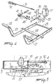
- the horizontal wood riving machine with safety means comprises a framework which is generally designated by the reference numeral 1 and is advantageously provided with rear wheels 2 for moving it easily and with a grip bar 3 arranged at the front.
- the framework 1 forms, in its upper part, a tubular case 4 for accommodating a pusher piston 5 which advantageously has a square housing that is arranged around the stem of the piston, whereas the body of the cylinder is accommodated inside the case 4; a telescopic coupling is thus provided.
- the case 4 has a bottom 6 that allows to rest the framework on the ground when the machine is not used; it is thus possible to arrange the machine in a vertical position, as shown in figure 3, reducing its space occupation.
- the pusher piston 5 is provided, at the front, with a presser plate 10 which faces a wedge-like riving knife 11 of the interchangeable type which can be mounted on the upper cross-member 12 of the device.
- the upper cross-member has two lateral supports 13 that in practice form the region for accommodating the log to be split.
- a motor 16 is furthermore connected to the framework 1 and drives a fluid-activated pump which, by means of a distribution unit 17, provides the fluid-activated means for actuating the piston 5.
- the particularity of the invention resides in the fact that there are two levers 20 and 21 for actuating the fluid-activated means; said levers are arranged side by side and are mutually spaced so that they require simultaneous actuation with both of the user's hands in order to perform the active stroke of the piston, thus constituting a considerable safety criterion since said simultaneous actuation prevents the user's hands from being placed in the piston movement region.
- the levers 20 and 21 have respective handles 22 and 23 and are pivoted, in a median portion, to a bar 24 which is supported by the fixed framework.
- an actuator 25 that runs parallel to the bar 24 and is supported at its ends by the ends of the levers 20 and 21.
- the actuator 25 acts on an L-shaped lever 26 which is pivoted to the framework, in a median portion, and has an actuation arm 27 that engages by contact the median portion of the actuator 25.
- the slider 28 of the distribution unit of the fluid-activated means 17 acts above the actuation arm 27.
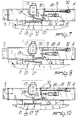
- the distribution unit 17 is configured so that a central position of the slider 28 corresponds to a neutral position, in which the motor is not activated, whereas when one acts by pushing on both levers 20 and 21 the slider 28 moves, so as to retract, consequently actuating the distribution unit 17 to produce the active stroke of the piston 5.
- the actuator tilts, as shown in figure 9, and the slider moves outwards with respect to the distribution unit 17, arranging itself in the neutral position in which it stops the piston.
- the machine is furthermore provided with an automatic stop device, and for this purpose a traction element 31 is connected to the stroke-limiting arm 30 of the L-shaped lever 26 and to a stroke-limiting retainer 32 that enters the case 4 and is actuated by the cylinder that retracts and reaches the end of its stroke.
- the piston by retracting into the case 4, once it has reached the end of its stroke, interacts with the stroke-limiting retainer 32 and by causing it to move, by means of the traction element 31, it makes the L-shaped lever 26 rotate, moving the slider 28 into the neutral position.
- the half-stroke limiting device has a bracket 40 which is slidingly mounted on the outside of the case 4 and has a sleeve 41 in which it is possible to detachably insert a half-stroke limiting pin 42 that interacts with the piston 5 that retracts into the case 4 and causes, in the manner described earlier, the rotation of the lever by virtue of the fact that there is a block 43 for connecting to the stroke-limiting arm 30 of the L-shaped lever 26.
- the piston continues its retracting stroke until it engages the stroke limiter 32 that stops it in the manner described earlier.
- the actuator 25 arranges itself at an angle and accordingly moves the distribution unit 17 with its slider into the neutral position, stopping the stroke of the pusher.
- Another important aspect is furthermore constituted by the fact that the machine stops automatically at its stroke limit and that said stroke limit can also be provided in an intermediate position.
- the materials employed may be any according to the requirements.
Landscapes
- Engineering & Computer Science (AREA)
- General Engineering & Computer Science (AREA)
- Life Sciences & Earth Sciences (AREA)
- Mechanical Engineering (AREA)
- Wood Science & Technology (AREA)
- Forests & Forestry (AREA)
- Bending Of Plates, Rods, And Pipes (AREA)
- Debarking, Splitting, And Disintegration Of Timber (AREA)
- Shearing Machines (AREA)
Applications Claiming Priority (2)
| Application Number | Priority Date | Filing Date | Title |
|---|---|---|---|
| ITMI940109A IT1269466B (it) | 1994-01-24 | 1994-01-24 | Struttura di macchina spaccalegna ad asse orizzontale con mezzi di sicurezza |
| ITMI940109 | 1994-01-24 |
Publications (1)
| Publication Number | Publication Date |
|---|---|
| EP0664190A1 true EP0664190A1 (de) | 1995-07-26 |
Family
ID=11367619
Family Applications (1)
| Application Number | Title | Priority Date | Filing Date |
|---|---|---|---|
| EP95100618A Withdrawn EP0664190A1 (de) | 1994-01-24 | 1995-01-18 | Holzspaltmaschine mit Sicherheitseinrichtung |
Country Status (2)
| Country | Link |
|---|---|
| EP (1) | EP0664190A1 (de) |
| IT (1) | IT1269466B (de) |
Cited By (3)
| Publication number | Priority date | Publication date | Assignee | Title |
|---|---|---|---|---|
| FR2851494A1 (fr) * | 2003-02-21 | 2004-08-27 | Rabaud Sa | Perfectionnement aux fendeuses de buches |
| EP1837147A1 (de) * | 2006-03-24 | 2007-09-26 | Scheppach Fabrikation von Holzbearbeitungsmaschinen GmbH | Holzspalter |
| AU2008100777B4 (en) * | 2008-08-15 | 2012-06-07 | Burders Lane Enterprises Pty Ltd. | Wood splitter |
Citations (4)
| Publication number | Priority date | Publication date | Assignee | Title |
|---|---|---|---|---|
| US2473167A (en) * | 1944-12-09 | 1949-06-14 | Denison Eng Co | Two-hand control |
| US2851072A (en) * | 1956-07-16 | 1958-09-09 | Harry H Gerjets | Wood splitting machine |
| US4782870A (en) * | 1987-10-30 | 1988-11-08 | Dennis Duerr | Portable wood splitter |
| DE4115838A1 (de) * | 1991-05-15 | 1992-11-19 | Steigerwald Rudolf Dipl Ing Fh | Holzspaltmaschine mit sicherheitsschaltung, beweglichen schutzverkleidungen und zufuehr- und entnahmevorrichtungen |
-
1994
- 1994-01-24 IT ITMI940109A patent/IT1269466B/it active IP Right Grant
-
1995
- 1995-01-18 EP EP95100618A patent/EP0664190A1/de not_active Withdrawn
Patent Citations (4)
| Publication number | Priority date | Publication date | Assignee | Title |
|---|---|---|---|---|
| US2473167A (en) * | 1944-12-09 | 1949-06-14 | Denison Eng Co | Two-hand control |
| US2851072A (en) * | 1956-07-16 | 1958-09-09 | Harry H Gerjets | Wood splitting machine |
| US4782870A (en) * | 1987-10-30 | 1988-11-08 | Dennis Duerr | Portable wood splitter |
| DE4115838A1 (de) * | 1991-05-15 | 1992-11-19 | Steigerwald Rudolf Dipl Ing Fh | Holzspaltmaschine mit sicherheitsschaltung, beweglichen schutzverkleidungen und zufuehr- und entnahmevorrichtungen |
Cited By (4)
| Publication number | Priority date | Publication date | Assignee | Title |
|---|---|---|---|---|
| FR2851494A1 (fr) * | 2003-02-21 | 2004-08-27 | Rabaud Sa | Perfectionnement aux fendeuses de buches |
| EP1837147A1 (de) * | 2006-03-24 | 2007-09-26 | Scheppach Fabrikation von Holzbearbeitungsmaschinen GmbH | Holzspalter |
| US8091595B2 (en) | 2006-03-24 | 2012-01-10 | Sheppach Fabrikation von Holzbearbeitungschinen GmbH | Wood splitter |
| AU2008100777B4 (en) * | 2008-08-15 | 2012-06-07 | Burders Lane Enterprises Pty Ltd. | Wood splitter |
Also Published As
| Publication number | Publication date |
|---|---|
| ITMI940109A1 (it) | 1995-07-24 |
| IT1269466B (it) | 1997-04-01 |
| ITMI940109A0 (it) | 1994-01-24 |
Similar Documents
| Publication | Publication Date | Title |
|---|---|---|
| US4700759A (en) | Wood splitter | |
| US4453580A (en) | Wood splitting device | |
| US4141396A (en) | Hydraulic log splitter | |
| US4289299A (en) | Hydraulic lifting jack including a safety device for an elevator therein | |
| GB905348A (en) | Log-splitter | |
| US3724256A (en) | Tube bender and cutter | |
| US4157105A (en) | Portable log splitter | |
| US4423759A (en) | Electrically powered log splitter | |
| US2667922A (en) | Machine for cutting sheet material | |
| US5472322A (en) | Positive displacement vacuum pump having a piston actuated by an alternative linear movement | |
| JPH0244733B2 (de) | ||
| US3738401A (en) | Apparatus for severing the root system of the tree from the trunk during the tree-felling operation | |
| US4252165A (en) | Log actuated log splitter | |
| GB2082977A (en) | Hoop-forming apparatus for steel straps | |
| US20060060262A1 (en) | Cycle shortener for log splitters | |
| EP0806271A3 (de) | Hydraulisches Versorgungssystem für Holzspalter | |
| US3995369A (en) | Cattle de-horning apparatus | |
| CZ283559B6 (cs) | Bezpečnostní štípací zařízení | |
| EP0917940A3 (de) | Spaltmaschine | |
| ITVI960041A1 (it) | Dispositivo e procedimento per la spinta della tavola da tagliare in una segatrice a disco | |
| ITMI940109A1 (it) | Struttura di macchina spaccalegna ad asse orizzontale con mezzi di sicurezza | |
| US3387525A (en) | Probing device on punch presses and the like | |
| US4630659A (en) | Winch-powered wood splitter | |
| EP1775084A1 (de) | Holzspaltgerät | |
| EP1775085A1 (de) | Holzspaltgerät |
Legal Events
| Date | Code | Title | Description |
|---|---|---|---|
| PUAI | Public reference made under article 153(3) epc to a published international application that has entered the european phase |
Free format text: ORIGINAL CODE: 0009012 |
|
| AK | Designated contracting states |
Kind code of ref document: A1 Designated state(s): AT CH DE IT LI |
|
| STAA | Information on the status of an ep patent application or granted ep patent |
Free format text: STATUS: THE APPLICATION HAS BEEN WITHDRAWN |
|
| 18W | Application withdrawn |
Withdrawal date: 19960202 |