EP0664185A2 - Holzbearbeitungszentrum - Google Patents
Holzbearbeitungszentrum Download PDFInfo
- Publication number
- EP0664185A2 EP0664185A2 EP95830006A EP95830006A EP0664185A2 EP 0664185 A2 EP0664185 A2 EP 0664185A2 EP 95830006 A EP95830006 A EP 95830006A EP 95830006 A EP95830006 A EP 95830006A EP 0664185 A2 EP0664185 A2 EP 0664185A2
- Authority
- EP
- European Patent Office
- Prior art keywords
- workpieces
- work table
- infeed
- machining
- sections
- Prior art date
- Legal status (The legal status is an assumption and is not a legal conclusion. Google has not performed a legal analysis and makes no representation as to the accuracy of the status listed.)
- Withdrawn
Links
- 238000003754 machining Methods 0.000 title claims abstract description 48
- 239000002023 wood Substances 0.000 title claims abstract description 10
- 230000000694 effects Effects 0.000 claims description 6
- 238000009826 distribution Methods 0.000 claims description 2
- 230000035515 penetration Effects 0.000 description 2
- 238000010923 batch production Methods 0.000 description 1
- 238000006243 chemical reaction Methods 0.000 description 1
- 238000006073 displacement reaction Methods 0.000 description 1
- 239000000428 dust Substances 0.000 description 1
- 238000000605 extraction Methods 0.000 description 1
- 230000002452 interceptive effect Effects 0.000 description 1
- 238000004519 manufacturing process Methods 0.000 description 1
- 239000000463 material Substances 0.000 description 1
Images
Classifications
-
- B—PERFORMING OPERATIONS; TRANSPORTING
- B23—MACHINE TOOLS; METAL-WORKING NOT OTHERWISE PROVIDED FOR
- B23Q—DETAILS, COMPONENTS, OR ACCESSORIES FOR MACHINE TOOLS, e.g. ARRANGEMENTS FOR COPYING OR CONTROLLING; MACHINE TOOLS IN GENERAL CHARACTERISED BY THE CONSTRUCTION OF PARTICULAR DETAILS OR COMPONENTS; COMBINATIONS OR ASSOCIATIONS OF METAL-WORKING MACHINES, NOT DIRECTED TO A PARTICULAR RESULT
- B23Q1/00—Members which are comprised in the general build-up of a form of machine, particularly relatively large fixed members
- B23Q1/25—Movable or adjustable work or tool supports
- B23Q1/64—Movable or adjustable work or tool supports characterised by the purpose of the movement
- B23Q1/66—Worktables interchangeably movable into operating positions
-
- B—PERFORMING OPERATIONS; TRANSPORTING
- B23—MACHINE TOOLS; METAL-WORKING NOT OTHERWISE PROVIDED FOR
- B23Q—DETAILS, COMPONENTS, OR ACCESSORIES FOR MACHINE TOOLS, e.g. ARRANGEMENTS FOR COPYING OR CONTROLLING; MACHINE TOOLS IN GENERAL CHARACTERISED BY THE CONSTRUCTION OF PARTICULAR DETAILS OR COMPONENTS; COMBINATIONS OR ASSOCIATIONS OF METAL-WORKING MACHINES, NOT DIRECTED TO A PARTICULAR RESULT
- B23Q1/00—Members which are comprised in the general build-up of a form of machine, particularly relatively large fixed members
- B23Q1/01—Frames, beds, pillars or like members; Arrangement of ways
- B23Q1/012—Portals
Definitions
- the present invention relates to a machine for working wood and similar materials, in particular a machine designed to perform boring and/or routing operations on workpieces with tools rotatable about vertical, horizontal or oblique axes, of the type widely referred to as a "machining centre".
- such machines consist in a load-bearing frame comprising a bed and, supported by the bed, a horizontal work table on which to position the pieces for machining (the workpieces in question include boards, battens and panels of wood or composition destined for batch production as parts for furniture manufacturing or industrial use).
- the work table is equipped with stops, push rods and reference elements distributed around the machining area and adjustable relative to the table in such a manner as to allow correct positioning of the workpieces on the horizontal surface.
- the frame also comprises a rigid gantry structure with enclosed ends, of which the bridging member or beam extends longitudinally above the work table and serves to support an overhung machining unit mounted slidably on ways afforded by the selfsame member or beam; the machining unit is capable thus of movement along two mutually perpendicular axes (X - Y) and "exploring" the entire area compassed by the work table.
- Conventional machining units of this type generally comprise one or more spindle heads carrying one or a plurality of tools, each rotatable about a vertical, horizontal or oblique axis and capable in turn of movement along their respective axes so as to obtain the required depth of penetration into the work.
- the infeed and subsequent outfeed of the workpieces to and from the table is effected along a direction transverse or normal to the main longitudinal axis of the machine: a solution dictated not least by the architecture of the gantry structure, with its enclosed ends.
- a further drawback betrayed by current machines of this type stems from a structural shortcoming: more exactly, it has been observed that with the mass of the machining unit set in motion along the ways and in relation to the inertia axis of the longitudinal member of the rigid gantry structure, torsional and dynamic effects can be generated in the structure both by the total displacement of this same mass and by the reaction of the tool in operation; these effects must of course create a certain instability in the structure and may produce a negative impact on the precision of the work.
- the object of the present invention is to overcome the drawbacks mentioned above through the adoption of a wood machining centre featuring compact dimensions and precise operation, capable of high output, and designed principally to operate in conditions of zero down time achieved by virtue of the fact that the work is fed not in a direction transverse to the longitudinal axis of the machine, but rather in a direction parallel to the selfsame longitudinal axis of the machine.
- the invention relates to a machine such as can be used preferably for boring and/or routing workpieces in wood, denoted 1, and more exactly to a machining centre equipped with tools 2 which, in the example illustrated, operate with axes Z vertically disposed; the centre might equally well be equipped with tools rotating about oblique or horizontal axes, the tools being capable in any event of movement along these same axes to determine the depth of penetration into the work beneath.
- Such machines comprise a horizontal table 3 serving to support the workpieces 1, which are directed into the work area by way of an infeed station 4, and removed by way of a relative outfeed station 5.
- the work table 3 is surmounted by a frame 6 serving to support a machining unit 7 generally comprising one or more motorized spindles 23 of conventional embodiment, to which the aforementioned tools 2 are secured, and/or simple chucks accepting drill bits, together with relative dust extraction systems 24.
- the machining unit 7 is capable of movement along two mutually perpendicular axes X and Y occupying a horizontal plane parallel with and compassing the entire surface of the work table 3 beneath.
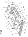
- the work table 3 is divided into two identical half-sections, denoted 8 and 9, resulting in the creation of two independent machining and conveying lines; workpieces 1 advance along a direction F parallel with the longitudinal axis of the table 3, and are directed onto the two half-sections 8 and 9 at one end from respective independent infeed stations 4 and 4a, whilst at the opposite end, the two half-sections 8 and 9 connect with corresponding outfeed stations 5 and 5a by way of which the workpieces 1 are distanced likewise in a direction F1 parallel with the longitudinal axis of the table 3.
- the effect of such an arrangement, as discernible clearly in fig 1, is to create two independent and mutually non-interfering paths with entry, machining and exit stages along which the workpieces 1 are directed.
- each of the two half-sections is equipped in a substantially central area with means 13 by which to position the workpieces 1; such means 13 are of conventional type, consisting in stops 25 and push rods 26 (generally pneumatic actuators) distributed along each of the work areas created by the two half-sections.
- the positioning means comprise feeder-conveyor means 14 (likewise conventional and consisting, for example, in pairs of adjustable belts as indicated in fig 2) by which the workpieces 1 are admitted to and removed from the corresponding half-section 8 and 9.
- the infeed and outfeed stations 4, 4a and 5, 5a are each embodied preferably as power driven conveyor tables 15 of conventional type, arranged in pairs one alongside the other and connected with no break in continuity to the relative extremities of the two half-sections 8 and 9.
- the infeed and outfeed stations 4, 4a and 5, 5a are all linked to a sorting lane 16 allowing distribution of the workpieces 1 before or after machining; the sorting lane 16 extends parallel with the two machining and conveying lines, interconnecting the areas occupied by the infeed and outfeed stations 4, 4a and 5, 5a, such that the machine can be connected with other stations to or from which the workpieces 1 might be directed.
- the frame 6 is composed of a pair of fixed straddle bearers 10 and 11 positioned in mutual opposition and interposed between the ends of the work table 3 and the corresponding infeed and outfeed stations 4, 4a and 5, 5a, respectively.
- each straddle bearer 10 and 11 are disposed on opposite sides of the work table 3 at each respective end, thereby allowing an unhindered connection between the two half-sections 8 and 9 and the relative infeed and outfeed stations 4, 5, and 4a, 5a.
- the top parts of the two straddle bearers 10 and 11 are interconnected by relative means of support 12 positioned over the work table 3 and rendered capable of movement along one of the two mutually perpendicular axes X and Y aforementioned (freedom of movement on one axis or the other will depend on which of the two preferred solutions is adopted, as explained in due course).
- the machining unit 7 is mounted overhung to these same support means 12 with the ability to traverse over every part of the surface area compassed by the two half-sections 8 and 9 making up the work table 3, in such a manner that workpieces 1 can be machined on one half-section 8 or 9 at the same time as further workpieces undergo infeed and/or outfeed operations on the other half-section.
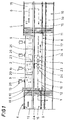
- a single horizontal beam 17 capable of movement along the 'Y' axis, and therefore transversely to the longitudinal axis of the work table 3, whilst the machining unit 7 traverses longitudinally along the beam 17, hence on the 'X' axis, coupled slidably to corresponding first ways 18 afforded by the beam 17 itself.
- the beam 17 is mounted slidably to the horizontal members of the two straddle bearers 10 and 11 which in their turn afford respective second horizontal ways 19.
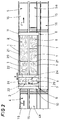
- a second solution illustrated (see fig 3), use is made of one or more horizontal beams (one such beam, denoted 29, is indicated by way of example) capable of movement along the 'X' axis, hence in a direction parallel to the longitudinal axis of the work table 3; to this end, the opposite ends of the beam 29 are coupled with relative mutually parallel third fixed ways 21 extending between and supported by the two straddle bearers 10 and 11.
- a machining unit 7 mounted internally of the beam 29 is coupled slidably to corresponding fourth guides 22 afforded by the second beam 29 itself, and rendered capable thus of movement along the 'Y' axis transversely to the work table 3.
- the machining unit 7 will come into operation and engage the workpieces 1 on the corresponding half-section 8, traversing along the beam 17 parallel with the X axis (see arrow X); the necessary movements along the Y axis are effected by translating the entire beam 17, and those along the Z axis by lowering and raising the tool (see arrow Z in fig 2).
- the beam 17 traverses along the Y axis to bring the machining unit 7 over the remaining half-section 9 of the work table 3, whereupon the relative workpieces 1 will be machined in identical fashion.
- the opposite half-section 8 is liberated of the workpieces 1 machined previously, by way of the outfeed station 5a, and prepared with further workpieces 1 brought in through the infeed station 4a (see arrow F).
- the beam 17 is traversed and the machining unit 7 can proceed without any delay whatever to engage the new pieces already positioned on the half-section 8 opposite.
- this half-section 9 will now be emptied and refilled in the same way as the half-section 8 opposite, the machined workpieces 1 being removed by way of the outfeed station 5 and a further set of workpieces entering via the infeed station 4.
- the operations effected thus far remain essentially the same, the only difference being in the positioning of the machining unit 7: movement along the X axis being effected by traversing the relative beam 29 along the fixed third ways 21, and movement along the Y axis by traversing the machining unit 7 along the fourth ways 22 internally of the beam 29.
- the design of a wood machining centre (typically for boring or routing operations) according to the present invention will thus allow workpieces to be machined at speed, while maintaining high standards of precision and eliminating down time thanks to the particular structure of the work table.
- the structure in question is based on the notion of parallelizing machining operations by the creation two independent lines, each capable of infeeding, machining and outfeeding a succession of workpieces without affecting the operation of the other, such that the tool can operate continuously and the time not effectively engaged in machining operations on either half of the work table can be "covered".
- a parallel lines structure of this type also enables a significant reduction in the overall dimensions of the machine, not obtainable hitherto in conventional designs.
- the gantry type frame can carry one or a plurality of machining units and is arranged in such a way as to compass a field of action double the size of the stock boards or panels in order to allow operation on either half of the field at any time (in effect, with the spindle heads alternating between the two halves); at the same time, the frame itself remains compact in both of the solutions illustrated, and unaffected by torsional or dynamic stresses.
- An additional and decidedly pertinent advantage of the machining centre disclosed is that work of any given dimensions can be handled, including boards or panels of considerable surface area equivalent even to the sum of the two half-sections, albeit down time cannot be eliminated in this instance; wide boards and panels are positioned on the work table and guided faultlessly beneath the gantry, their entire surface area covered by the machining unit, without any need for recourse to special or non-standard machinery or equipment.
Landscapes
- Engineering & Computer Science (AREA)
- Mechanical Engineering (AREA)
- Machine Tool Units (AREA)
Applications Claiming Priority (2)
| Application Number | Priority Date | Filing Date | Title |
|---|---|---|---|
| ITBO940016 | 1994-01-21 | ||
| ITBO940016A IT1273219B (it) | 1994-01-21 | 1994-01-21 | Macchina per la lavorazione di pezzi in legno |
Publications (2)
| Publication Number | Publication Date |
|---|---|
| EP0664185A2 true EP0664185A2 (de) | 1995-07-26 |
| EP0664185A3 EP0664185A3 (de) | 1995-12-06 |
Family
ID=11339417
Family Applications (1)
| Application Number | Title | Priority Date | Filing Date |
|---|---|---|---|
| EP95830006A Withdrawn EP0664185A3 (de) | 1994-01-21 | 1995-01-13 | Holzbearbeitungszentrum. |
Country Status (2)
| Country | Link |
|---|---|
| EP (1) | EP0664185A3 (de) |
| IT (1) | IT1273219B (de) |
Cited By (2)
| Publication number | Priority date | Publication date | Assignee | Title |
|---|---|---|---|---|
| EP0747165A1 (de) * | 1995-06-07 | 1996-12-11 | BIESSE S.p.A. | Mehrsparige Werkzeugmaschine zur Bearbeitung von Platten |
| EP1882570A1 (de) * | 2006-07-25 | 2008-01-30 | Homag Holzbearbeitungssysteme AG | Bearbeitungszentrum zur Bearbeitung lang gestreckter Werkstücke |
Family Cites Families (4)
| Publication number | Priority date | Publication date | Assignee | Title |
|---|---|---|---|---|
| US3981605A (en) * | 1975-11-03 | 1976-09-21 | Frank Tessitore | X-Y table for machining |
| IT1248990B (it) * | 1990-06-25 | 1995-02-11 | Vittorio Alberti S P A | Macchina utensile a teste multiple particolarmente studiata per la lavorazione di pannelli |
| FR2669253B1 (fr) * | 1990-11-21 | 1993-01-22 | Brunet Alain | Dispositif de transfert pour installation de decoupe de toles. |
| DE9303614U1 (de) * | 1993-03-12 | 1993-04-29 | MAW Maschinenbau GmbH, 4900 Herford | Vorrichtung zum Bearbeiten von plattenförmigen Werkstücken |
-
1994
- 1994-01-21 IT ITBO940016A patent/IT1273219B/it active IP Right Grant
-
1995
- 1995-01-13 EP EP95830006A patent/EP0664185A3/de not_active Withdrawn
Cited By (2)
| Publication number | Priority date | Publication date | Assignee | Title |
|---|---|---|---|---|
| EP0747165A1 (de) * | 1995-06-07 | 1996-12-11 | BIESSE S.p.A. | Mehrsparige Werkzeugmaschine zur Bearbeitung von Platten |
| EP1882570A1 (de) * | 2006-07-25 | 2008-01-30 | Homag Holzbearbeitungssysteme AG | Bearbeitungszentrum zur Bearbeitung lang gestreckter Werkstücke |
Also Published As
| Publication number | Publication date |
|---|---|
| ITBO940016A1 (it) | 1995-07-21 |
| ITBO940016A0 (it) | 1994-01-21 |
| IT1273219B (it) | 1997-07-07 |
| EP0664185A3 (de) | 1995-12-06 |
Similar Documents
| Publication | Publication Date | Title |
|---|---|---|
| KR100209920B1 (ko) | 공구조립체의 양쪽에서 개별 제어식 파지 이송 수단에 의해 파지된 공작물을 가공하기 위한 다중 스핀들 기계 | |
| US4457193A (en) | Machine-tool comprising two opposed coaxial spindles | |
| EP0583085B1 (de) | Gerät zum Positionieren für Mehrspindelbearbeitungen | |
| US5564483A (en) | Unit for machining workpieces, in particular wood | |
| US5704262A (en) | Multiple-spindle lathe | |
| US4711016A (en) | Flexible manufacturing unit | |
| EP1250976B1 (de) | Werkzeugmaschinen zum bearbeiten von länglichen Werkstücken | |
| EP4316702B1 (de) | Numerisch gesteuerte mehrspindeldrehmaschine | |
| US20030182782A1 (en) | Machining system with multiaxial movement | |
| US5343604A (en) | Combined working machine | |
| ES2153687T3 (es) | Maquina de mecanizado. | |
| GR3000276T3 (en) | Pressure beam for sawing machines | |
| US4449986A (en) | Machine for guiding numerically controlled supports for tools used in woodworking operation | |
| US5730195A (en) | Machining center for the machining of flat workpieces | |
| EP1002620B1 (de) | Werkzeugmaschine mit Schwenktischen | |
| EP0664185A2 (de) | Holzbearbeitungszentrum | |
| US20080000072A1 (en) | Flexible Transfer Machine | |
| KR19990082125A (ko) | 다수의 스핀들을 갖는 공작기계 | |
| CN108747227A (zh) | 一种空调压缩机轴承座的加工方法及其加工生产线 | |
| JPH0639032B2 (ja) | 工作物を加工する加工ユニツトで工具支持体を交換するための装置 | |
| CN208825952U (zh) | 一种空调压缩机轴承座的加工生产线 | |
| US4665784A (en) | Machine tool | |
| JPH0246321B2 (de) | ||
| SU1660938A1 (ru) | Гибкий производственный модуль | |
| US6536312B1 (en) | Compound machining center compound machining method and machining tool |
Legal Events
| Date | Code | Title | Description |
|---|---|---|---|
| PUAI | Public reference made under article 153(3) epc to a published international application that has entered the european phase |
Free format text: ORIGINAL CODE: 0009012 |
|
| AK | Designated contracting states |
Kind code of ref document: A2 Designated state(s): DE ES FR GB |
|
| PUAL | Search report despatched |
Free format text: ORIGINAL CODE: 0009013 |
|
| AK | Designated contracting states |
Kind code of ref document: A3 Designated state(s): DE ES FR GB |
|
| STAA | Information on the status of an ep patent application or granted ep patent |
Free format text: STATUS: THE APPLICATION HAS BEEN WITHDRAWN |
|
| 18W | Application withdrawn |
Withdrawal date: 19960124 |