EP0664152B1 - Fahrzeug zum Mischen und Abgeben von tierischen Futter - Google Patents
Fahrzeug zum Mischen und Abgeben von tierischen Futter Download PDFInfo
- Publication number
- EP0664152B1 EP0664152B1 EP95610003A EP95610003A EP0664152B1 EP 0664152 B1 EP0664152 B1 EP 0664152B1 EP 95610003 A EP95610003 A EP 95610003A EP 95610003 A EP95610003 A EP 95610003A EP 0664152 B1 EP0664152 B1 EP 0664152B1
- Authority
- EP
- European Patent Office
- Prior art keywords
- vehicle body
- mixing
- vehicle
- paddles
- dispensing
- Prior art date
- Legal status (The legal status is an assumption and is not a legal conclusion. Google has not performed a legal analysis and makes no representation as to the accuracy of the status listed.)
- Expired - Lifetime
Links
- 241001465754 Metazoa Species 0.000 title claims description 15
- 238000005303 weighing Methods 0.000 claims description 21
- 239000000463 material Substances 0.000 claims description 15
- 239000004615 ingredient Substances 0.000 claims description 10
- 239000010902 straw Substances 0.000 claims description 7
- 239000003381 stabilizer Substances 0.000 claims description 3
- 241000283690 Bos taurus Species 0.000 claims description 2
- 238000005096 rolling process Methods 0.000 claims description 2
- 244000025254 Cannabis sativa Species 0.000 claims 1
- 239000000203 mixture Substances 0.000 claims 1
- 230000003019 stabilising effect Effects 0.000 claims 1
- 238000010276 construction Methods 0.000 description 5
- 230000000694 effects Effects 0.000 description 2
- 238000000034 method Methods 0.000 description 2
- 230000000087 stabilizing effect Effects 0.000 description 2
- 239000004677 Nylon Substances 0.000 description 1
- 230000002411 adverse Effects 0.000 description 1
- 230000005540 biological transmission Effects 0.000 description 1
- 238000012423 maintenance Methods 0.000 description 1
- 229920001778 nylon Polymers 0.000 description 1
- 230000000284 resting effect Effects 0.000 description 1
- 239000000725 suspension Substances 0.000 description 1
Images
Classifications
-
- A—HUMAN NECESSITIES
- A01—AGRICULTURE; FORESTRY; ANIMAL HUSBANDRY; HUNTING; TRAPPING; FISHING
- A01K—ANIMAL HUSBANDRY; AVICULTURE; APICULTURE; PISCICULTURE; FISHING; REARING OR BREEDING ANIMALS, NOT OTHERWISE PROVIDED FOR; NEW BREEDS OF ANIMALS
- A01K5/00—Feeding devices for stock or game ; Feeding wagons; Feeding stacks
- A01K5/001—Fodder distributors with mixer or shredder
- A01K5/002—Fodder distributors with mixer or shredder with mixing or shredding element rotating on horizontal axis
-
- B—PERFORMING OPERATIONS; TRANSPORTING
- B01—PHYSICAL OR CHEMICAL PROCESSES OR APPARATUS IN GENERAL
- B01F—MIXING, e.g. DISSOLVING, EMULSIFYING OR DISPERSING
- B01F33/00—Other mixers; Mixing plants; Combinations of mixers
- B01F33/50—Movable or transportable mixing devices or plants
- B01F33/502—Vehicle-mounted mixing devices
-
- B—PERFORMING OPERATIONS; TRANSPORTING
- B01—PHYSICAL OR CHEMICAL PROCESSES OR APPARATUS IN GENERAL
- B01F—MIXING, e.g. DISSOLVING, EMULSIFYING OR DISPERSING
- B01F27/00—Mixers with rotary stirring devices in fixed receptacles; Kneaders
- B01F27/05—Stirrers
- B01F27/11—Stirrers characterised by the configuration of the stirrers
- B01F27/114—Helically shaped stirrers, i.e. stirrers comprising a helically shaped band or helically shaped band sections
-
- B—PERFORMING OPERATIONS; TRANSPORTING
- B01—PHYSICAL OR CHEMICAL PROCESSES OR APPARATUS IN GENERAL
- B01F—MIXING, e.g. DISSOLVING, EMULSIFYING OR DISPERSING
- B01F27/00—Mixers with rotary stirring devices in fixed receptacles; Kneaders
- B01F27/23—Mixers with rotary stirring devices in fixed receptacles; Kneaders characterised by the orientation or disposition of the rotor axis
- B01F27/232—Mixers with rotary stirring devices in fixed receptacles; Kneaders characterised by the orientation or disposition of the rotor axis with two or more rotation axes
- B01F27/2322—Mixers with rotary stirring devices in fixed receptacles; Kneaders characterised by the orientation or disposition of the rotor axis with two or more rotation axes with parallel axes
-
- B—PERFORMING OPERATIONS; TRANSPORTING
- B01—PHYSICAL OR CHEMICAL PROCESSES OR APPARATUS IN GENERAL
- B01F—MIXING, e.g. DISSOLVING, EMULSIFYING OR DISPERSING
- B01F27/00—Mixers with rotary stirring devices in fixed receptacles; Kneaders
- B01F27/60—Mixers with rotary stirring devices in fixed receptacles; Kneaders with stirrers rotating about a horizontal or inclined axis
Definitions
- the invention relates to a feed vehicle for mixing feed especially based on straw for cattle and dispensing said feed and of the type comprising a vehicle body, the bottom being cylindrical and in which a driven mixing rotor with paddle arms is arranged in the longitudinal direction of the vehicle body, the paddle arms at their ends being provided with paddles for mixing the feed ingredients and dispensing of the ready feed through a hinged hatch in the side.
- Prior art constructions have their dispensing hatches placed at the front of the feed truck and the paddles are slanted such that they convey the feed towards the hatch. This conveying of the material also takes place during the actual mixing of the feed and causes an undesirable pressure against the front of the vehicle body. Furthermore, the mixing process is somewhat inadequate.
- the problem is solved by slanting the paddles at the rear of the mixing rotor such that they convey the material forwardly in the vehicle body whereas the paddles at the front are slanted such that they convey the material backwardly in the truck and that the dispensing hatch be placed in the area where the opposing paddles meet each other.
- the paddles may be successively spaced approximately 240 degrees with the exception of the two paddles at the intersection of the two sets of paddles being placed exactly opposite one another.
- mixing rotor may be placed such that the distance to the side of the vehicle body is increased in the rotating direction of the rotor and the paddles are also placed such that their tail ends rise from the side of the vehicle body whereby material being wedged underneath the paddles is eliminated which is the tendency in the prior art constructions.
- inwardly extending cutters can be placed at the inner side of the vehicle body.
- these cutters are detachably fastened in a welded-on mounting.
- the cutters are exposed to heavy wear and are to be replaced frequently which is rather complicated and time consuming.
- the cutters may be fastened in a holder designed for an outside fastening to the vehicle body in which there are slots through which slots the cutters protrude into the inner side of the vehicle body.
- the counter cutters may thus be replaced working from the outside which makes it much easier and is a major simplification, similarly, the cutters can be removed if they are not required for specific purposes.
- the inside of the vehicle body then appears smooth and without protruding mountings for the cutters.
- the vehicle body For controlling the quantity of feed and the mixing ratio of the ingredients as well as the dispensed feed quantity the vehicle body is provided with weighing cells.
- the vehicle body may be provided with three weighing cells. At the rear one cell is placed at either side. The cell is placed in a short horizontal support structure having a downwardly extending link with a link seat fastened to a holder in the chassis frame of the feed truck. At the front the vehicle body is supported by an upright top link connected to the vehicle body by a link seat via a weighing cell and where the lower end of the top link is fastened to the chassis frame of the vehicle such that it can turn about a longitudinal axis.
- a stabilizer may be fastened underneath said body to this body and to the chassis frame to counteract rolling of the vehicle body. This floating suspension of the vehicle body causes a very accurate function of the weighing cells thereby yielding a precise weighing result.
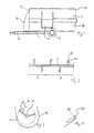
- Fig. 1 of the drawing shows purely schematically a lateral view of a vehicle for mixing and dispensing animal feed
- a vehicle body 2 mounted on a chassis provided with drive wheels 6 at the rear.
- a pole 8 at the front the feed truck is designed for being drawn by a tractor.
- a mixing rotor is placed between the end walls 10, 12, said rotor being rotated by a transmission placed in an enclosure 16 at the front end of the vehicle body.
- a hinged hatch 18 for dispensing the ready mixed feed.
- an unloading roller or elevator can be arranged.
- the mixing rotor 14 is designed as schematically illustrated in Fig. 2.
- the mixing rotor comprises five paddle arms 20 of a rectangular cross section tapering towards its ends where a paddle 20 is placed.
- the paddle arms are divided into two sections A, B meeting at the dispensing hatch 18.
- At the front of the vehicle body the paddles are placed so that they convey the material backwardly towards the hatch while the paddles at the rear are placed so that these convey the material forwardly likewise towards the hatch.
- the first paddle arm in each section is displaced 180 degrees.
- the succeeding arms are displaced 240 degrees relative the preceding one whereby it is found that an extremely efficient mixing of the ingredients is achieved.
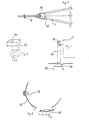
- the mixing rotor is seated a little eccentric relative the cylindrical portion 26 of the vehicle body such that the paddles at the entrance to the cylindrical portion 26 of the vehicle body are virtually in contact with the side wall whereas the further travel results in an increasing distance from the wall, cf. Fig. 3. Furthermore the paddles 22 are placed so that their tail ends raise away from the vehicle side 24, cf. Fig. 4. The material that would otherwise tend to wedge beneath the paddles causing the rotor in adverse cases to stick escapes due to the increasing distance to the wall and the slip of the paddles in the rearward direction.
- One of the feed ingredients is typically whole straw bales that are shredded by the mixing rotor 14 and a knife arrangement 28 on the cylindrical portion 26 of the vehicle body at the entry into this.
- the knife-shaped cutters are mounted at the outside of the vehicle body and extend into the interior through slots in the side especially designed for this purpose.
- the knives are mounted in a base fastened to the outside of the vehicle body allowing the knives to be externally replaced, these knives being extremely prone to heavy wear and consequently in need of frequent replacements.
- the vehicle body For weighing the ingredients the whole quantity of feed and the dispensed quantity of feed, the vehicle body rests on weighing cells.
- the electric equipment including digital display as well as hydraulic control valves are aggregated in a control unit placed at the end of a pivotal telescopic arm, which is not shown, at the front of the feed truck.
- the vehicle body At the rear the vehicle body is supported at a weighing cell 30 at either side.
- the weighing cell is mounted at a support structure 32 provided with a link seat 34 above which the weighing cell is fastened to a holder on the chassis, cf. Fig. 5.
- a weighing cell 40 is placed on a cross piece 42 in the former.
- a top link 44 which is fastened so that it can pivot about a transverse axis while the upper end of the top link is provided with a link seat 46 with which the link is fastened to and supports the vehicle body.
- the vehicle body is thus floatingly suspended on the weighing cells resulting in obtaining a precise weighing result, as inaccuracies from torsions in the chassis are eliminated.
- Fig. 9 of the drawing is shown an essential part of the feed truck where the vehicle body is arranged such that it can be tilted about an axis through the link seat 34 in the support structure for the rearmost weighing cells.
- the vehicle body 2 is guided by a leg 44 at either side, these legs resting on the outside of the chassis frame.
- a wedge 46 having its bolts in elongate holes, the wedge being capable of being displaced forwardly and backwardly.
- a nylon roll 48 is arranged sliding at the wedges. Possible inaccuracies and wobbling in the guiding means are removed by adjusting the wedges.
- the top link is here a hydraulic cylinder.
- the vehicle body can be caused to tilt forwardly as well as backwardly whereby the pressure on the ends of the vehicle body may be controlled.
- the material seeks forwardly whereby the rear end be pressure relieved and vice versa when the vehicle body be caused to tilt backwardly.
- the invention thus provides a significantly improved construction of a vehicle for mixing and dispensing animal feed having better mixing abilities and easier maintenance.
Landscapes
- Life Sciences & Earth Sciences (AREA)
- Environmental Sciences (AREA)
- Chemical & Material Sciences (AREA)
- Chemical Kinetics & Catalysis (AREA)
- Birds (AREA)
- Animal Husbandry (AREA)
- Biodiversity & Conservation Biology (AREA)
- Apparatuses For Bulk Treatment Of Fruits And Vegetables And Apparatuses For Preparing Feeds (AREA)
Claims (7)
- Fahrzeug zum Mischen und Abgeben von Tierfutter zur Verwendung zum Mischen von Futter, insbesondere auf der Basis von Strohmaterialien, wie z.B. Stroh, Heu und Gras für Rinder, und zum Abgeben des Futters, der Bauart, die ein Fahrgestell (4) und einen Fahrzeugaufbau (2) aufweist, dessen Bodenabschnitt (26) zylindrisch ist und in dem ein einzelner angetriebener Mischrotor (14) mit Paddelarmen (20) in Längsrichtung des Fahrzeugaufbaus angeordnet ist, welche Paddelarme an ihren Enden mit Paddeln (22) zum Mischen der Futterinhaltsstoffe und Abgeben des fertigen Futters durch eine gelenkig gehalterte Klappe (18) in der Seite des Fahrzeugaufbaus versehen sind, dadurch gekennzeichnet, daßder Mischrotor einen hintersten Abschnitt (B) und einen vorderen Abschnitt (A) enthält, wobei die Paddel (22) an dem hintersten Abschnitt (B) des Mischrotors in der Weise geneigt sind, daß sie das Material in dem Fahrzeugaufbau nach vorne fördern, während die Paddel an dem vorderen Abschnitt (A) in der Weise geneigt sind, daß sie das Material in dem Fahrzeug nach hinten fördern, und daß die Ausgabeklappe (18) dort positioniert ist, wo die in entgegengesetzten Richtungen wirkenden Paddelabschnitte (A, B) aufeinandertreffen, undwobei das Kippen des Fahrzeugaufbaus sowohl nach vorne als auch nach hinten relativ zu dem Fahrgestell veranlaßt werden kann, wodurch der Druck des in dem Fahrzeugaufbau enthaltenen Tierfutters auf dessen Enden zusätzlich gesteuert werden kann.
- Fahrzeug zum Mischen und Abgeben von Tierfutter nach Anspruch 1, bei welchem die Paddel (20) aufeinanderfolgend in Abständen von 240 Grad angeordnet sind, mit Ausnahme der beiden Paddel an dem Schnittpunkt der beiden Paddelsätze, welche beiden Paddel um 180 Grad zueinander versetzt sind.
- Fahrzeug zum Mischen und Abgeben von Tierfutter nach Anspruch 1 oder 2, bei welchem der Mischrotor (14) in dem zylindrischen Abschnitt (26) des Fahrzeugaufbaus in der Weise exzentrisch angeordnet ist, daß der Abstand von den Paddeln (22) zu der Seite des Fahrzeugaufbaus in Drehrichtung des Rotors sukzessive zunimmt.
- Fahrzeug zum Mischen und Abgeben von Tierfutter nach Anspruch 3, bei welchem die Paddel in der Weise angeordnet sind, daß das hintere Ende von der Seite (24) ansteigt.
- Fahrzeug zum Mischen und Abgeben von Tierfutter nach Anspruch 1, versehen mit Schneidmessern (28) an der Innenseite des Fahrzeugaufbaus zum Schneiden von Futterinhaltsstoffen, wie z.B. Strohballen, bei welchem die Schneidmesser (28) in Haltern zur Befestigung von außen am Fahrzeugaufbau (2) befestigt sind, in welchem Schlitze vorhanden sind, durch die die Gegenschneidmesser in das Innere des Fahrzeugaufbaus verlaufen.
- Fahrzeug zum Mischen und Abgeben von Tierfutter nach Anspruch 1, bei dem der Fahrzeugaufbau auf Wägezellen (30, 40) zum Wiegen der Futterinhaltsstoffe und der Futtermischung ruht, wobei am hinteren Teil eine Wägezelle (30) auf beiden Seiten auf einer kurzen horizontalen Halterung (32) sitzend plaziert ist, die ein nach unten verlaufendes Verbindungselement hat, das mit einem Verbindungssitz (34) versehen ist. der an einem Halter an dem Fahrgestellrahmen des Fahrzeugaufbaus befestigt ist. wobei der Fahrzeugaufbau (2) an seiner Vorderseite durch ein aufrechtes oberes Verbindungselement getragen wird, das mit dem Fahrzeugaufbau durch einen Verbindungssitz (46) verbunden ist, und wobei das untere Ende des Verbindungselements über eine Achse auf einer Wägezelle (40) steht, die an dem Fahrgestellrahmen (4) des Fahrzeugs befestigt ist.
- Fahrzeug zum Mischen und Abgeben von Tierfutter nach Anspruch 6, bei welchem zur Stabilisierung des Fahrzeugaufbaus (2) ein horizontaler Stabilisator (48) unter diesem angeordnet ist, der mit dem Fahrzeugaufbau (2) und dem Fahrgestellrahmen (4) verbunden ist, um einem Rollen des Fahrzeugaufbaus entgegenzuwirken.
Applications Claiming Priority (3)
| Application Number | Priority Date | Filing Date | Title |
|---|---|---|---|
| DK009894A DK9894A (da) | 1994-01-21 | 1994-01-21 | Fodervogn |
| DK98/94 | 1994-01-21 | ||
| DK9894 | 1994-01-21 |
Publications (2)
| Publication Number | Publication Date |
|---|---|
| EP0664152A1 EP0664152A1 (de) | 1995-07-26 |
| EP0664152B1 true EP0664152B1 (de) | 2001-10-04 |
Family
ID=8089713
Family Applications (1)
| Application Number | Title | Priority Date | Filing Date |
|---|---|---|---|
| EP95610003A Expired - Lifetime EP0664152B1 (de) | 1994-01-21 | 1995-01-23 | Fahrzeug zum Mischen und Abgeben von tierischen Futter |
Country Status (4)
| Country | Link |
|---|---|
| EP (1) | EP0664152B1 (de) |
| DE (1) | DE69522973D1 (de) |
| DK (2) | DK9894A (de) |
| WO (1) | WO1995019694A1 (de) |
Families Citing this family (2)
| Publication number | Priority date | Publication date | Assignee | Title |
|---|---|---|---|---|
| BE1025447B1 (nl) * | 2017-08-01 | 2019-03-04 | Debutrac Bvba | Verbeterde meng- en verdeelinrichting voor veevoeder |
| CN110169230A (zh) * | 2018-12-28 | 2019-08-27 | 河南科技学院 | 一种棉花种子考种用搅拌桨叶 |
Family Cites Families (15)
| Publication number | Priority date | Publication date | Assignee | Title |
|---|---|---|---|---|
| GB134451A (en) * | 1919-02-08 | 1919-11-06 | Asbjorn Sonsthagen | An Improved Machine for Mixing Liquid, Semi-liquid or Viscid Materials. |
| US1833220A (en) * | 1928-04-09 | 1931-11-24 | Louis S Loeb | Mixing vat |
| FR1277015A (fr) * | 1960-12-29 | 1961-11-24 | Draiswerke G M B H Fa | Perfectionnements apportés aux mélangeurs à fonctionnement discontinu |
| AU3543868A (en) * | 1968-03-22 | 1970-07-23 | R. J. Moufang Pty. Limited | Improvements in tankers for transport of bulk dry granular materials |
| US3482821A (en) * | 1968-03-25 | 1969-12-09 | Everett C Blackwood | Utility farm vehicle for mixing and discharging bulk material |
| US3599939A (en) * | 1969-03-26 | 1971-08-17 | Louis M O Brien | Trailer-type liquid carrier and mixer |
| DE2336975A1 (de) * | 1973-07-20 | 1975-02-06 | Heinrich Dove | Vorrichtung zum entladen von getreide von kippwagen |
| GB2076678B (en) * | 1980-05-29 | 1983-09-21 | Howard Machinery Ltd | Mixing and dispensing machine for animal feed |
| US4364667A (en) * | 1981-02-06 | 1982-12-21 | Reiner Ralph | Mixing and transport conveyor |
| JPS5827699A (ja) * | 1981-08-11 | 1983-02-18 | Yamada Koji | 廃棄物の処理方法および装置 |
| FI71094C (fi) * | 1981-12-31 | 1986-11-24 | Neste Oy | Anordning foer transport och dosering av kornigt material |
| DE3728710C2 (de) * | 1987-08-28 | 1997-08-21 | Loedige Maschbau Gmbh Geb | Mischer zum Mischen von Feststoffschüttungen |
| IE59113B1 (en) * | 1988-09-28 | 1994-01-12 | Hughes Patrick | Apparatus for mixing and dispensing material |
| IE64445B1 (en) * | 1989-11-08 | 1995-08-09 | Salford Eng | Apparatus for breaking up blocks of fibrous material |
| AU5578894A (en) * | 1992-11-13 | 1994-06-08 | Transweight Nz Limited | Load cell arrangement |
-
1994
- 1994-01-21 DK DK009894A patent/DK9894A/da not_active Application Discontinuation
-
1995
- 1995-01-23 EP EP95610003A patent/EP0664152B1/de not_active Expired - Lifetime
- 1995-01-23 WO PCT/DK1995/000031 patent/WO1995019694A1/en not_active Ceased
- 1995-01-23 DE DE69522973T patent/DE69522973D1/de not_active Expired - Lifetime
- 1995-01-23 DK DK95610003T patent/DK0664152T3/da active
Also Published As
| Publication number | Publication date |
|---|---|
| WO1995019694A1 (en) | 1995-07-27 |
| EP0664152A1 (de) | 1995-07-26 |
| DK0664152T3 (da) | 2001-12-03 |
| DK9894A (da) | 1995-09-11 |
| DE69522973D1 (de) | 2001-11-08 |
Similar Documents
| Publication | Publication Date | Title |
|---|---|---|
| JP3336506B2 (ja) | 飼料処理装置を兼ねた供給混合装置 | |
| EP0527428B1 (de) | Maschine zum Vorbereiten von Tierstreu | |
| US6886763B2 (en) | Bale processor | |
| CA1334481C (en) | Pipeline padding system | |
| CA2435514C (en) | Adjustable wheel system for a vertical mixer | |
| WO1996010675A2 (en) | Paving machine with gravity feed hopper | |
| US5615973A (en) | Paving machine with gravity feed hopper and auger mechanism | |
| US4846411A (en) | Tilt tub bale processor having tub-mounted rotor feed control grid | |
| CA2160646C (en) | Disintegration of baled crop materials | |
| EP0664152B1 (de) | Fahrzeug zum Mischen und Abgeben von tierischen Futter | |
| GB2183613A (en) | Apparatus for use in the transportation and production of cementitious mixes | |
| US4053071A (en) | Method and apparatus for transporting and processing multiple round bales | |
| US5486020A (en) | Vehicle chassis | |
| US4364526A (en) | Tub chopper | |
| NL1028732C2 (nl) | Inrichting voor het uithalen en verwerken van ruwvoer voor vee. | |
| EP0638230A1 (de) | Entnahme- und Förderarm für Silage mit rotierendem Aufnahmekopf | |
| US3979077A (en) | Dispensing apparatus for circular hay bales | |
| US6729365B1 (en) | Distribution device for use with a silo | |
| US3174696A (en) | Roller mill | |
| US4793126A (en) | Compactor and dump controlling device for a cotton harvester | |
| US4735242A (en) | Bag placement apparatus for silo bag filling machines | |
| US3294406A (en) | Mill mixer and spreader with displaceable top | |
| DE29716599U1 (de) | Zerkleinerungseinrichtung mit kippfähigem Beladungsmechanismus | |
| EP0709022B1 (de) | Anhänger mit Schnecken zum Mischen, Zerkleinen und Verteilen von Tierfutter | |
| US2801085A (en) | Concrete mixing apparatus |
Legal Events
| Date | Code | Title | Description |
|---|---|---|---|
| PUAI | Public reference made under article 153(3) epc to a published international application that has entered the european phase |
Free format text: ORIGINAL CODE: 0009012 |
|
| AK | Designated contracting states |
Kind code of ref document: A1 Designated state(s): DE DK ES FR GB NL SE |
|
| RBV | Designated contracting states (corrected) |
Designated state(s): DE DK ES FR GB NL SE |
|
| 17P | Request for examination filed |
Effective date: 19960122 |
|
| RAP1 | Party data changed (applicant data changed or rights of an application transferred) |
Owner name: JF-FABRIKKEN J. FREUDENDAHL A/S |
|
| 17Q | First examination report despatched |
Effective date: 19980515 |
|
| GRAG | Despatch of communication of intention to grant |
Free format text: ORIGINAL CODE: EPIDOS AGRA |
|
| GRAG | Despatch of communication of intention to grant |
Free format text: ORIGINAL CODE: EPIDOS AGRA |
|
| GRAH | Despatch of communication of intention to grant a patent |
Free format text: ORIGINAL CODE: EPIDOS IGRA |
|
| GRAH | Despatch of communication of intention to grant a patent |
Free format text: ORIGINAL CODE: EPIDOS IGRA |
|
| GRAA | (expected) grant |
Free format text: ORIGINAL CODE: 0009210 |
|
| AK | Designated contracting states |
Kind code of ref document: B1 Designated state(s): DE DK ES FR GB NL SE |
|
| PG25 | Lapsed in a contracting state [announced via postgrant information from national office to epo] |
Ref country code: NL Free format text: LAPSE BECAUSE OF FAILURE TO SUBMIT A TRANSLATION OF THE DESCRIPTION OR TO PAY THE FEE WITHIN THE PRESCRIBED TIME-LIMIT Effective date: 20011004 |
|
| REF | Corresponds to: |
Ref document number: 69522973 Country of ref document: DE Date of ref document: 20011108 |
|
| REG | Reference to a national code |
Ref country code: DK Ref legal event code: T3 |
|
| REG | Reference to a national code |
Ref country code: GB Ref legal event code: IF02 |
|
| PG25 | Lapsed in a contracting state [announced via postgrant information from national office to epo] |
Ref country code: SE Free format text: LAPSE BECAUSE OF FAILURE TO SUBMIT A TRANSLATION OF THE DESCRIPTION OR TO PAY THE FEE WITHIN THE PRESCRIBED TIME-LIMIT Effective date: 20020104 |
|
| PG25 | Lapsed in a contracting state [announced via postgrant information from national office to epo] |
Ref country code: DE Free format text: LAPSE BECAUSE OF FAILURE TO SUBMIT A TRANSLATION OF THE DESCRIPTION OR TO PAY THE FEE WITHIN THE PRESCRIBED TIME-LIMIT Effective date: 20020105 |
|
| NLV1 | Nl: lapsed or annulled due to failure to fulfill the requirements of art. 29p and 29m of the patents act | ||
| PG25 | Lapsed in a contracting state [announced via postgrant information from national office to epo] |
Ref country code: ES Free format text: LAPSE BECAUSE OF FAILURE TO SUBMIT A TRANSLATION OF THE DESCRIPTION OR TO PAY THE FEE WITHIN THE PRESCRIBED TIME-LIMIT Effective date: 20020430 |
|
| EN | Fr: translation not filed | ||
| PLBE | No opposition filed within time limit |
Free format text: ORIGINAL CODE: 0009261 |
|
| STAA | Information on the status of an ep patent application or granted ep patent |
Free format text: STATUS: NO OPPOSITION FILED WITHIN TIME LIMIT |
|
| 26N | No opposition filed | ||
| PG25 | Lapsed in a contracting state [announced via postgrant information from national office to epo] |
Ref country code: FR Free format text: LAPSE BECAUSE OF NON-PAYMENT OF DUE FEES Effective date: 20030930 |
|
| REG | Reference to a national code |
Ref country code: FR Ref legal event code: ST |
|
| PGFP | Annual fee paid to national office [announced via postgrant information from national office to epo] |
Ref country code: DK Payment date: 20050114 Year of fee payment: 11 |
|
| PGFP | Annual fee paid to national office [announced via postgrant information from national office to epo] |
Ref country code: GB Payment date: 20050119 Year of fee payment: 11 |
|
| PG25 | Lapsed in a contracting state [announced via postgrant information from national office to epo] |
Ref country code: GB Free format text: LAPSE BECAUSE OF NON-PAYMENT OF DUE FEES Effective date: 20060123 |
|
| PG25 | Lapsed in a contracting state [announced via postgrant information from national office to epo] |
Ref country code: DK Free format text: LAPSE BECAUSE OF NON-PAYMENT OF DUE FEES Effective date: 20060131 |
|
| REG | Reference to a national code |
Ref country code: DK Ref legal event code: EBP |
|
| GBPC | Gb: european patent ceased through non-payment of renewal fee |
Effective date: 20060123 |
|
| PG25 | Lapsed in a contracting state [announced via postgrant information from national office to epo] |
Ref country code: FR Free format text: LAPSE BECAUSE OF NON-PAYMENT OF DUE FEES Effective date: 20020131 |