EP0663476B1 - Joint structure for pillars and its joining method - Google Patents
Joint structure for pillars and its joining method Download PDFInfo
- Publication number
- EP0663476B1 EP0663476B1 EP94105382A EP94105382A EP0663476B1 EP 0663476 B1 EP0663476 B1 EP 0663476B1 EP 94105382 A EP94105382 A EP 94105382A EP 94105382 A EP94105382 A EP 94105382A EP 0663476 B1 EP0663476 B1 EP 0663476B1
- Authority
- EP
- European Patent Office
- Prior art keywords
- ring
- pillars
- end plates
- inside ring
- outside
- Prior art date
- Legal status (The legal status is an assumption and is not a legal conclusion. Google has not performed a legal analysis and makes no representation as to the accuracy of the status listed.)
- Expired - Lifetime
Links
- 238000005304 joining Methods 0.000 title claims description 19
- 238000000034 method Methods 0.000 title claims description 8
- 230000002093 peripheral effect Effects 0.000 claims description 12
- 239000013013 elastic material Substances 0.000 claims description 8
- 239000002184 metal Substances 0.000 claims description 6
- 239000000463 material Substances 0.000 claims description 5
- 229920003051 synthetic elastomer Polymers 0.000 claims description 5
- 244000043261 Hevea brasiliensis Species 0.000 claims description 4
- 229920003052 natural elastomer Polymers 0.000 claims description 4
- 229920001194 natural rubber Polymers 0.000 claims description 4
- 239000005061 synthetic rubber Substances 0.000 claims description 4
- QNRATNLHPGXHMA-XZHTYLCXSA-N (r)-(6-ethoxyquinolin-4-yl)-[(2s,4s,5r)-5-ethyl-1-azabicyclo[2.2.2]octan-2-yl]methanol;hydrochloride Chemical compound Cl.C([C@H]([C@H](C1)CC)C2)CN1[C@@H]2[C@H](O)C1=CC=NC2=CC=C(OCC)C=C21 QNRATNLHPGXHMA-XZHTYLCXSA-N 0.000 claims description 3
- 239000012530 fluid Substances 0.000 claims description 3
- 238000004519 manufacturing process Methods 0.000 description 14
- 238000003466 welding Methods 0.000 description 6
- 238000005452 bending Methods 0.000 description 4
- 239000004567 concrete Substances 0.000 description 4
- 238000010276 construction Methods 0.000 description 4
- 230000006378 damage Effects 0.000 description 4
- 229910000831 Steel Inorganic materials 0.000 description 3
- 230000005540 biological transmission Effects 0.000 description 3
- 238000002788 crimping Methods 0.000 description 3
- 230000000694 effects Effects 0.000 description 3
- 238000005098 hot rolling Methods 0.000 description 3
- 239000010959 steel Substances 0.000 description 3
- 229920001971 elastomer Polymers 0.000 description 2
- 230000002452 interceptive effect Effects 0.000 description 2
- 238000003754 machining Methods 0.000 description 2
- 229920001084 poly(chloroprene) Polymers 0.000 description 2
- 230000003014 reinforcing effect Effects 0.000 description 2
- 239000005060 rubber Substances 0.000 description 2
- 230000035882 stress Effects 0.000 description 2
- ATJFFYVFTNAWJD-UHFFFAOYSA-N Tin Chemical compound [Sn] ATJFFYVFTNAWJD-UHFFFAOYSA-N 0.000 description 1
- 230000032683 aging Effects 0.000 description 1
- 239000000956 alloy Substances 0.000 description 1
- 229910045601 alloy Inorganic materials 0.000 description 1
- 229910052787 antimony Inorganic materials 0.000 description 1
- WATWJIUSRGPENY-UHFFFAOYSA-N antimony atom Chemical compound [Sb] WATWJIUSRGPENY-UHFFFAOYSA-N 0.000 description 1
- 239000011248 coating agent Substances 0.000 description 1
- 238000000576 coating method Methods 0.000 description 1
- 230000000052 comparative effect Effects 0.000 description 1
- 238000005520 cutting process Methods 0.000 description 1
- 230000001419 dependent effect Effects 0.000 description 1
- 238000013461 design Methods 0.000 description 1
- 238000011161 development Methods 0.000 description 1
- 230000018109 developmental process Effects 0.000 description 1
- 238000009826 distribution Methods 0.000 description 1
- 239000000806 elastomer Substances 0.000 description 1
- 230000002708 enhancing effect Effects 0.000 description 1
- 239000003673 groundwater Substances 0.000 description 1
- 239000003112 inhibitor Substances 0.000 description 1
- JEIPFZHSYJVQDO-UHFFFAOYSA-N iron(III) oxide Inorganic materials O=[Fe]O[Fe]=O JEIPFZHSYJVQDO-UHFFFAOYSA-N 0.000 description 1
- 230000013011 mating Effects 0.000 description 1
- 238000012986 modification Methods 0.000 description 1
- 230000004048 modification Effects 0.000 description 1
- 230000035515 penetration Effects 0.000 description 1
- 239000004033 plastic Substances 0.000 description 1
- 229920003023 plastic Polymers 0.000 description 1
- 229920001195 polyisoprene Polymers 0.000 description 1
- 239000011178 precast concrete Substances 0.000 description 1
- 238000011160 research Methods 0.000 description 1
- 238000005096 rolling process Methods 0.000 description 1
- 239000004576 sand Substances 0.000 description 1
- 239000003566 sealing material Substances 0.000 description 1
- 238000012360 testing method Methods 0.000 description 1
- 229910052718 tin Inorganic materials 0.000 description 1
Images


Classifications
-
- E—FIXED CONSTRUCTIONS
- E02—HYDRAULIC ENGINEERING; FOUNDATIONS; SOIL SHIFTING
- E02D—FOUNDATIONS; EXCAVATIONS; EMBANKMENTS; UNDERGROUND OR UNDERWATER STRUCTURES
- E02D5/00—Bulkheads, piles, or other structural elements specially adapted to foundation engineering
- E02D5/22—Piles
- E02D5/52—Piles composed of separable parts, e.g. telescopic tubes ; Piles composed of segments
- E02D5/523—Piles composed of separable parts, e.g. telescopic tubes ; Piles composed of segments composed of segments
- E02D5/526—Connection means between pile segments
-
- E—FIXED CONSTRUCTIONS
- E02—HYDRAULIC ENGINEERING; FOUNDATIONS; SOIL SHIFTING
- E02D—FOUNDATIONS; EXCAVATIONS; EMBANKMENTS; UNDERGROUND OR UNDERWATER STRUCTURES
- E02D5/00—Bulkheads, piles, or other structural elements specially adapted to foundation engineering
- E02D5/22—Piles
- E02D5/52—Piles composed of separable parts, e.g. telescopic tubes ; Piles composed of segments
-
- F—MECHANICAL ENGINEERING; LIGHTING; HEATING; WEAPONS; BLASTING
- F16—ENGINEERING ELEMENTS AND UNITS; GENERAL MEASURES FOR PRODUCING AND MAINTAINING EFFECTIVE FUNCTIONING OF MACHINES OR INSTALLATIONS; THERMAL INSULATION IN GENERAL
- F16L—PIPES; JOINTS OR FITTINGS FOR PIPES; SUPPORTS FOR PIPES, CABLES OR PROTECTIVE TUBING; MEANS FOR THERMAL INSULATION IN GENERAL
- F16L23/00—Flanged joints
- F16L23/04—Flanged joints the flanges being connected by members tensioned in the radial plane
-
- F—MECHANICAL ENGINEERING; LIGHTING; HEATING; WEAPONS; BLASTING
- F16—ENGINEERING ELEMENTS AND UNITS; GENERAL MEASURES FOR PRODUCING AND MAINTAINING EFFECTIVE FUNCTIONING OF MACHINES OR INSTALLATIONS; THERMAL INSULATION IN GENERAL
- F16B—DEVICES FOR FASTENING OR SECURING CONSTRUCTIONAL ELEMENTS OR MACHINE PARTS TOGETHER, e.g. NAILS, BOLTS, CIRCLIPS, CLAMPS, CLIPS OR WEDGES; JOINTS OR JOINTING
- F16B2200/00—Constructional details of connections not covered for in other groups of this subclass
- F16B2200/69—Redundant disconnection blocking means
-
- Y—GENERAL TAGGING OF NEW TECHNOLOGICAL DEVELOPMENTS; GENERAL TAGGING OF CROSS-SECTIONAL TECHNOLOGIES SPANNING OVER SEVERAL SECTIONS OF THE IPC; TECHNICAL SUBJECTS COVERED BY FORMER USPC CROSS-REFERENCE ART COLLECTIONS [XRACs] AND DIGESTS
- Y10—TECHNICAL SUBJECTS COVERED BY FORMER USPC
- Y10T—TECHNICAL SUBJECTS COVERED BY FORMER US CLASSIFICATION
- Y10T403/00—Joints and connections
- Y10T403/55—Member ends joined by inserted section
- Y10T403/551—Externally bridged
-
- Y—GENERAL TAGGING OF NEW TECHNOLOGICAL DEVELOPMENTS; GENERAL TAGGING OF CROSS-SECTIONAL TECHNOLOGIES SPANNING OVER SEVERAL SECTIONS OF THE IPC; TECHNICAL SUBJECTS COVERED BY FORMER USPC CROSS-REFERENCE ART COLLECTIONS [XRACs] AND DIGESTS
- Y10—TECHNICAL SUBJECTS COVERED BY FORMER USPC
- Y10T—TECHNICAL SUBJECTS COVERED BY FORMER US CLASSIFICATION
- Y10T403/00—Joints and connections
- Y10T403/66—Interfitted members with external bridging piece
-
- Y—GENERAL TAGGING OF NEW TECHNOLOGICAL DEVELOPMENTS; GENERAL TAGGING OF CROSS-SECTIONAL TECHNOLOGIES SPANNING OVER SEVERAL SECTIONS OF THE IPC; TECHNICAL SUBJECTS COVERED BY FORMER USPC CROSS-REFERENCE ART COLLECTIONS [XRACs] AND DIGESTS
- Y10—TECHNICAL SUBJECTS COVERED BY FORMER USPC
- Y10T—TECHNICAL SUBJECTS COVERED BY FORMER US CLASSIFICATION
- Y10T403/00—Joints and connections
- Y10T403/70—Interfitted members
- Y10T403/7047—Radially interposed shim or bushing
- Y10T403/7051—Wedging or camming
- Y10T403/7052—Engaged by axial movement
- Y10T403/7058—Split or slotted bushing
Description
- The present invention relates to a joint structure for pillars, for example, foundation piles penetrated in the ground.
- Foundation piles are driven while being sequentially joined to each other to be thus penetrated in the depths of the ground. The conventional joint structure for such foundation piles has been of a welded joint type. The welded joint, however, is disadvantageous in the point that it requires a qualified welding operator; the welding operation is affected by weather conditions; the welding strength is dependent on the skill of an operator; and the long welding time is required in foundation piles driving, which prolongs the total working time.
- To solve the above-described disadvantages, the present applicants discloses a non-welded joint structure for foundation piles penetrated in the ground, in Japanese Utility Model No. HEI 3-83224. In this joint structure, three main components are provided: circumferential grooves or projections on the pillers, circumferentially divided cylindrical ring (hereinafter referred to "an inside ring ") covered the pillars with engagement on the grooves or projections, and an outer cylindrical ring (hereinafter referred to "an outside ring") set on the inside ring. The circumferential grooves (or circumferential projections) are provided around the outer peripheries of pillars to be joined to each other in the vicinity of the end portions thereof; a multi-divided cylindrical inside ring, which has an inside diameter portion including circumferential projections (or circumferential grooves) to be engaged with the above circumferential grooves (or circumferential projections) and having an outside diameter portion including a taper, is externally fitted around the joint portion of the above pillars; an integral outside ring having the inner surface with the same taper as that of the inside ring is fitted around the outside diameter portion of the inside ring; and the outside ring is pushed in the longitudinal direction of the pillars to fasten the inside ring by the effect of the above tapers of the inside ring and the outside ring, thereby joining the pillars to each other.
- The disadvantages of the welded joint has been solved by the development of the new joint which utilizes in place of the welded joint the combination of the inside ring and the outside ring, that is, the so-called non-welded joint structure.
- The above joint structure can be applied for pillars having outside diameters ranging from 300 to 1200 mm. It has advantages in simplifying the assembly because of no site welding, and in standardizing dimensions and accuracies of the joint thereby easily manufacturing the joint with constant quality. The joint structure eliminates the difficulty in the works as in the welded joint, and enhances the reliability of the joint; accordingly, it has been favorably used.
- In the above-described technique, however, it is required to enhance the accuracy in fitting between a plurality of the circumferential grooves (or circumferential projections) provided around the outside diameter portions of the pillars and a plurality of the circumferential projections (or circumferential grooves) provided around the inside diameter portion of the inside ring.
- Incidentally, according to the past earthquake damage examination, the liquefaction of the ground is generated in the stratum of a sand layer. When being liquefied, the ground is often moved sideward at the position where the liquefaction is generated. The sideward movement of the ground occasionally extends up to several meters. When the ground is greatly moved sideward, the underground structure is not only floated or sunk, but also damaged due to the destroy of the structure itself. The foundation piles, of course, have the fear that they are broken in the ground.
- The above non-welded joint structure is of a rigid joint type, that is, not of a flexible joint type, so that it cannot flexibly absorb the sideward movement of the ground due to earthquake. Accordingly, pillars having the non-welded joint structure such as foundation piles buried in the ground are possibly destroyed by earthquake. Slender pillars such as foundation piles are small in the bending toughness. The sideward movement of the ground is extremely dangerous for this structure. It is reported that pillars such as foundation piles buried in the ground are destroyed by the movement of the ground in an amount of several decimeters. This agrees well with the actual damage. Accordingly, there has been strong demands for a new type joint structure for pillars, which is different from the conventional rigid joint type, and which is capable of being greatly deformed enough to follow the deformation of the ground.
- An object of the present invention is to simplify the above-described non-welded joint structure for foundation piles, and to provide a joint structure of enhancing the rigidity and of further increasing the reliability in fixing of the taper surfaces provided on an inside ring and an outside ring.
- Another object of the present invention is to provide a joint structure of making easy the handling of the joint structure for large diameter pillars.
- A further object of the present invention is to improve the above-described non-welded joint structure for foundation piles, and to provide a joint structure which has a toughness enough not to be broken when the stratum is moved sideward and thereby copes with the ground liable to be liquefied by earthquake.
- An additional object of the present invention is to provide a joining method wherein the hoop tension applied to an outside ring is made constant.
- To achieve the above objects, according to the present invention, there is provided a joint structure for pillars, including: disk-like or ring-like end plates which are forcibly fixed on the end surfaces of the pillars to be joined to each other, and which are provided with truncated conical seats around the outer peripheral corner portions of the end plates on the counter-butted surface side; further a cylindrical inside ring divided in a plurality of parts along the circumference, and an outside diameter surface having a conical taper tilted in the axial direction of the pillars, the inside ring being fitted around the outer periphery of the end plates; and still further an outside ring including an inner surface having a conical taper fitted externally around an outside diameter surface of the inside ring for fastening the inside ring. According to the invention the inside ring includes an inner surface having a circumferential recessed groove with side walls to abut on the seats of the end plates axially butted to each other, and wherein the inner surface of the outside ring and the outer surface of the inside ring are provided with circumferential sawtooth projections to prevent movement of the tapers in the loosening direction.
- By forming the circumferential projections having sawtooth sections to be meshed with each other on the outer surface of the inside ring and the inner surface of the outside ring and the inner surface of the outside ring, the positional deviation generated between the inside ring and the outside ring may be certainly prevented in earthquake.
- Another feature of the present invention lies in the joint structure of flexural toughness. There are some types to embody the features. Namely, there is provided the joint structure in which the inside ring and the outside ring are externally fitted around the end surfaces of the two pillars and are fastened by the effect of tapers.
- For large size pillars, preferably, the inside ring has a plurality of conical tapers on the outer surface; and the outside ring has a plurality of outside ring parts which are each intended to be externally fitted around a plurality of the conical tapers of the inside ring.
- Preferably, the inner surface taper of the outside ring has a gradient ranging from 1/10 to 1/30.
- According to a further embodiment of the invention an elastic body is interposed between the end plates butted; and the inside ring divided into a plurality of parts in the circumferential direction, includes an inner surface having a circumferential recessed groove with a bottom surface to abut on the outer peripheries of the end plates and with side walls to abut on the seats, and an outside diameter portion having a conical taper tilted along the axial direction of the pillars, the inside ring being fitted around the outer periphery of the end plates. In this case, an interval between the side walls of the circumferential recessed groove is preferably set to be larger than the sum of the thicknesses of the butted end plates and the elastic body interposed between the end plates.
- There is provided a further embodiment of the joint structure in which the inside ring and the outside ring are externally fitted around the end surfaces of the two pillars and are fastened by the effect of tapers, wherein elastic bodies are interposed between the outside truncated conical surface of the end plates and the corresponding parts in the circumferential recessed groove of the inside ring; and the inside ring divided into a plurality of parts in the circumferential direction, includes an inner surface having a circumferential recessed groove with a bottom surface to abut on the outer peripheries of the end plates and with side walls having clearance to the seats, and an outside diameter portion having a conical taper tilted along the axial direction of the pillars, the inside ring being fitted around the outer periphery of the butted portion between the end plates. In this case, an interval between the side walls of the circumferential recessed groove is preferably set to be larger than the sum of the thicknesses of the butted end plates and the elastic bodies interposed inside the recessed groove of the inside ring.
- There is also provided another embodiment of the joint structure comprising both an elastic body interposed between the end plates butted and elastic bodies located on the outside conical surfaces of the end plates. In this case, an interval between the side walls of the circumferential recessed groove is preferably set to be larger than the total sum of the thicknesses of the butted end plates, the elastic body interposed between the end plates, and the elastic bodies located on the outside conical surfaces of the end plates.
- The elastic body is composed of one or more of kinds of materials selected from a group consisting of natural rubber, synthetic rubber, plate spring, high pressure fluid spring, and easy-to-deform metal.
- Moreover, the elastic body is wholly formed into a ring shape, and may be formed into a planar, circular, rectangular or rhombic shape in the radial section.
- Recessed grooves on which the elastic body is seated is preferably provided on the surfaces of the upper and lower end plates to abut on the elastic body, which makes it possible to make easy the positioning in the construction, and to keep the water-tightness.
- As another structure for obtaining the bending toughness, the inside ring includes an inner surface having a circumferential recessed groove with a bottom surface to abut on the outer peripheries of the end plates and with an interval between the side walls being larger than the total thickness of the seats, to form a clearance in the longitudinal direction of the pillars between the end plates and the recessed groove.
- As further claimed, a method of joining pillars to each other, comprises the steps of joining a cylindrical inside ring divided into a plurality of parts in the circumferential direction and including an outer surface having a conical taper in the longitudinal direction of end plates of the pillars, the inside ring being engaged with the pillars, to an outside ring having a conical taper fitted externally around the inside ring; wherein the length of the conical taper of the inside ring is longer than the length of the taper of the outside ring; and the joining is performed by applying a specified axial thrust to the outside ring. According to the invention the inner surface of the outside ring and the outer surface of the inside ring are provided with circumferential sawtooth projections to prevent movement of the tapers in the loosening direction.
- In the following the invention is further explained in detail by the description of embodiments of the invention by way of example, and modifications thereof, in conjunction with the accompanying drawings in which:
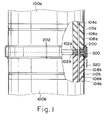
- FIG. 1 is a side view, partly in cross section, of a joint structure for pillars according to the embodiment;
- FIG. 2 is a fragmentary vertical sectional view of a joint structure for pillars according to the embodiment;
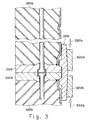
- FIG. 3 is a fragmentary vertical view of a joint structure for pillars according to the embodiment;
- FIG. 4 is a fragmentary vertical sectional view of a joint structure for pillars according to the embodiment;
- FIG. 5 is a fragmentary vertical sectional view of a joint structure for pillars according to the embodiment;
- FIG. 6 is a vertical sectional view of a joint structure for pillars according to the embodiment;
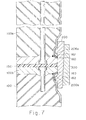
- FIG. 7 is a vertical sectional view of a joint structure for pillars according to the embodiment;
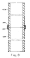
- FIG. 8 is a vertical sectional view of a joint structure for pillars according to the embodiment;
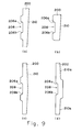
- FIG. 9 shows sectional profiles of examples of inside rings according to the embodiment;
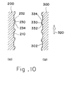
- FIG. 10 is a fragmentary vertical sectional view showing inside rings and outside rings according to the embodiment;
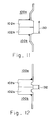
- FIG. 11 shows a sectional profile of a joint end plate according to the embodiment;
- FIG. 12 shows a sectional profile of a joint end plate according to the comparative example;
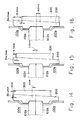
- FIG. 13 is an explanatory view showing the relationship between the manufacturing allowance and the outside ring fitting position;
- FIG. 14 is an explanatory view showing the relationship between the manufacturing allowance and the outside ring fitting position;
- FIG. 15 is an explanatory view showing the relationship between the manufacturing allowance and the outside ring fitting position;
- FIG. 16 is an explanatory view showing the relationship between the manufacturing allowance and the outside ring fitting position; and
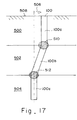
- FIG. 17 is an explanatory view of a mechanism that the ground moves sideward.
-
- FIG. 1 is a side view, partly in cross section, of a joint structure for pillars to which the present invention is applied. FIG. 2 is a fragmentary enlarged vertical view of FIG. 1. An
upper pillar 100a is formed of a precast concrete in which one end of aPC steel bar 104a is fixed on anend plate 102 at the lower end of theupper pillar 100a and pre-stress is applied to a concrete 106a. Theend plate 102a is provided with a truncatedconical seat 122a around the outer periphery on the counter-butted surface. The truncatedconical seat 122a has a surface finished with high accuracy, and which abuts on aside surface 206a of a circumferential recessedgroove 208 having a truncated conical section and provided on the inner surface of aninside ring 200 to be externally fitted around theseat 122a. Anend plate 102b at the upper end of alower pillar 100b is contacted with theend plate 102a at the lower end of thepillar 100a by way ofabutment surfaces end plate 102b is provided with a truncatedconical seat 122b around the outer periphery on the counter-butted surface. The truncatedconical seat 122b abuts on aside surface 206b of the circumferential recessedgroove 208 of theinside ring 200. - The
inside ring 200 is formed into a cylindrical shape and is divided into a plurality of parts in the circumferential direction. Theinside ring 200 is externally fitted around theend plates groove 208 having the truncated conical section and provided on the inner surface of theinside ring 200 abut on theend plates end plates pillars inside ring 200, the circumferential recessedgroove 208 has theside surfaces conical seats outside diameter surface 210 of theinside ring 200 is provided with a conical taper having a gradient in the longitudinal direction of the pillar. - An
outside ring 300 is formed of an integral cylindrical shape having a conical taper along the inner periphery which is externally fitted around the conical taper provided on the outside diameter surface of theinside ring 200. By moving theoutside ring 300 with a specified thrust applied in the longitudinal direction of the pillar shown by thearrow 320, theinside ring 200 constituted of the multi-divided cylindrical ring is fastened by the engagement between the conical taper on the outside diameter surface of theinside ring 200 and the conical taper on the inner diameter surface of theoutside ring 300. The side surfaces 206a and 206b of the circumferential recessedgroove 208 provided on the inner surface of theinside ring 200 abut on the truncatedconical seats end plates end plates pillars - The dimensions of the
inside ring 200 is determined such that a plurality ofmating portions 202 divided in the circumferential direction are slightly spaced apart from each other when thepillars - In this embodiment, the gradient of the cylinder taper for fitting the inside ring to the outside ring is taken as 1/20. On the contact surfaces of the
taper 210 on the outer surface of theinside ring 200 and thetaper 302 on the inner surface of theoutside ring 300, there are formed circumferential sawtooth projections to be meshed with each other. The circumferential projections serve to prevent the movement of the tapers in the loosening direction. - Covering
metal cylinders 108a and 108b are mounted on theend plates portions 112a and 112b are formed in the vicinity of theend plates anchors concretes - In this embodiment, only the truncated conical seats on the end plates of the pillars are finished and others parts are arbitrarily formed into shapes not interfering with each other, and the outside ring is fastened with a specified axial thrust. This simplifies the joint for pillars, which enables the stable joining work for pillars even at the job site. In addition, by coating an inhibitor on the fitting surfaces of the joint for preventing the joint portion in the ground from being damaged in its properties due to rust, the durability of the joint can be enhanced.
- FIG. 3 shows an embodiment applicable for large diameter pillars, wherein a conical taper portion formed on the outside diameter surface of an
inside ring 200 is of a double-structure, which is composed of both tapers provided so as to be opposed to each other with respect to the center of the width in the longitudinal direction of the pillar, and twooutside rings - The joint structure includes the divided type cylindrical
inside ring 200 having a plurality of axial conical taper surfaces on the outer surface, and fastening outside rings 300 to be externally fitted around the outer surface tapers of theinside ring 200. The outer surface tapers of theinside ring 200 are tilted reversely to each other in the axial direction, and are identical to each other in shape. The outside rings 300, which are also identical to each other in shape, are externally fitted around theinside ring 200 reversely to each other, and are simultaneously fastened with an equal force. Accordingly, this joint structure is suitable in equalizing the fastening force, in unifying the kinds of manufacturing parts, and in improving the interchangeability. - For pillars having an outside diameter of 600 mm, the projecting height of the outside ring from the surface of the pillars is about 22 mm; but for pillars having an outside diameter of 1000 mm, the projecting height becomes about 45 mm. For this reason, the outside ring is divided into the two
outside rings - In assembly of the joint structure shown in FIG. 3, the outside rings 300a and 300b are simultaneously drawn in the direction of the
arrows inside ring 200 with an equal fastening force. With this joint structure, the weight of the member is suitably adjusted, and the workability can be enhanced. Moreover, this joint structure is suitable in scattering and equalizing the fastening force, in unifying the kinds of manufacturing parts, and in improving the interchangeability. In particular, this joint structure greatly contributes to the extension in the range of the actual applications of the joints for large diameter pillars. - FIG. 9 shows, in (a), (b), (c) and (d), the sectional profiles of embodiments of the inside rings 200. The side surfaces 206a and 206b of the circumferential recessed
groove 208 on the inner surface of theinside ring 200 abut on theend plates pillars inside ring 200 on the inner surface side are not contacted with any one of theend plates plates 108a and 108b. The above non-contact portions are not required to be finished. Accordingly, the inside ring is extremely simply machined, and has the simple shape. Moreover, the end plate surfaces of thepillars - The inside ring and outside ring can be easily formed in shapes having the sectional profiles shown in Fig. 9 by hot-rolling of steel products, without any complicated cutting.
- The
conical taper surface 210 on the outer surface of the inside ring and theconical taper surface 302 on the inner surface of the outside ring may be provided with the circumferential irregularities having sawtooth sections. FIG. 10(a) is an enlarged vertical view showing the portion in the vicinity of the outside diameter surface of theinside ring 200. FIG.10(b) is an enlarged vertical view showing the portion in the vicinity of the inside diameter surface of theoutside ring 300. Aslope surface 234 and anupright surface 232 of thecircumferential projection 230 of theinside ring 200 are provided oppositely of aslope surface 334 and anupright surface 332 of thecircumferential projection 330 of theoutside ring 300, respectively. When theoutside diameter surface 210 of theinside ring 200 is contacted with the innerperipheral surface 302 of theoutside ring 300 and theoutside ring 300 is moved in the direction of thearrow 320 to fasten theinside ring 200 by the engagement between the conical tapers, the sawtooth projections mesh with each other so as to prevent theoutside ring 300 from being moved in the direction where the fastening of the taper surfaces is loosened (opposed to the direction of the arrow 320). Accordingly, the work of preventing the return by spot welding is eliminated after the inside ring and the outside ring are assembled. The concrete dimensions of the sawtooth projections are specified: the pitch is 3 mm and the height of the sawtooth is about 0.7 mm. - Next, an embodiment of joint structure having flexural toughness for pillars will be described.
- As shown in FIG. 17, when a
pillar 100 driven in the ground from theearth surface 508 is liquefied by earthquake and yields thesideward movement 506, destroyedportions liquefied layer 502 and upper and lowernon-liquefied layers - In an embodiment shown in FIG. 4, an
elastic body 150 is held between twoend plates groove 208 on the inner surface of aninside ring 200, aside wall 206 and abottom surface 204 abut on theend plates side wall 206 of the circumferential recessedgroove 208 is equal to or more than the sum of the dimensions of theelastic body 150 and theend plates - According to the present invention, only the outer peripheral surfaces of the end plates of the pillars are finished and the recessed portion of the inside ring which abut on the outer peripheral surfaces of the end plates is slightly larger than the sum of the thicknesses of the end plates; and the other parts may be formed into shapes not interfering with each other. Accordingly, there can be obtained the earthquake-proof joint structure for piles, which is simplified, and which enables the stable fitting with a specified pressure even at the job site.
- The samples of the elastic bodies used for the above structure of the present invention include an elastic material such as natural rubber, synthetic rubber, elastomer or plate spring; an elastic structure such as high pressure pneumatic or fluid spring; an easy-to-deform material such as lead, tin, antimony or alloys thereof; and easy-to-deform material such as metal or plastic, or structure when a large load is applied.
- As the above elastic material, a chloroprene rubber with high attenuation is suitably used. The chloroprene rubber is obtained by substituting the -CH3 radical by the -Cl radical in a polyisoprene rubber, which is suitably used as an earthquake-proof material being excellent in the aging resistance.
- The elastic body may be formed into a disk or ring shape to abut on the end surface of the pillar, with any radial section such as a planar, circular, rectangular, or rhombic shape.
- Recessed grooves on which the elastic body is seated may be provided by suitably machining the butted surfaces of the end plates to abut on the elastic body according to the shape of the elastic body. In this case, the elastic body can be easily positioned, and also can serve as a sealing material.
- An embodiment shown in FIG. 5 will be described below. Only outer
peripheral surfaces end plates bottom surface 204 of a circumferential recessedgroove 208 on the inner surface of aninside ring 200 which is externally fitted around the outerperipheral surfaces end plates side walls conical seats end plates - The joint structure shown in FIG. 5 is not a perfect rigid joint type, wherein the upper and lower pillars are relatively movable. In this embodiment, the outer peripheral surfaces of the end plates abut on the inner surface of the inside ring; and the other parts of the pillars are not contacted with the inside ring and are not required to be finished. The inside ring and the outside ring can be formed into specified sectional shapes by hot rolling, without any complicated machining, thereby lowering the manufacturing cost.
- Preferably, the
seats end plates side walls groove 208 of theinside ring 200 are also formed into the tapers parallel to those of theseats pillars pillars - Since the
pillars upper pillar 102a is applied on thelower pillar 102b. When thepillars bottom portion 204 of the circumferential recessedgroove 208 on the inner surface of theinside ring 200 abuts on theend plates end plates - The clearance between the recessed groove and the end plates is preferably filled with an elastic material such as rubber. And the elastic material may be equally divided in the vertical direction or may be offset on one side in the groove. The elastic material may be deformed while resisting against the external force.
- FIG.6 illustrates an embodiment provided with an
elastastic body 150 held between twoend plates elastic bodies 160 filled in the clearance between theside walls groove 208 on the inner surface of theinside ring 200 and the truncatedconical seats end plates - Further, FIG.7 shows an embodiment which provides an
elastic body 150 held between twoend plates elastic bodies 160 filled in the clearance between theside walls groove 208 on the inner surface of theinside ring 200 and the truncatedconical seats end plates walls inside ring 200 is made larger than the total sum of the thickness of theend plates elastic body 150 andelastic bodies 160. - The structure in FIG.7 provided with
excess clearances 162 may ensure the maximum flexural toughness among the embodiments. - In the joint structure shown in any one of FIGs. 4, 5, 6 and 7 having the above-described construction, when the ground is liquefied by earthquake and is moved sideward, the joint portion can be deformed while resisting against the sideward movement. In this deformation, the outside ring is elastically relaxed, to permit the relative bending of the axes of the upper and lower pillars. The joints having the above construction are provided at a plurality of positions along the pillar, which makes it possible to cope with a large deformation. In addition, the upper and lower pillars are restricted by the circumference recessed groove of the inside ring, and are not released. The joint structure is not a rigid joint type, and acts to assist the bending toughness of the pillars without destruction as in the conventional pillars, and to follow the sideward movement of the ground while keeping the function against the axial force, that is, the supporting force.
- Since the sideward movement of the ground is generated at the interface between the liquefied layer and non-liquefied layer, it is possible to estimate it prior to the construction on the basis of the groundwater level or the N-value distribution of the standard penetration test. Accordingly, the joint structure of the present invention is designed to be positioned at the above interface for absorbing the energy of earthquake by deformation of the joint portion. Moreover, using a plurality of joint structures, it is possible to follow a large deformation. This makes it possible to prevent the damage of pillars by earthquake, and hence to ensure the safety.
- The joint structure for pillars shown in FIGs. 4, 5, 6 and 7 is of a flexurally tough earthquake-proof structure, and is almost the same in cost as the conventional rigid type joint structure, to be thus excellent in economy and practical use.
- Next, the outside diameter of a pillar and the outside diameter of a joint portion will be described. FIG. 5 shows the joint structure wherein the outside diameter of the
end plates pillars inside ring 200 and theoutside ring 300, however, may be projected outward from the outside diameter surface of thepillars - The joint structure may be applied for the case that upper and
lower pillars - FIGs.11 and 12 comparatively show two cases: the outsides of the
end plates end plates end plates end plates thickness 130 near the total thickness of theend plates - Next, the method of joining the pillars using the joint structure according to the present invention and the determination of the dimensions of the inside ring and the outside ring will be described.
- According to the method of joining pillars using the joint structure of the present invention, in the cylindrical
inside ring 200 divided in the circumferential direction having the conical taper in the longitudinal direction of the pillar, which is engaged with the end plates of the pillars, and theoutside ring 300 having the conical taper externally fitted around theinside ring 200, the length of the conical taper of the inside ring is set to be longer than the length of the taper of theoutside ring 300. Thus, the joining between theinside ring 200 and theoutside ring 300 is performed by applying a specified thrust to theoutside ring 300. - In this joining method, since the
inside ring 200 is joined to theoutside ring 300 with a specified thrust applied to theoutside ring 300, it is possible to give a specified hoop tension to theoutside ring 300. In this case, when the manufacturing errors are generated, the relative positions in fitting of theinside ring 200 to theoutside ring 300 is varied. According to the present invention, the taper length of theinside ring 200 has the margin for absorbing these manufacturing errors. - In the basic joint structure of the present invention, the seats of the
inside ring 200 to abut on the truncated conical seats of the end plates finished with high accuracy are taken as the transmission surfaces for drawing and joining the pillars; and the other surfaces on the pillar side are not allowed to be in contact with theinside ring 200 and are not required to be finished. With this arrangement, the joining portion of the pillars is extremely simply machined, and has a simple shape. Moreover, with this structure, the upper and lower pillar end surfaces are closely contacted with each other, so that there is no loss in transmitting the crimping force. The sectional shapes of theinside ring 200 and theoutside ring 300 are formed by hot-rolling, and therefore, the complicated machine finishing after rolling is not required at all. - The determination of the dimensions of the inside ring and the outside ring will be described with reference to FIG. 13.
- The width of the
inside ring 200 in the longitudinal direction of the pillar is determined to be longer than the outside ring such that the lower end of theoutside ring 300 is located upward from the lower end of theinside ring 200 when theoutside ring 300 is externally fitted around theinside ring 200 with the axial thrust of theoutside ring 300. - Of the manufacturing allowable errors for the
end plates inside ring 200, and theoutside ring 300, the outside diameter D1 of the end plate, the plate thickness T of theinside ring 200, and the clearance C of meshing portion between the outside diameter surface of the end plate and the inside diameter of theinside ring 200 are related to the fitting position of theoutside ring 300. The sum of the above dimensions becomes the outside diameter D2 of theinside ring 200. - The outside diameter D2 of the
inside ring 200 is maximized to be (specified value + 1.2 mm) when D2 is (specified value + maximum allowable value), that is, [D1 + (T + C) × 2]. Theinside ring 200 is minimized to be (specified value -0.45 mm) when D1 is (specified value - minimum allowable value), that is, [D1-T × 2]. Moreover, the inside diameter D2 of theoutside ring 300 after fitting is obtained by addition of the circumferential strain amount to the manufacturing dimension, and the upper surface difference Y is determined by subtracting the inside diameter D3 of theoutside ring 300 from the outside diameter D2 of theinside ring 200. Namely, when the width of theoutside ring 300 is W, the thickness is T1 and the minimum inside diameter is Db the following equations can be obtained. - The axial thrust (jacking pressure) of the
outside ring 300 is determined for each diameter of the pillar, and the fastening force is determined such that the hoop tension with the circumferential strain being about 300µ (300 × 10-6) is generated to satisfy the stresses for a long or short period for each case. - FIGs. 14 to 16 show the examples, wherein the cylindrical taper is 1/20 and the manufacturing allowances of the
end plates inside ring 200 are in the range of ± 1.2 mm to -0.45 mm, and further the outside diameter of the pillar is 600 mm. FIG. 14 shows the example that the end plate and theinside ring 200 are minimized, that is, the lower end diameter of theinside ring 200 is Db =-0.45 mm. In this case, the difference between the center positions of theinside ring 200 and theoutside ring 300 in the longitudinal direction is 8 mm, wherein the difference between the positions before and after theoutside ring 300 is fitted is δh = 2 mm. FIG. 15 shows the example that the end plate and the inside ring have the standard dimensions, that is, the lower end diameter of theinside ring 200 is Db = -0 mm. In this case, the difference between the center positions of theinside ring 200 and theoutside ring 300 in the longitudinal direction is 3.5 mm, wherein the difference between the position before and after theoutside ring 300 is fitted is δh = 2 mm. FIG. 16 shows the example that the end plate and theinside ring 200 are maximized, that is, the lower end diameter of theinside ring 200 is Db = + 1.2 mm. In this case, the difference between the center positions of theinside ring 200 and theoutside ring 300 in the longitudinal direction is -8.5 mm, wherein the difference between the positions before and after theoutside ring 300 is fitted is δh = 2 mm. - The axial allowance in the relative positions for the
outside ring 300 and theinside ring 200 is ± 8.5 mm. Accordingly, by setting the width of theinside ring 200 in the longitudinal direction of the pillar to be larger than that of theoutside ring 300 by 20 mm, when theinside ring 200 is joined to theoutside ring 300 with a specified axial thrust, the lower end of theoutside ring 300 is located upward from the lower end of the inner end of theinside ring 200. Moreover, the upper end of theoutside ring 300 is not protruded from the upper end of theinside ring 200. In addition, δh in FIGs. 14 to 16 shows the amount of the positional change before and after theoutside ring 300 is fitted. - In fitting the
outside ring 300 around theinside ring 200 with the specified axial thrust, even in the case that the allowable errors in the manufacturing dimensions of the joint fitting metal are generated, the length of the conical taper of theinside ring 200 is lengthened such that the whole surface of theoutside ring 300 abuts on the outer surface of theinside ring 200, thus accomplishing the joint with the stable hoop tension.
Claims (12)
- A joint structure for pillars (100), comprising:characterised in thatdisk-like or ring-like end plates (102) which are forcibly fixed on the end surfaces of the pillars to be joined to each other, and which are provided with truncated conical seats (122) around the outer peripheral corner portions of the end plates on the counter-butted surface side;a cylindrical inside ring (200) divided in a plurality of parts along the circumference, and an outside diameter surface (210) having a conical taper tilted in the axial direction of the pillars (100), the inside ring being fitted around the outer periphery of the end plates;an outside ring (300) including an inner surface (302) having a conical taper fitted externally around an outside diameter surface (210) of the inside ring for fastening the inside ring;
the inside ring (200) includes an inner surface having a circumferential recessed groove (208) with side walls (206a, 206b) to abut on the seats of the end plates (102) axially butted to each other, and wherein the inner surface (302) of the outside ring (300) and the outer surface (210) of the inside ring (200) are provided with circumferential sawtooth projections (330; 230) to prevent movement of the tapers in the loosening direction. - A joint structure for pillars according to claim 1, wherein the inside ring (200) has a plurality of conical tapers on the outer surface; and the outside ring (300) has a plurality of outside ring parts (300a, 300b) which are each externally fitted around a plurality of the conical tapers of the inside ring.
- A joint structure for pillars according to claim 1 or 2, wherein the inner surface taper of the outside ring (300) has a gradient ranging from 1/10 to 1/30.
- A joint structure for pillars according to any of claims 1 to 3, wherein an elastic body (150) is interposed between the end plates (102) butted; and the inside ring (200) divided into a plurality of parts in the circumferential direction, includes an inner surface having a circumferential recessed groove (208) with a bottom surface to abut on the outer peripheries of the end plates (102) and with side walls (206) to abut on the seats, and an outside diameter portion having a conical taper tilted along the axial direction of the pillars (100), the inside ring (200) being fitted around the outer periphery of the end plates.
- A joint structure for pillars (100), comprising:characterised in thatdisk-like or ring-like end plates (102) which are forcibly fixed on the end surfaces of the pillars to be joined to each other, and which are provided with truncated conical seats (122) around the outer peripheral corner portions of the end plates on the counter-butted surface side;a cylindrical inside ring (200) divided in a plurality of parts along the circumference and fitted around the outer periphery of the end plates (102), and an outside diameter surface (210) having a conical taper tilted in the axial direction of the pillars (100), the inside ring (200) being fitted around the outer periphery of the end plates (102);an outside ring (300) including an inner surface (302) having a conical taper fitted externally around an outside diameter surface (210) of the inside ring (200) for fastening the inside ring;
the inside ring (200) includes an inner surface having a circumferential recessed groove (208) with an interval between the side walls (206) of the circumferential recessed groove being larger than the sum of the thicknesses of the end plates (102). - A joint structure for pillars according to claim 5, wherein an elastic material (150, 160) is interposed in clearances formed between said end plates (102) and said side walls (206) of said circumferential recessed groove (208).
- A joint structure for pillers according to claim 6, wherein the elastic material is one or more selected from a group consisting of natural rubber, synthetic rubber and easy-to-deform metal.
- A joint structure for pillers according to claim 6 or 7, wherein an elastic body (150) is interposed between said end plates (102) butted.
- A joint structure for pillars according to any of claims 4 to 8, wherein said elastic body (150) comprises one or more of kinds of materials selected from a group consisting of natural rubber, synthetic rubber, plate spring, high pressure pneumatic or fluid spring, and easy-to-deform metal.
- A joint structure for pillars according to any of claims 4 to 9, wherein said elastic body (150) is formed into planar, circular, rectangular or rhombic shape in the radial section.
- A joint structure for pillars according to claim 8, wherein the interval between said walls of said circumferential recessed groove (208) is larger than the total sum of the thicknesses of said end plates (102), said elastic body (150) interposed between said end plates, and said elastic materials (160) which are located in clearances formed between said truncated conical seats of said end plates and said walls of said circumferential recessed groove.
- A method of joining pillars (100) to each other, comprising the steps of:characterised in thatjoining a cylindrical inside ring (200) divided into a plurality of parts in the circumferential direction and including an outer surface having a conical taper in the longitudinal direction of end plates (102) of the pillars, the inside ring being engaged with the pillars, to an outside ring (300) having a conical taper fitted externally around the inside ring;wherein the length of the conical taper of the inside ring (200) is longer than the length of the taper of the outside ring (300); and the joining is performed by applying a specified axial thrust to the outside ring,
the inner surface of the outside ring (300) and the outer surface of the inside ring (200) are provided with circumferential sawtooth projections (330; 230) to prevent movement of the tapers in the loosening direction.
Applications Claiming Priority (9)
| Application Number | Priority Date | Filing Date | Title |
|---|---|---|---|
| JP33370393A JP3271725B2 (en) | 1993-12-27 | 1993-12-27 | Connection method of pile |
| JP333702/93 | 1993-12-27 | ||
| JP33370393 | 1993-12-27 | ||
| JP33370493A JPH07189246A (en) | 1993-12-27 | 1993-12-27 | Joint structure of pile |
| JP33370493 | 1993-12-27 | ||
| JP333703/93 | 1993-12-27 | ||
| JP333704/93 | 1993-12-27 | ||
| JP33370293 | 1993-12-27 | ||
| JP33370293A JP3318419B2 (en) | 1993-12-27 | 1993-12-27 | Pile joint structure |
Publications (2)
| Publication Number | Publication Date |
|---|---|
| EP0663476A1 EP0663476A1 (en) | 1995-07-19 |
| EP0663476B1 true EP0663476B1 (en) | 1999-09-08 |
Family
ID=27340620
Family Applications (1)
| Application Number | Title | Priority Date | Filing Date |
|---|---|---|---|
| EP94105382A Expired - Lifetime EP0663476B1 (en) | 1993-12-27 | 1994-04-07 | Joint structure for pillars and its joining method |
Country Status (5)
| Country | Link |
|---|---|
| US (1) | US5577857A (en) |
| EP (1) | EP0663476B1 (en) |
| KR (1) | KR950018957A (en) |
| DE (1) | DE69420541T2 (en) |
| TW (1) | TW274570B (en) |
Families Citing this family (14)
| Publication number | Priority date | Publication date | Assignee | Title |
|---|---|---|---|---|
| DE19837708C2 (en) * | 1998-08-20 | 2002-11-07 | Bilfinger Berger Ag | Device and method for coupling the individual shots of a rod-shaped support member |
| US6996946B1 (en) * | 1999-02-26 | 2006-02-14 | Sergio Cazzolaro | Structures which can be dismantled and folded, consisting of interconnecting tubular elements |
| CN2403821Y (en) * | 2000-01-12 | 2000-11-01 | 钟肇鸿 | Fast connector for steel reinforced concrete precast pile |
| US7204064B2 (en) * | 2000-02-18 | 2007-04-17 | Sergio Cazzolaro | Structures which can be dismantled and folded, consisting of interconnecting tubular elements |
| US7546656B2 (en) * | 2005-08-16 | 2009-06-16 | Daewoo Engineering & Construction Co., Ltd | Method of installing prefabricated, segment concrete filled tube members |
| US9441757B2 (en) | 2005-12-21 | 2016-09-13 | Fisher Controls International Llc | Load relieving stem connectors |
| US8696231B2 (en) * | 2005-12-21 | 2014-04-15 | Fisher Controls International Llc | Load relieving stem connectors |
| US8602123B2 (en) * | 2009-08-18 | 2013-12-10 | Crux Subsurface, Inc. | Spindrill |
| GB2485350A (en) * | 2010-11-08 | 2012-05-16 | Coupling Solutions Llc | Pipe coupling |
| CN102352624A (en) * | 2011-09-26 | 2012-02-15 | 浙江中淳新材料股份有限公司 | Pile splicing structure for precast piles |
| US9828739B2 (en) | 2015-11-04 | 2017-11-28 | Crux Subsurface, Inc. | In-line battered composite foundations |
| CN108474241A (en) * | 2016-03-03 | 2018-08-31 | 哈利伯顿能源服务公司 | Inner cores cylinder for coring tool crimps connection |
| CN106049490B (en) * | 2016-07-18 | 2019-04-30 | 周兆弟 | Hafu-type connector and pile body connection structure |
| US20220049575A1 (en) * | 2020-08-14 | 2022-02-17 | PetroQuip Energy Services, LLC | Shutoff Valve |
Family Cites Families (14)
| Publication number | Priority date | Publication date | Assignee | Title |
|---|---|---|---|---|
| US969943A (en) * | 1909-11-08 | 1910-09-13 | Frederick N Cronholm | Pipe-coupling. |
| US3460300A (en) * | 1963-08-16 | 1969-08-12 | Howlett Machine Works | Concrete prestressing apparatus (tank) |
| US3931716A (en) * | 1974-06-07 | 1976-01-13 | Donald Payne | Pile splice for concrete and steel piles of various configuration |
| US4159132A (en) * | 1978-04-03 | 1979-06-26 | Hitz Gifford L | Sealed connection |
| FR2519673A1 (en) * | 1982-01-11 | 1983-07-18 | Freyssinet Int Stup | EXTENDED CONCRETE ELEMENTS PRECONTRAINT, ASSEMBLABLES END TO END |
| JPS59126820A (en) * | 1983-01-11 | 1984-07-21 | Ube Ind Ltd | Connection structure of concrete foundation pile |
| US5012622A (en) * | 1985-03-05 | 1991-05-07 | Shimizu Construction Co., Ltd. | Structural filler filled steel tube column |
| JPS61204418A (en) * | 1985-03-08 | 1986-09-10 | Kisho Takagi | Small sized reinforced concrete pile |
| US4684156A (en) * | 1986-07-30 | 1987-08-04 | The United States Of America As Represented By The Administrator Of The National Aeronautics And Space Administration | Preloaded space structural coupling joint |
| US5232249A (en) * | 1987-05-27 | 1993-08-03 | Harald Kolvereid | Fastening device |
| DE3834266A1 (en) * | 1988-10-08 | 1990-04-12 | Dyckerhoff & Widmann Ag | DEVICE FOR ANCHORING A ROD-SHAPED TENSION LINK MADE OF FIBER COMPOSITE MATERIAL |
| JPH0383224A (en) * | 1989-08-25 | 1991-04-09 | Nec Corp | Magnetic disk |
| DE4009403C2 (en) * | 1990-03-23 | 1995-07-27 | Schott Glaswerke | Pipe coupling |
| ES2083721T3 (en) * | 1991-07-04 | 1996-04-16 | Vsl Int Ag | DEVICE FOR THE JOINT OF TWO WRAPPING TUBES. |
-
1994
- 1994-04-07 EP EP94105382A patent/EP0663476B1/en not_active Expired - Lifetime
- 1994-04-07 US US08/224,573 patent/US5577857A/en not_active Expired - Fee Related
- 1994-04-07 DE DE69420541T patent/DE69420541T2/en not_active Expired - Fee Related
- 1994-04-11 TW TW083103181A patent/TW274570B/zh not_active IP Right Cessation
- 1994-04-21 KR KR1019940008391A patent/KR950018957A/en not_active IP Right Cessation
Also Published As
| Publication number | Publication date |
|---|---|
| DE69420541D1 (en) | 1999-10-14 |
| EP0663476A1 (en) | 1995-07-19 |
| KR950018957A (en) | 1995-07-22 |
| US5577857A (en) | 1996-11-26 |
| DE69420541T2 (en) | 1999-12-23 |
| TW274570B (en) | 1996-04-21 |
Similar Documents
| Publication | Publication Date | Title |
|---|---|---|
| EP0663476B1 (en) | Joint structure for pillars and its joining method | |
| US6474030B1 (en) | Pile foundation structure | |
| JP2664653B2 (en) | Pile joint structure | |
| EP0214800B1 (en) | Filler filled steel tube column | |
| US20040047693A1 (en) | Joining structure of pile | |
| IE822730L (en) | Hollow structures and method for their production | |
| JP3741426B2 (en) | Pile head and structure joining apparatus and installation method thereof | |
| US5127680A (en) | Pipe joint structure | |
| CN210482321U (en) | Foundation pit support | |
| US4838736A (en) | Resilient bush | |
| JP7390924B2 (en) | Liner plate connection method and fastening fittings | |
| JPH07189246A (en) | Joint structure of pile | |
| JP2579499B2 (en) | Repair method of horseshoe-shaped existing tunnel lining | |
| EP1010815B1 (en) | Splice for a drilled pile | |
| JPS59228521A (en) | Landslide preventive pile | |
| JP2021031926A (en) | Steel structure pile/column joint integrated column base structure without underground beam | |
| JPH0784840B2 (en) | Steel segment and tunnel construction method using steel segment | |
| CN212452613U (en) | Pile body angle bead cover and prefabricated building structure | |
| CN213038415U (en) | Building earthwork pile foundation structure | |
| Knoedel | Cylinder-cone-cylinder intersections under axial compression | |
| CN212865923U (en) | Anticorrosion tubular pile for foundation | |
| JPH09273171A (en) | Differential settlement correction method of pile | |
| JP2572753Y2 (en) | Pile-free joint structure | |
| JPH07259082A (en) | Joint structure of column | |
| JP2613640B2 (en) | Joint method of steel pipe pile |
Legal Events
| Date | Code | Title | Description |
|---|---|---|---|
| PUAI | Public reference made under article 153(3) epc to a published international application that has entered the european phase |
Free format text: ORIGINAL CODE: 0009012 |
|
| AK | Designated contracting states |
Kind code of ref document: A1 Designated state(s): DE FR GB |
|
| 17P | Request for examination filed |
Effective date: 19950807 |
|
| 17Q | First examination report despatched |
Effective date: 19960215 |
|
| GRAG | Despatch of communication of intention to grant |
Free format text: ORIGINAL CODE: EPIDOS AGRA |
|
| GRAG | Despatch of communication of intention to grant |
Free format text: ORIGINAL CODE: EPIDOS AGRA |
|
| GRAH | Despatch of communication of intention to grant a patent |
Free format text: ORIGINAL CODE: EPIDOS IGRA |
|
| GRAH | Despatch of communication of intention to grant a patent |
Free format text: ORIGINAL CODE: EPIDOS IGRA |
|
| GRAA | (expected) grant |
Free format text: ORIGINAL CODE: 0009210 |
|
| AK | Designated contracting states |
Kind code of ref document: B1 Designated state(s): DE FR GB |
|
| REF | Corresponds to: |
Ref document number: 69420541 Country of ref document: DE Date of ref document: 19991014 |
|
| ET | Fr: translation filed | ||
| PLBE | No opposition filed within time limit |
Free format text: ORIGINAL CODE: 0009261 |
|
| STAA | Information on the status of an ep patent application or granted ep patent |
Free format text: STATUS: NO OPPOSITION FILED WITHIN TIME LIMIT |
|
| 26N | No opposition filed | ||
| REG | Reference to a national code |
Ref country code: GB Ref legal event code: IF02 |
|
| PGFP | Annual fee paid to national office [announced via postgrant information from national office to epo] |
Ref country code: FR Payment date: 20020313 Year of fee payment: 9 |
|
| PGFP | Annual fee paid to national office [announced via postgrant information from national office to epo] |
Ref country code: GB Payment date: 20020402 Year of fee payment: 9 |
|
| PGFP | Annual fee paid to national office [announced via postgrant information from national office to epo] |
Ref country code: DE Payment date: 20020410 Year of fee payment: 9 |
|
| PG25 | Lapsed in a contracting state [announced via postgrant information from national office to epo] |
Ref country code: GB Free format text: LAPSE BECAUSE OF NON-PAYMENT OF DUE FEES Effective date: 20030407 |
|
| PG25 | Lapsed in a contracting state [announced via postgrant information from national office to epo] |
Ref country code: DE Free format text: LAPSE BECAUSE OF NON-PAYMENT OF DUE FEES Effective date: 20031101 |
|
| GBPC | Gb: european patent ceased through non-payment of renewal fee |
Effective date: 20030407 |
|
| PG25 | Lapsed in a contracting state [announced via postgrant information from national office to epo] |
Ref country code: FR Free format text: LAPSE BECAUSE OF NON-PAYMENT OF DUE FEES Effective date: 20031231 |
|
| REG | Reference to a national code |
Ref country code: FR Ref legal event code: ST |