EP0663051B1 - Raccord tournant pour tubes a bouts plans - Google Patents
Raccord tournant pour tubes a bouts plans Download PDFInfo
- Publication number
- EP0663051B1 EP0663051B1 EP92921050A EP92921050A EP0663051B1 EP 0663051 B1 EP0663051 B1 EP 0663051B1 EP 92921050 A EP92921050 A EP 92921050A EP 92921050 A EP92921050 A EP 92921050A EP 0663051 B1 EP0663051 B1 EP 0663051B1
- Authority
- EP
- European Patent Office
- Prior art keywords
- retainer means
- retainer
- connector assembly
- conduit
- assembly according
- Prior art date
- Legal status (The legal status is an assumption and is not a legal conclusion. Google has not performed a legal analysis and makes no representation as to the accuracy of the status listed.)
- Expired - Lifetime
Links
Images
Classifications
-
- F—MECHANICAL ENGINEERING; LIGHTING; HEATING; WEAPONS; BLASTING
- F16—ENGINEERING ELEMENTS AND UNITS; GENERAL MEASURES FOR PRODUCING AND MAINTAINING EFFECTIVE FUNCTIONING OF MACHINES OR INSTALLATIONS; THERMAL INSULATION IN GENERAL
- F16L—PIPES; JOINTS OR FITTINGS FOR PIPES; SUPPORTS FOR PIPES, CABLES OR PROTECTIVE TUBING; MEANS FOR THERMAL INSULATION IN GENERAL
- F16L27/00—Adjustable joints, Joints allowing movement
- F16L27/08—Adjustable joints, Joints allowing movement allowing adjustment or movement only about the axis of one pipe
- F16L27/0804—Adjustable joints, Joints allowing movement allowing adjustment or movement only about the axis of one pipe the fluid passing axially from one joint element to another
- F16L27/0808—Adjustable joints, Joints allowing movement allowing adjustment or movement only about the axis of one pipe the fluid passing axially from one joint element to another the joint elements extending coaxially for some distance from their point of separation
- F16L27/0812—Adjustable joints, Joints allowing movement allowing adjustment or movement only about the axis of one pipe the fluid passing axially from one joint element to another the joint elements extending coaxially for some distance from their point of separation with slide bearings
- F16L27/0816—Adjustable joints, Joints allowing movement allowing adjustment or movement only about the axis of one pipe the fluid passing axially from one joint element to another the joint elements extending coaxially for some distance from their point of separation with slide bearings having radial sealing
-
- F—MECHANICAL ENGINEERING; LIGHTING; HEATING; WEAPONS; BLASTING
- F16—ENGINEERING ELEMENTS AND UNITS; GENERAL MEASURES FOR PRODUCING AND MAINTAINING EFFECTIVE FUNCTIONING OF MACHINES OR INSTALLATIONS; THERMAL INSULATION IN GENERAL
- F16L—PIPES; JOINTS OR FITTINGS FOR PIPES; SUPPORTS FOR PIPES, CABLES OR PROTECTIVE TUBING; MEANS FOR THERMAL INSULATION IN GENERAL
- F16L33/00—Arrangements for connecting hoses to rigid members; Rigid hose connectors, i.e. single members engaging both hoses
Definitions
- the present invention relates to connectors for plain end tubing, and more particularly, to a swivelable connector assembly for adjoining a plain end tube to another conduit.
- US-A-4 969 668 discloses a connector assembly for use with a plane end flexible conduit and which has a tubular conduit with an axial bore and an external surface which includes an annular projection, a first tubular retainer means having first and second ends and an axial bore therethrough, said retainer means further includes an incurved annular flange portion for supporting the first retainer means on the external surface of the tubular conduit, a sealing element is disposed on the external surface of the tubular conduit and engages the first retainer means and a second retainer means is provided for securing the flexible conduit over the first retaining means.
- Another object of the present invention is to provide a connector assembly wherein both highly flexible and moderately flexible hose can be utilized.
- the present invention provides a connector assembly for use with a plane end flexible conduit and comprising: a tubular conduit with an axial bore and an external surface which includes an annular projection; first tubular retainer means having an axial bore in which said tubular conduit is received, first and second ends and an incurved annular flange portion for engaging the external surface of the tubular conduit for supporting the first retainer means on said tubular conduit; a sealing element disposed on the external surface of the tubular conduit; and second retainer means for securing the flexible conduit over the first retainer mean; characterised in that said first retainer means is swivelable on the conduit, in that the first retainer means has a second in-turned annular flange portion which engages the external surface of the tubular conduit; in that said sealing element is in contact with both the tubular conduit and the flexible conduit and in that said sealing element is located between an end of said first retainer means and said annular projection.
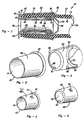
- the connector assembly 10 includes a plain end hose or flexible conduit 12, a tubular conduit 22, an retainer 34, a rotating inner retainer 48 and sealing means 70.
- the tubular conduit 22 is formed with an annular projection 28 disposed a pre-determined distance from a first end 24.
- the annular projection 28 occurs proximate to the leading end of the conduit, however, it is contemplated that other diameters of conduit 22 may be provided at various locations along the tubular conduit, and that the conduit 22 may have enlarged diameter portions (not shown) other than the projection 28 at various longitudinal positions thereon.
- the retainer 34 is adapted to be disposed over the outer surface 14 of the plain end hose 12.
- the retainer 34 has an outwardly projecting leading end 40 to facilitate the insertion of the leading end 18 of the hose 12.
- the retainer 34 tapers slightly downwardly from the leading end 40 toward the trailing end 42 such that the diameter of the retainer 34 is greater at the leading end 40 than it is at the trailing end 42.
- the rotating inner retainer 48 is adapted to be disposed generally within the axial bore 20 of the plain end hose 12.
- the rotating inner retainer includes at the leading end 56, a first incurved flange portion 58, and at the trailing end 62, a second incurved flange portion 64.
- This rotating inner retainer 48 also tapers downwardly from the leading end 56 toward the trailing end 62 such that the diameter of the inner retainer 48 is greater at the leading end 56 then it is at the trailing end 62.
- the rotating inner retainer 48 and the elastomeric O-shaped sealing ring O-ring 70 are positioned over the tubular conduit 22 such that the sealing ring 70 is disposed between the leading end 56 of the inner retainer 48 and the annular projection 28 of the tubular conduit 22 and provides a fluid tight rotating seal between the I.D. of the hose 12 and the O.D. of the conduit 22.
- the retainer 34 is positioned over the plain end hose 12.
- the leading end 18 of the hose 12 is inserted into the outwardly projecting leading end 40 of the retainer and the hose is advanced through the retainer's axial bore 46 such that the leading end 18 of the hose extends beyond the trailing end 42 of the retainer. With the retainer intact, the hose 12 is then positioned over the tubular conduit 22, rotating inner retainer 48 and sealing ring 70. The leading end 18 of the hose 12 is pushed over the annular projection 28 of the tubular conduit 22 and further advanced until the inner surface 16 of the hose 12 substantially overlaps the outer surface 50 of the inner retainer 48. This, in turn, causes sealing ring 70 to become entrapped between the annular projection 28 of the tubular conduit 22 and the leading end 56 of the inner retainer 48. Sealing ring 70 serves the additional function of retaining the inner retainer 48 upon the tubular conduit 22 prior to connecting the hose 12 and outer sleeve 34 over the inner sleeve 48, sealing ring 70 and tubular conduit 22.
- the retainer 34 is moved back upon the outer surface 14 of the hose 12 in the direction of the leading end 18 to lock the hose in position over the tubular conduit 22, inner retainer 48 and sealing ring 70.
- the downward tapering of both the inner retainer 48 and the retainer 34 from the leading end to the trailing end causes the leading end 18 of the hose 12 to become pinched and secured in placed by the inner surface 36 of the retainer 34 and the outer surface 50 of the inner retainer 48.
- the taper angles of the retainers 34 and 48 may be the same or slightly different and may be beneficially designed in the manner disclosed in the applicant's United States Patent No.
- the connector assembly 10 can now be swivelably rotated without the hose becoming twisted as would be the case with non-rotating connector assemblies. Edges 60 and 66 of the first and second incurved flange portions 58 and 64, respectively, ride upon the outer surface 32 of the tubular conduit 22 as the inner retainer 48, plain end hose 12 and retainer 34 swivel and move in unison when the hose is rotated. Fluids can now be transferred from the axial bore 30 of the tubular conduit to the axial bore 20 of the hose 12. It is contemplated that the inner retainer 48 could be made of or coated with a material which provides a low amount of friction. Certain plastics such as polyethylene or other low friction materials such as teflon would be particularly useful.
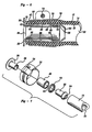
- FIG. 6 a second embodiment of a swivelable connector assembly of the present invention is disclosed.
- the connector assembly of Figure 6 is essentially the same as that of Figure 1 except that the retainer 34 of the embodiment shown in Figure 1 is replaced by a screw-type hose clamp 72 in the embodiment of Figures 6 and 7. Therefore, identical reference numerals are used to describe identical features.
- the inner rotating retainer 48 and the sealing ring 70 are positioned on the tubular conduit 22.
- the clamp 72 is then loosely positioned over the outer surface 14 of the plain end hose 12.
- the hose 12 is advanced over the tubular conduit 22, rotating inner retainer 48 and sealing ring 70 until the leading end 18 of the hose 12 extends past the trailing end 62 of the inner retainer 48.
- the clamp 72 is then aligned over the outer surface 14 of the hose at a point located between the annular projection 28 and the trailing end 26 of the tubular conduit 22.
- Clamp screw 74 is then rotated to reduce the diameter of the band 76 to the point that the inner surface 78 of the band compresses the hose against the outer surface 50 of the rotating inner retainer 48.
- the angle of taper of the clamp 72 and inner retainer 48 may be the same or slightly different, pursuant to U.S. Patent No. 4,923,226.
- FIG. 4 a slightly modified form of the invention shown in Figure 1 is disclosed wherein the retainers 34' and 48' have been modified to include radially projecting tabs 44 and 54, respectfully, which assist in further locking the retainer to the hose.
- the rotating inner retainer 48' includes at least one outwardly projecting tab member 54 which extends outwardly from outer surface 50 to further depress a portion of the inner surface 16 of hose 12.
- the retainer 34' is provided with at least one tab member 44 which projects inwardly from the inner surface 36 to further depress a portion of the outer surface 14 of hose 12 upon assembly of the hose 12 between the retainers 34', 48'.
Landscapes
- Engineering & Computer Science (AREA)
- General Engineering & Computer Science (AREA)
- Mechanical Engineering (AREA)
- Quick-Acting Or Multi-Walled Pipe Joints (AREA)
- Joints Allowing Movement (AREA)
Claims (10)
- Ensemble de raccord destiné à être utilisé avec un conduit souple à extrémité plane (12) et comprenant :caractérisé en ce que le premier dispositif à organe de retenue (48) peut pivoter sur un conduit tubulaire (22), en ce que le premier dispositif à organe de retenue (48) a une seconde partie de bride annulaire (64) retournée vers l'intérieur et qui coopère avec la surface externe du conduit tubulaire (22), en ce que l'élément d'étanchéité (70) peut être mis au contact à la fois du conduit tubulaire (22) et du conduit souple (12), et en ce que l'élément d'étanchéité (70) est placé entre une extrémité (56) du premier dispositif à organe de retenue et la saillie annulaire (28).un conduit tubulaire (22) ayant un trou axial et une surface externe qui a une saillie annulaire (28), un premier dispositif à organe tubulaire de retenue (48) ayant un trou axial dans lequel est logé le conduit tubulaire (22),une première et une seconde extrémité (56, 62) et une partie annulaire (58) de bride recourbée vers l'intérieur et destinée à coopérer avec la surface externe du conduit tubulaire pour le support du premier dispositif à organe de retenue placé sur le conduit tubulaire,le premier dispositif à organe de retenue (48) pouvant être logé dans le conduit souple (12),un élément d'étanchéité (70) placé à une surface externe du conduit tubulaire (22), etun second dispositif à organe de retenue (34) destiné à fixer le conduit souple (12) sur le premier dispositif à organe de retenue (48),
- Ensemble de raccord selon la revendication 1, caractérisé en ce que le second dispositif à organe de retenue (34) comporte un manchon cylindrique effilé (38) ayant une première et une seconde extrémité (40, 42) et un trou axial entre elles, la première extrémité (40) ayant une partie recourbée vers l'extérieur est destinée à faciliter le logement du conduit souple à extrémité plane.
- Ensemble de raccord selon la revendication 2, caractérisé en ce que le manchon (38) du second dispositif à organe de retenue (34) a une dimension qui diminue progressivement vers l'intérieur de la première extrémité (40) vers la seconde extrémité (42).
- Ensemble de raccord selon la revendication 1, caractérisé en ce que le second dispositif à organe de retenue comporte une bande circonférentielle (72) comportant un dispositif (74) destiné à augmenter et réduire le diamètre total de la bande.
- Ensemble de raccord selon l'une quelconque des revendications précédentes, caractérisé en ce que le premier dispositif tubulaire à organe de retenue (48) a une dimension qui diminue vers l'intérieur de la première extrémité (56) vers la seconde extrémité (62).
- Ensemble de raccord selon les revendications 3 et 5, caractérisé en ce que le premier dispositif à organe de retenue a une dimension qui diminue progressivement avec un angle de variation différent de celui du second dispositif à organe de retenue.
- Ensemble de raccord selon l'une quelconque des revendications précédentes, caractérisé en ce que la première bride annulaire (58) est disposée à proximité de la première extrémité (56) du premier dispositif à organe de retenue (48) et la seconde bride annulaire (64) est placée à proximité de la seconde extrémité (62) du premier dispositif à organe de retenue.
- Ensemble de raccord selon l'une quelconque des revendications précédentes, caractérisé en ce que le premier dispositif à organe de retenue (48') a au moins une patte (54) qui dépasse vers l'extérieur et qui accroít la retenue du conduit souple (12).
- Ensemble de raccord selon l'une quelconque des revendications précédentes, caractérisé en ce que le second dispositif à organe de retenue (34') comporte au moins une patte (44) qui dépasse vers l'intérieur et qui accroít la retenue du conduit souple.
- Ensemble de raccord selon l'une quelconque des revendications précédentes, caractérisé en ce que l'élément d'étanchéité (70) est un joint torique.
Applications Claiming Priority (1)
| Application Number | Priority Date | Filing Date | Title |
|---|---|---|---|
| PCT/US1992/007998 WO1994007075A1 (fr) | 1992-09-21 | 1992-09-21 | Raccord tournant pour tubes a bouts plans |
Publications (3)
| Publication Number | Publication Date |
|---|---|
| EP0663051A1 EP0663051A1 (fr) | 1995-07-19 |
| EP0663051A4 EP0663051A4 (fr) | 1995-08-09 |
| EP0663051B1 true EP0663051B1 (fr) | 1998-08-12 |
Family
ID=22231392
Family Applications (1)
| Application Number | Title | Priority Date | Filing Date |
|---|---|---|---|
| EP92921050A Expired - Lifetime EP0663051B1 (fr) | 1992-09-21 | 1992-09-21 | Raccord tournant pour tubes a bouts plans |
Country Status (8)
| Country | Link |
|---|---|
| US (1) | US5582437A (fr) |
| EP (1) | EP0663051B1 (fr) |
| JP (1) | JPH08501377A (fr) |
| AU (1) | AU677572B2 (fr) |
| CA (1) | CA2143214A1 (fr) |
| CZ (1) | CZ68895A3 (fr) |
| DE (1) | DE69226657T2 (fr) |
| WO (1) | WO1994007075A1 (fr) |
Families Citing this family (12)
| Publication number | Priority date | Publication date | Assignee | Title |
|---|---|---|---|---|
| US5611576A (en) * | 1995-11-24 | 1997-03-18 | Industrie Borla Spa | Female coupling element for haemodialysis medical equipment |
| US6098346A (en) * | 1997-12-01 | 2000-08-08 | Newmar Corporation | Slide out kitchen for motor homes and the like |
| GB9912120D0 (en) * | 1999-05-26 | 1999-07-28 | Mckechnie Uk Ltd | Improvements in or relating to pipe joints |
| US6374806B1 (en) * | 1999-10-25 | 2002-04-23 | International Truck And Engine Corp. | Actuating fluid delivery system for a fuel injector |
| WO2003012329A1 (fr) * | 2001-07-25 | 2003-02-13 | Itr S.P.A. | Element rapporte pour raccord hydraulique et raccord hydraulique comprenant un tel element rapporte |
| JP2007016990A (ja) * | 2005-06-08 | 2007-01-25 | Tokai Rubber Ind Ltd | ホースクランプの保持構造 |
| US7806442B2 (en) * | 2006-03-03 | 2010-10-05 | Parker-Hannifin Corporation | Hose coupling with molded seal insert |
| DE202006008069U1 (de) * | 2006-05-19 | 2006-07-20 | Ipa Produktions- & Vertriebsges.M.B.H. | Verbindungseinrichtung für Verbundrohre und Kunststoffrohre sowie entsprechende Anordnung |
| IL177035A (en) * | 2006-07-23 | 2010-11-30 | Sagiv Agudah Shitufit Chaklait Be Am | Pipe fitting assembly and a method for forming it |
| US20080098989A1 (en) * | 2006-10-31 | 2008-05-01 | Caterpillar Inc. | Fuel-injection system |
| JP5579485B2 (ja) * | 2010-04-09 | 2014-08-27 | 株式会社三栄水栓製作所 | 管継手 |
| US10907587B2 (en) * | 2014-04-30 | 2021-02-02 | Abc Technologies Inc. | Air duct with in-molded anti-crush ring |
Family Cites Families (17)
| Publication number | Priority date | Publication date | Assignee | Title |
|---|---|---|---|---|
| US1657987A (en) * | 1923-08-20 | 1928-01-31 | John A Albertoni | Swinging joint |
| US1802572A (en) * | 1928-10-01 | 1931-04-28 | Walter E Phillips | Coupling |
| NL27183C (fr) * | 1930-01-04 | |||
| US2501619A (en) * | 1947-04-26 | 1950-03-21 | Schulthess Ernest | Hose coupling |
| US2764430A (en) * | 1953-07-17 | 1956-09-25 | Maeward Couplings Inc | Swivel coupling for tubing and hose |
| US2825588A (en) * | 1955-05-18 | 1958-03-04 | Scovill Manufacturing Co | Flexible hose coupling having strengthening means |
| US3262718A (en) * | 1965-04-14 | 1966-07-26 | Donald A Draudt | Swivel coupling for coupling flexible and rigid tubular members in end to end relationship |
| US3367681A (en) * | 1965-10-11 | 1968-02-06 | Screw Machine Products Co | Swivel fitting |
| US3957293A (en) * | 1974-04-01 | 1976-05-18 | Nycoil Company | Air hose |
| US4225162A (en) * | 1978-09-20 | 1980-09-30 | Amp Incorporated | Liquid tight connector |
| US4412693A (en) * | 1981-07-31 | 1983-11-01 | Sergio Campanini | Swivel hose coupling with threaded nipple |
| DE3136018C1 (de) * | 1981-09-11 | 1983-02-03 | Rasmussen Gmbh, 6457 Maintal | Vorrichtung zum Befestigen eines Schlauches auf einem Rohrstutzen |
| US4676241A (en) * | 1984-01-16 | 1987-06-30 | W.L.G. Technology | Ventilation tube swivel |
| US4923226A (en) * | 1987-06-23 | 1990-05-08 | Proprietary Technology, Inc. | Apparatus for attaching a hose to a fitting |
| JPH0633844B2 (ja) * | 1987-09-29 | 1994-05-02 | ブリヂストンフロ−テック株式会社 | 管継手 |
| DE3815167C1 (fr) * | 1988-05-04 | 1989-09-14 | Rasmussen Gmbh, 6457 Maintal, De | |
| US5051539A (en) * | 1990-06-07 | 1991-09-24 | Dave A. Leathers | Swivel joint for cover of fluid-cooled welding cable |
-
1992
- 1992-09-21 JP JP6508030A patent/JPH08501377A/ja active Pending
- 1992-09-21 DE DE69226657T patent/DE69226657T2/de not_active Expired - Fee Related
- 1992-09-21 AU AU26700/92A patent/AU677572B2/en not_active Ceased
- 1992-09-21 WO PCT/US1992/007998 patent/WO1994007075A1/fr active IP Right Grant
- 1992-09-21 EP EP92921050A patent/EP0663051B1/fr not_active Expired - Lifetime
- 1992-09-21 US US08/403,881 patent/US5582437A/en not_active Expired - Fee Related
- 1992-09-21 CA CA002143214A patent/CA2143214A1/fr not_active Abandoned
- 1992-09-21 CZ CZ95688A patent/CZ68895A3/cs unknown
Also Published As
| Publication number | Publication date |
|---|---|
| CZ68895A3 (en) | 1995-11-15 |
| DE69226657T2 (de) | 1999-04-15 |
| CA2143214A1 (fr) | 1994-03-31 |
| EP0663051A4 (fr) | 1995-08-09 |
| US5582437A (en) | 1996-12-10 |
| AU677572B2 (en) | 1997-05-01 |
| WO1994007075A1 (fr) | 1994-03-31 |
| AU2670092A (en) | 1994-04-12 |
| JPH08501377A (ja) | 1996-02-13 |
| EP0663051A1 (fr) | 1995-07-19 |
| DE69226657D1 (de) | 1998-09-17 |
Similar Documents
| Publication | Publication Date | Title |
|---|---|---|
| US4871196A (en) | Double shield fitting | |
| US4630848A (en) | Releasable coupling for tubes or pipes | |
| US5350200A (en) | Tube coupling assembly | |
| EP0663051B1 (fr) | Raccord tournant pour tubes a bouts plans | |
| US6086118A (en) | Quick connect tubing connector | |
| US5803512A (en) | Tube quick connect to female socket | |
| US5538297A (en) | Quick connect tubing connector | |
| US4932686A (en) | Telescoping connector for a fluid coupling assembly | |
| US7370889B2 (en) | Tube connector | |
| US4422675A (en) | Co-axial tube coupling | |
| EP1262702A1 (fr) | Procédé et structure pour empêcher le glissement d'un tuyau d'un raccord de tuyaux en plastique | |
| US9371945B2 (en) | Corrugated tube connector | |
| AU6761694A (en) | Quick-action coupling for pipes or hoses | |
| EP0531068A2 (fr) | Raccord de tuyaux | |
| US3618990A (en) | Tube coupling | |
| US5076616A (en) | Hydraulic fitting with O-ring seal end stop | |
| EP0995937A2 (fr) | Dispositif d'accouplement pour fluides avec filetages échelonnés et synchronisés | |
| EP1859188A1 (fr) | Partie de connecteur | |
| GB2274696A (en) | Swivel type hose end fitting | |
| EP1441167B1 (fr) | Raccord | |
| JP2561694B2 (ja) | 管継手 | |
| EP1215434B1 (fr) | Connexion sécurisée pour des systèmes de fluides | |
| GB2151323A (en) | Improvements in or relating to hose couplings | |
| EP0036254A1 (fr) | Raccord de tuyau | |
| AU731246B2 (en) | Hose fitting |
Legal Events
| Date | Code | Title | Description |
|---|---|---|---|
| PUAI | Public reference made under article 153(3) epc to a published international application that has entered the european phase |
Free format text: ORIGINAL CODE: 0009012 |
|
| 17P | Request for examination filed |
Effective date: 19950309 |
|
| AK | Designated contracting states |
Kind code of ref document: A1 Designated state(s): DE |
|
| RHK1 | Main classification (correction) |
Ipc: F16L 33/00 |
|
| A4 | Supplementary search report drawn up and despatched | ||
| AK | Designated contracting states |
Kind code of ref document: A4 Designated state(s): DE |
|
| 17Q | First examination report despatched |
Effective date: 19961104 |
|
| GRAG | Despatch of communication of intention to grant |
Free format text: ORIGINAL CODE: EPIDOS AGRA |
|
| GRAG | Despatch of communication of intention to grant |
Free format text: ORIGINAL CODE: EPIDOS AGRA |
|
| GRAH | Despatch of communication of intention to grant a patent |
Free format text: ORIGINAL CODE: EPIDOS IGRA |
|
| GRAH | Despatch of communication of intention to grant a patent |
Free format text: ORIGINAL CODE: EPIDOS IGRA |
|
| GRAA | (expected) grant |
Free format text: ORIGINAL CODE: 0009210 |
|
| AK | Designated contracting states |
Kind code of ref document: B1 Designated state(s): DE |
|
| REF | Corresponds to: |
Ref document number: 69226657 Country of ref document: DE Date of ref document: 19980917 |
|
| PLBE | No opposition filed within time limit |
Free format text: ORIGINAL CODE: 0009261 |
|
| STAA | Information on the status of an ep patent application or granted ep patent |
Free format text: STATUS: NO OPPOSITION FILED WITHIN TIME LIMIT |
|
| 26N | No opposition filed | ||
| PGFP | Annual fee paid to national office [announced via postgrant information from national office to epo] |
Ref country code: DE Payment date: 19990902 Year of fee payment: 8 |
|
| PG25 | Lapsed in a contracting state [announced via postgrant information from national office to epo] |
Ref country code: DE Free format text: LAPSE BECAUSE OF NON-PAYMENT OF DUE FEES Effective date: 20010601 |