EP0661449A2 - Vorrichtung zum Erkennen von Fehlzündung bei einer inneren Brennkraftmaschine ausgerüstet mit doppelediger Spule und verteilerlosem Zündsystem - Google Patents
Vorrichtung zum Erkennen von Fehlzündung bei einer inneren Brennkraftmaschine ausgerüstet mit doppelediger Spule und verteilerlosem Zündsystem Download PDFInfo
- Publication number
- EP0661449A2 EP0661449A2 EP94120838A EP94120838A EP0661449A2 EP 0661449 A2 EP0661449 A2 EP 0661449A2 EP 94120838 A EP94120838 A EP 94120838A EP 94120838 A EP94120838 A EP 94120838A EP 0661449 A2 EP0661449 A2 EP 0661449A2
- Authority
- EP
- European Patent Office
- Prior art keywords
- voltage
- spark
- misfire
- detecting device
- ignition
- Prior art date
- Legal status (The legal status is an assumption and is not a legal conclusion. Google has not performed a legal analysis and makes no representation as to the accuracy of the status listed.)
- Granted
Links
Images


Classifications
-
- F—MECHANICAL ENGINEERING; LIGHTING; HEATING; WEAPONS; BLASTING
- F02—COMBUSTION ENGINES; HOT-GAS OR COMBUSTION-PRODUCT ENGINE PLANTS
- F02P—IGNITION, OTHER THAN COMPRESSION IGNITION, FOR INTERNAL-COMBUSTION ENGINES; TESTING OF IGNITION TIMING IN COMPRESSION-IGNITION ENGINES
- F02P15/00—Electric spark ignition having characteristics not provided for in, or of interest apart from, groups F02P1/00 - F02P13/00 and combined with layout of ignition circuits
- F02P15/08—Electric spark ignition having characteristics not provided for in, or of interest apart from, groups F02P1/00 - F02P13/00 and combined with layout of ignition circuits having multiple-spark ignition, i.e. ignition occurring simultaneously at different places in one engine cylinder or in two or more separate engine cylinders
-
- F—MECHANICAL ENGINEERING; LIGHTING; HEATING; WEAPONS; BLASTING
- F02—COMBUSTION ENGINES; HOT-GAS OR COMBUSTION-PRODUCT ENGINE PLANTS
- F02P—IGNITION, OTHER THAN COMPRESSION IGNITION, FOR INTERNAL-COMBUSTION ENGINES; TESTING OF IGNITION TIMING IN COMPRESSION-IGNITION ENGINES
- F02P17/00—Testing of ignition installations, e.g. in combination with adjusting; Testing of ignition timing in compression-ignition engines
- F02P17/12—Testing characteristics of the spark, ignition voltage or current
-
- F—MECHANICAL ENGINEERING; LIGHTING; HEATING; WEAPONS; BLASTING
- F02—COMBUSTION ENGINES; HOT-GAS OR COMBUSTION-PRODUCT ENGINE PLANTS
- F02B—INTERNAL-COMBUSTION PISTON ENGINES; COMBUSTION ENGINES IN GENERAL
- F02B1/00—Engines characterised by fuel-air mixture compression
- F02B1/02—Engines characterised by fuel-air mixture compression with positive ignition
- F02B1/04—Engines characterised by fuel-air mixture compression with positive ignition with fuel-air mixture admission into cylinder
-
- F—MECHANICAL ENGINEERING; LIGHTING; HEATING; WEAPONS; BLASTING
- F02—COMBUSTION ENGINES; HOT-GAS OR COMBUSTION-PRODUCT ENGINE PLANTS
- F02P—IGNITION, OTHER THAN COMPRESSION IGNITION, FOR INTERNAL-COMBUSTION ENGINES; TESTING OF IGNITION TIMING IN COMPRESSION-IGNITION ENGINES
- F02P17/00—Testing of ignition installations, e.g. in combination with adjusting; Testing of ignition timing in compression-ignition engines
- F02P17/12—Testing characteristics of the spark, ignition voltage or current
- F02P2017/123—Generating additional sparks for diagnostics
-
- F—MECHANICAL ENGINEERING; LIGHTING; HEATING; WEAPONS; BLASTING
- F02—COMBUSTION ENGINES; HOT-GAS OR COMBUSTION-PRODUCT ENGINE PLANTS
- F02P—IGNITION, OTHER THAN COMPRESSION IGNITION, FOR INTERNAL-COMBUSTION ENGINES; TESTING OF IGNITION TIMING IN COMPRESSION-IGNITION ENGINES
- F02P17/00—Testing of ignition installations, e.g. in combination with adjusting; Testing of ignition timing in compression-ignition engines
- F02P17/12—Testing characteristics of the spark, ignition voltage or current
- F02P2017/125—Measuring ionisation of combustion gas, e.g. by using ignition circuits
Definitions
- the present invention relates to a misfire detecting device for an internal combustion engine equipped with a double-ended DLI (distributorless ignition system).
- DLI distributed ignition system
- the distributor type ignition system includes an ignition coil 901, a battery 903 and a power transistor 904 both connected to a primary winding 902 of the ignition coil 901, and an engine control unit (ECU) 905 for supplying an ignition signal to the power transistor 904, a distributor 907 for distribution of a high voltage induced in a secondary winding 906, and spark plugs 908 ⁇ 911 connected to side electrodes of the distributor 907.
- ECU engine control unit
- a misfire detecting device consisting of a voltage dividing circuit 912 for dividing a plug voltage between a center electrode and an outer electrode and a misfire detecting circuit 913 for detecting a misfire of a spark plug at each engine cylinder on the basis of an attenuation characteristic of the plug voltage is incorporated in the above described prior art ignition system.
- a positive potential at the electrode of the spark plug makes it possible to attain a smaller electrical resistance between the center electrode and the outer electrode at normal combustion, i.e., at normal firing and therefore makes it possible to attain judgment of the attenuation characteristic of the plug voltage with ease, than the negative potential does, the connection of the ignition coil 910 is reversed to the usual.
- the ignition system as shown in Fig. 22, consists of ignition coils 920 and 921 for simultaneous ignition or spark, power transistors 924 and 925 for intermittently supplying battery current to primary windings 922 and 923 of the ignition coils 920 and 921, an electronic control unit (ECU) 926 for delivering an ignition signal to the power transistors 924 and 925, and spark plugs 927 ⁇ 930.
- ECU electronice control unit
- the distributorless ignition system does not utilize a distributor and thus can reduce the radio noise and the cost.
- the distributorless ignition system shown in Fig. 22 is so structured as to apply a high negative voltage to the center electrodes of the spark plugs 928 and 930.
- the spark plug whose center electrode is at negative potential, maintains a high electrical resistance between the center electrode and the outer electrode or ground electrode even after normal combustion or firing, so a remarkable or prominent attenuation of the plug voltage does not occur and therefore there occurs such a case in which the attenuation characteristic of the plug voltage in case of normal firing does not differ so largely from that in case of occurrence of a misfire.
- a secondary winding 941 is connected at opposite ends thereof by spark plugs 942 and 943, a positive polarity bias 947 of about 300 volts is always applied by way of a resistor 945 and a diode 946 to the positive polarity terminal 944 of the secondary winding 941, and a voltage at the output terminal 948 is detected for thereby determining or knowing combustion within a cylinder, i.e., occurrence of a misfire at a cylinder.
- the voltage of the positive polarity bias 947 is low because it is about 300 volts, there may occur such a case in which if there is a contact defect in a distribution line such as a high tension code, a plug cap, etc., the bias voltage cannot go over the defective place though the high voltage for causing spark can go over it, thus making it difficult to ascertain the combustion within each cylinder, i.e., occurrence of a misfire of a spark plug at each cylinder.
- the structure is such that the positive polarity bias 947 is always applied, it is required, when to detect the combustion, i.e., occurrence of a misfire at a particular period of a combustion cycle, to carry out a waveform treatment (i.e., integration or masking over a certain interval) of the voltage at the output terminal 948.
- a waveform treatment i.e., integration or masking over a certain interval
- a novel and improved misfire detecting device for a double-ended distributorless ignition system having an ignition coil for simultaneous spark, primary current supplying means for supplying battery current to a primary winding of the ignition coil intermittently, a first spark plug connected at a center electrode side to a positive polarity side of a secondary winding of the ignition coil and grounded at an outer electrode side, and a second spark plug connected at a center electrode side to a negative polarity side of the secondary winding of the ignition coil and grounded at an outer electrode side.
- the misfire detecting device comprises pulse generating means for generating a positive polarity pulse which is not causative of spark discharge, during the time after completion of spark discharge and before beginning of application of an ignition high voltage for next spark discharge, a reverse current preventing diode connected at an anode to an output end of the pulse generating means and at a cathode to the positive polarity side of the secondary winding of the ignition coil, plug voltage dividing means for dividing a plug voltage between a center electrode and an outer electrode of each of the spark plugs to obtain a divided voltage therebetween, and detecting means for detecting a misfire of the spark plugs on the basis of an attenuation characteristic of the divided voltage after application of said positive polarity pulse.
- the primary current supplying means supplies battery current to the primary winding of the ignition coil for simultaneous spark intermittently, a high voltage is induced in the secondary winding. Simultaneous with a positive potential high voltage being applied to the center electrode side of the first spark plug, a negative potential high voltage is applied to the center electrode side of the second spark plug, thus causing the first and second spark plugs to fire simultaneously.
- the pulse generating means produces a positive polarity pulse which is not causative of spark discharge between the center electrode and the outer electrode, during the time after completion of spark discharge and before beginning of application of a high voltage for next spark discharge.
- the positive polarity pulse is applied to the positive polarity side of the secondary winding by way of the reverse current preventing diode and then applied directly or by way of the secondary winding to the center electrodes of the first and second spark plugs without being affected by the condition of the distribution line.
- the positive polarity pulse By the application of the positive polarity pulse, the floating capacity provided by the center electrode-to-outer electrode portions of the spark plugs, the connection lines for connection between the secondary winding and the spark plugs, the ignition coil, etc., is charged. In this instance, when the cylinder provided with the first spark plug is at a firing cycle, the charge in the above floating capacity moves to the center electrode-to-outer electrode portion of the first spark plug, so that the plug voltage attenuates.
- the voltage dividing means divides a plug voltage across the center electrode-to-outer electrode portion of the second spark plug in such a manner that the divided voltage is included within an allowable input range of the misfire detecting means. After occurrence of normal combustion within a cylinder, i.e., after occurrence of normal firing, the electrical resistance of the center electrode-to-outer electrode portion is lowered, so the plug voltage attenuates in an early time or shortly.
- the misfire detecting device detects the combustion condition within the cylinder, i.e., a misfire of a spark plug at each engine cylinder on the basis of the attenuation characteristic of the divided voltage.
- the misfire detecting device further comprises a diode connected at a cathode to an anode side of the reverse current preventing diode and grounded at an anode for unloading a negative charge remaining in a floating capacity.
- the voltage of the positive polarity pulse applied by way of the diode to the positive polarity side of the secondary winding is lowered (at the time of a misfire or at high engine speed), thus lowering the accuracy of detection of a misfire or combustion condition.
- the diode which is connected at the cathode to the anode side of the above described reverse current preventing diode and grounded at the anode it becomes possible to unload the negative charge remaining in the floating capacity immediately or in a moment, so the voltage of the positive polarity pulse which is applied by way of the diode (or by way of the diode and the secondary winding) to the spark plug is not lowered.
- the voltage dividing means comprises a condenser voltage dividing circuit constructed of a capacitor of a small capacity and a capacitor of a relatively large capacity which are connected in series.
- voltage division is performed so that the positive polarity high tension pulse to be detected is a fraction of the total voltage corresponding to the capacity ratio of the capacitor of the relatively small capacity and the capacitor of the relatively large capacity and is included within an allowable input range of the misfire detecting means.
- a misfire detecting device for a double-ended distributorless ignition system having an ignition coil for simultaneous spark, primary current supplying means for supplying battery current to a primary winding of the ignition coil intermittently, a first spark plug connected at a center electrode side to a positive polarity side of a secondary winding of the ignition coil and grounded at an outer electrode side, and a second spark plug connected at a center electrode side to a negative polarity side of the secondary winding of the ignition coil and grounded at an outer electrode side.
- the misfire detecting device comprises pulse generating means for generating a positive polarity pulse which is not causative of spark discharge, during the time after completion of spark discharge and before beginning of application of an ignition high voltage for next spark discharge, first and second reverse current preventing diodes connected in series to each other for allowing the positive polarity pulse to pass therethrough and be supplied to the positive polarity side of the secondary winding of the ignition coil, voltage dividing means for dividing a voltage at a junction between an anode of the first diode and a cathode of the second diode to obtain a divided voltage thereat, and detecting means for detecting a misfire of the spark plugs on the basis of an attenuation characteristic of the divided voltage.
- the primary current supplying means supplies battery current to the primary winding of the ignition coil for simultaneous spark intermittently, a high voltage is induced in the secondary winding. Simultaneous with a positive potential high voltage being applied to the center electrode side of the first spark plug, a negative potential high voltage is applied to the center electrode side of the second spark plug, thus causing the first and second spark plugs to fire simultaneously.
- the pulse generating means produces a positive polarity pulse which is not causative of spark discharge between the center electrode and the outer electrode, during the time after completion of spark discharge and before beginning of application of a high voltage for next spark discharge.
- the positive polarity pulse is applied to the positive polarity side of the secondary winding by way of the first and second diodes and then applied directly or by way of the secondary winding to the center electrodes of the first and second spark plugs without being affected by the condition of the distribution line.
- the positive polarity pulse By the application of the positive polarity pulse, the floating capacity provided by the center electrode-to-outer electrode portions of the spark plugs, the connection lines for connection between the secondary winding and the spark plugs, the ignition coil, the connection line for connection between the first and second diodes and the voltage dividing means, is charged.
- the charge in the above floating capacity moves to the center electrode-to-outer electrode portion of the first spark plug, so that the plug voltages attenuates.
- the charge in the above described floating capacity moves to the center electrode-to-outer electrode portion of the second spark plug, so that the plug voltage attenuates.
- the voltage dividing means divides the voltage at the junction between the cathode of the first diode and the anode of the second diode in such a manner that the divided voltage is included in an allowable input range of the misfire detecting device.
- the high voltage developed at the positive polarity side of the ignition coil for firing of a spark plug is almost utilized at the time of firing of the spark plug and is not input to the voltage dividing means by the reverse current preventing action of the second diode.
- the misfire detecting device detects the combustion condition within the cylinder, i.e., a misfire of the spark plug at each cylinder on the basis of the attenuation characteristic of the divided voltage.
- the voltage dividing means comprises a condenser voltage dividing circuit constructed of a capacitor of a small capacity electrically connected at one of opposite ends to the junction and a capacitor of a relatively large capacity connected at one of opposite ends to the other of the opposite ends of the capacitor of a small capacity and grounded at the other of the opposite ends thereof, wherein the capacitors are installed on a single insulation substrate.
- the condenser voltage dividing circuit can be arranged all together on a single insulation substrate, and the voltage at the junction is divided so as to be a fraction of the total voltage corresponding to the capacity ratio of the capacitor of the relatively small capacity and the capacitor of the relatively large capacity and be included within an allowable input range of the misfire detecting means.
- the reverse current preventing operation of the second diode the high voltage developed in the secondary winding of the ignition coil for firing of the spark plugs does not move to the junction, so the withstand voltage of the capacitor of a small capacity can be set to be the voltage of the positive polarity pulse or so.
- the second diode is disposed within an electrically insulated casing of the ignition coil.
- the misfire detecting device for a double-ended distributorless ignition system having a plurality of ignition coils for simultaneous spark, primary current supplying means for supplying battery current to primary windings of the ignition coils intermittently and in turn, and a plurality of spark plugs connected at center electrode sides to secondary windings of the ignition coils and grounded at outer electrode sides.
- the misfire detecting device comprises pulse generating means for generating a positive polarity pulse which is not causative of spark discharge, during the time after completion of spark discharge of one of the spark plugs and before beginning of spark discharge of another of the spark plugs which is to discharge next, first diodes of the same number as the ignition coils and each connected at an anode to an output end of the pulse generating means, second diodes of the same number as the ignition coils and each connected at an cathode to a positive polarity side of the secondary winding of each of the ignition coils and at an anode to a cathode of each of the first diodes, voltage dividing means for dividing voltages at junctions between the cathodes of the first diodes and the anodes of the second diodes to obtain divided voltages thereat, and detecting means for detecting a misfire of the spark plugs on the basis of attenuation characteristics of the divided voltages.
- the primary current supplying means supplies battery current to the primary windings of a plurality of ignition coils for simultaneous spark intermittently and in turn, a high voltage is induced in the secondary windings in turn.
- a set of spark plugs connected to the same ignition coil is caused to fire by application of the high voltage.
- the pulse generating means produces a positive polarity pulse which is not causative of spark discharge between the center electrode and the outer electrode, during the time after completion of spark discharge of the set of spark plugs and before beginning of spark discharge of another set of spark plugs which are to discharge next.
- the positive polarity pulse is applied to the positive polarity side of the secondary winding by way of the first and second diodes and then applied directly or by way of the secondary winding to the center electrodes of the set of spark plugs having finished spark discharge, without being affected by the condition of the distribution line.
- the voltage dividing means divides the total voltage in such a manner that the divided voltage is included within an allowable input range of the misfire detecting means.
- the high voltage developed at the secondary side of the ignition coil for firing the spark plug is not input the voltage dividing means by the reverse current preventing operation of the second diode but is almost used for firing the spark plugs.
- the misfire detecting device detects the combustion condition within the cylinder, i.e., a misfire of a spark plug at each cylinder on the basis of the attenuation characteristic of the divided voltage.
- the above device is effective for solving the above noted problems inherent in the prior art device.
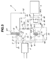
- a double-ended distributorless ignition system "A" having incorporated therein a misfire detecting device includes an ignition coil 1, a battery 2 connected to a primary winding 11 of the ignition coil 1, a power transistor 3, an engine control unit (ECU) 4 for delivering an ignition signal 41 to the power transistor 3, a spark plug 51 connected at a center electrode thereof to a secondary high tension positive terminal 121 of a secondary winding 12, a spark plug 52 connected at a center electrode thereof to a secondary high tension negative terminal 122 of the secondary winding 12, a pulse generating circuit 6 for generating a positive polarity pulse 60, a diode 71 for supplying the positive polarity pulse 60 to the secondary high tension positive terminal 121 of the secondary winding 12, a plug voltage dividing circuit 8 for dividing a plug voltage across the center electrode-to-outer electrode portion of the spark plug 51, and a combustion condition or misfire detecting circuit 9 for detecting a combustion condition within a
- the ignition coil 1 is of the simultaneous ignition or spark type and composed of hundreds of turns of the primary winding 11 and tens of thousands of turns of the secondary winding 12 which are wound on an iron core.
- the iron core is formed from a plurality of thin silicon steel plates which are stacked on upon another.
- the windings are placed in a casing filled with resin.
- the ignition coil 1 has, on the top face of the casing, primary terminals 111 and 112, a secondary high tension positive terminal 121, and a secondary negative terminal 122 which are independent from each other.
- the primary terminal 111 of the ignition coil 1 is connected to a positive terminal 21 of the battery 2, whilst the primary terminal 112 is connected to a collector 31 of the power transistor 3.
- the secondary high tension positive terminal 121 and the secondary high tension negative terminal 122 of the ignition coil 1 are connected by way of high tension codes 511 and 521 to the center electrodes of the spark plugs 51 and 52, respectively.
- the power transistor 3 for allowing battery current to flow intermittently to the primary winding 11 is put into an ON/OFF condition on the basis of an ignition signal 41 delivered from the engine control unit 4 and make the secondary winding 12 develop a high voltage of several tens kilovolts when operated to change from the ON condition to the OFF condition.
- the engine control unit (ECU) 4 determines an optimum ignition timing on the basis of engine speed, coolant temperature, a signal from a cam position sensor, etc. and delivers an ignition signal 41 to the power transistor 3 so that spark discharge is caused at the optimum ignition timing. Further, the engine control unit 4 determines, on the basis of the determined optimum ignition timing, a timing for delivering a high tension pulse 60 and delivers a pulse generation instructing signal 42 to the pulse generating circuit 6.
- primary current supplying means is constituted by the engine control unit 4 and the power transistor 3.
- the spark plugs 51 and 52 are installed on the #1 cylinder and #2 cylinder of a gasoline engine, respectively and adapted to fire or discharge when supplied with, during a compression stroke and an exhaust stroke, a positive high voltage in case of spark plug 51 or a negative high voltage in case of spark plug 52. Since the ignition system is of the double-ended type, the spark plug which is not on the firing cycle is caused to make waste spark or firing during an exhaust stroke. However, since such firing or spark is performed under a nearly atmospheric pressure condition, the required voltage and the arc maintaining voltage are both small so that the firing energy is always and mostly distributed to the spark plug on the firing cycle side.
- the pulse generating circuit 6 in this embodiment is composed of a coil 61 connected at a primary contact 612 of a primary winding 611 to a positive terminal 21 of the battery 2, and a power transistor 62 connected at a collector to an internal connecting terminal 610.
- a high voltage which is not causative of spark discharge or firing (about 3 kV in this embodiment) is produced at a secondary terminal 614 of a secondary winding 613.
- a diode 71 which is connected at an anode 711 to the secondary terminal 614 (i.e., output end of the pulse generating circuit 6) and at an cathode 712 to the secondary high tension positive terminal 121, is a reverse flow preventing, high withstand voltage diode for applying a positive polarity high tension pulse 60 to the secondary positive terminals 121 whilst preventing current of the high voltage for firing of the spark plug 51 from flowing back to the pulse generating circuit 6.
- the plug voltage dividing circuit 8 is constructed of a capacitor 81 of a relative small capacity (e.g., 5 pF) and a capacitor 82 of a relatively large capacity (e.g., 2500 ⁇ 5000 pF) which are connected in series to a high tension code 511 on the spark plug 51 side, and a resistor 83 of a high resistance (e.g., 10 M ⁇ ) connected in parallel to the capacitor 82.
- a capacitor 81 of a relative small capacity e.g., 5 pF
- a capacitor 82 of a relatively large capacity e.g., 2500 ⁇ 5000 pF
- the voltage dividing ratio is 1/1000, the high voltage across the center electrode-to-outer electrode portion of a spark plug is divided and reduced to 1/1000 of the total voltage and the output voltage 800 is input to the misfire detecting circuit 9.
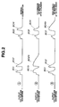
- the misfire detecting circuit 9 detects a misfire of the spark plugs 51 and 52 installed in the respective #1 and #2 cylinders on the basis of the way of attenuation of the output voltage 800 (curves 802 and 804) developed by the application of the positive polarity pulse 60.
- the electrical resistance value between the center electrode and the outer electrode is lowered, so the output voltage 800 attenuates in an early time or shortly.
- the electrical resistance value across the center electrode-to-outer electrode portion of a spark pug is maintained high, so the output voltage 800 attenuates gradually as depicted by the curves 801b and 802b of the waveform 2 in Fig. 2 (occurrence of misfire at #1 cylinder) or by the curve 804b of the waveform 3 in Fig. 2 (occurrence of misfire at #2 cylinder).
- the above described misfire detecting device has the following advantage.
- This embodiment has advantages substantially the same as the above described advantages (b), (e), (i), (j) and (l).
- a positive polarity pulse which is not causative of spark discharge between the center electrode and the outer electrode, is applied to a positive polarity side of a secondary winding by way of a reverse current preventing diode during the time after completion of spark discharge and before beginning of application of high voltage for next spark discharge, and a misfire detecting means detects the combustion condition at each cylinder, i.e., occurrence of a misfire of a spark plug at each cylinder on the basis of an attenuation characteristic of a divided voltage which is a fraction of a plug voltage, across a center electrode-to-outer electrode portion of a spark plug.
- a positive polarity pulse which is not causative of spark discharge between a center electrode and an outer electrode of a spark plug, is applied to a positive polarity side of a secondary winding by way of a first diode and a second diode during the time after completion of spark discharge and before beginning of application of high voltage for next spark discharge, and a misfire detecting means detects the combustion condition at each cylinder, i.e., occurrence of a misfire of a spark plug at each cylinder on the basis of an attenuation characteristic of a divided voltage which is a fraction of a total voltage, at a conjunction between the cathode of the first diode and the anode of the second diode.
- a positive polarity pulse which is not causative of spark discharge between a center electrode and an outer electrode of a spark plug, is applied to a positive polarity side of a secondary winding by way of a first diode and a second diode during the time after completion of spark discharge of a set of spark plugs connected to the same ignition coil during the time after completion of spark discharge of a set of spark plugs connected to the same ignition coil and before beginning of application of high voltage for spark discharge to another set of spark plugs, and a misfire detecting means detects the combustion condition at each cylinder, i.e., occurrence of a misfire of a spark plug at each cylinder on the basis of an attenuation characteristic of a divided voltage which is a fraction of a total voltage, at a conjunction between the cathode of the first diode and the anode of the second diode.
Applications Claiming Priority (12)
| Application Number | Priority Date | Filing Date | Title |
|---|---|---|---|
| JP333898/93 | 1993-12-28 | ||
| JP33389893 | 1993-12-28 | ||
| JP33389893 | 1993-12-28 | ||
| JP3620794 | 1994-03-08 | ||
| JP36207/94 | 1994-03-08 | ||
| JP3620794 | 1994-03-08 | ||
| JP19884894 | 1994-08-24 | ||
| JP19884894 | 1994-08-24 | ||
| JP198848/94 | 1994-08-24 | ||
| JP243944/94 | 1994-10-07 | ||
| JP24394494A JP3277079B2 (ja) | 1993-12-28 | 1994-10-07 | 燃焼状態検出装置 |
| JP24394494 | 1994-10-07 |
Publications (3)
| Publication Number | Publication Date |
|---|---|
| EP0661449A2 true EP0661449A2 (de) | 1995-07-05 |
| EP0661449A3 EP0661449A3 (de) | 1997-09-17 |
| EP0661449B1 EP0661449B1 (de) | 2000-03-08 |
Family
ID=27460227
Family Applications (1)
| Application Number | Title | Priority Date | Filing Date |
|---|---|---|---|
| EP94120838A Expired - Lifetime EP0661449B1 (de) | 1993-12-28 | 1994-12-28 | Vorrichtung zum Erkennen von Fehlzündung bei einer inneren Brennkraftmaschine ausgerüstet mit doppelendiger Spule und verteilerlosem Zündsystem |
Country Status (4)
| Country | Link |
|---|---|
| US (1) | US5503132A (de) |
| EP (1) | EP0661449B1 (de) |
| JP (1) | JP3277079B2 (de) |
| DE (1) | DE69423322T2 (de) |
Cited By (2)
| Publication number | Priority date | Publication date | Assignee | Title |
|---|---|---|---|---|
| EP0801226A2 (de) * | 1996-04-12 | 1997-10-15 | STIEBEL ELTRON GmbH & Co. KG | Verfahren und Vorrichtung zur Auswertung der Qualität eines Kraftstoff-Luftgemisches |
| EP1465342A1 (de) * | 2003-04-01 | 2004-10-06 | STMicroelectronics S.r.l. | Elektronische Mehrkanalzündvorrichtung mit Hochspannungssteuergerät |
Families Citing this family (20)
| Publication number | Priority date | Publication date | Assignee | Title |
|---|---|---|---|---|
| JP3480864B2 (ja) * | 1994-11-09 | 2003-12-22 | 日本特殊陶業株式会社 | 燃焼状態検出方法及び装置 |
| EP0715075B1 (de) * | 1994-12-02 | 1999-08-25 | NGK Spark Plug Co. Ltd. | Vorrichtung zur Erkennung von Fehlzündung einer inneren Brennkraftmaschine |
| JPH08159004A (ja) * | 1994-12-12 | 1996-06-18 | Ngk Spark Plug Co Ltd | 多気筒内燃機関の燃焼状態検出装置 |
| JPH08254555A (ja) * | 1995-01-17 | 1996-10-01 | Ngk Spark Plug Co Ltd | 内燃機関の燃焼状態検出装置 |
| US6104195A (en) * | 1995-05-10 | 2000-08-15 | Denso Corporation | Apparatus for detecting a condition of burning in an internal combustion engine |
| DE19520852C1 (de) * | 1995-06-08 | 1996-09-19 | Vogt Electronic Ag | Vorrichtung und Verfahren zur Zündungserkennung |
| DE19720532C2 (de) * | 1997-05-16 | 1999-04-22 | Telefunken Microelectron | Verfahren zur Bestimmung des Zustandes einer Zündkerze in den Verbrennungsräumen einer Brennkraftmaschine |
| US6425383B1 (en) | 2000-07-06 | 2002-07-30 | Federal-Mogul World Wide, Inc. | Ignition coil with control and driver apparatus having reverse polarity capability |
| US7061245B2 (en) * | 2004-02-06 | 2006-06-13 | Snap-On Incorporated | Coil-on plug capacitive sensors and passive coil-on plug diagnostic system incorporating same |
| US7507701B2 (en) * | 2005-02-25 | 2009-03-24 | Solutions Biomed, Llc | Aqueous disinfectants and sterilants including transition metals |
| CN100458140C (zh) * | 2006-04-07 | 2009-02-04 | 重庆宗申技术开发研究有限公司 | 发动机火花塞异步点火器 |
| JP2009121453A (ja) * | 2007-10-25 | 2009-06-04 | Yamaha Motor Co Ltd | 水ジェット推進艇の失火検出装置 |
| US8286617B2 (en) * | 2010-12-23 | 2012-10-16 | Grady John K | Dual coil ignition |
| US9127638B2 (en) * | 2012-02-08 | 2015-09-08 | Denso Corporation | Control apparatus for internal combustion engine |
| US9022010B2 (en) * | 2012-02-08 | 2015-05-05 | Denso Corporation | Ignition system |
| US9488151B2 (en) * | 2012-02-08 | 2016-11-08 | Denso Corporation | Ignition system |
| JP5907149B2 (ja) * | 2013-11-28 | 2016-04-20 | 株式会社デンソー | 内燃機関の制御装置 |
| CN113464342B (zh) * | 2020-03-31 | 2022-11-29 | 本田技研工业株式会社 | 失火检测装置 |
| US11035334B1 (en) * | 2020-06-12 | 2021-06-15 | Caterpillar Inc. | Engine ignition system and method using sparkplug dry firing to extend service life |
| KR20230037235A (ko) * | 2021-09-09 | 2023-03-16 | 현대자동차주식회사 | 멀티 점화 코일 제어 시스템 |
Citations (6)
| Publication number | Priority date | Publication date | Assignee | Title |
|---|---|---|---|---|
| US4411247A (en) * | 1980-04-24 | 1983-10-25 | Sanke Electric Co., Ltd. | Distributorless ignition system for multicylinder internal-combustion engines |
| JPH04179864A (ja) * | 1990-11-09 | 1992-06-26 | Mitsubishi Electric Corp | イオン電流検出装置 |
| JPH04339175A (ja) * | 1991-05-14 | 1992-11-26 | Ngk Spark Plug Co Ltd | 火花点火機関の失火検出装置 |
| JPH0526145A (ja) * | 1991-05-14 | 1993-02-02 | Ngk Spark Plug Co Ltd | ガソリン機関の失火検出装置 |
| JPH0599113A (ja) * | 1991-08-02 | 1993-04-20 | Ngk Spark Plug Co Ltd | ガソリン機関の失火検出装置 |
| JPH05223050A (ja) * | 1992-02-06 | 1993-08-31 | Honda Motor Co Ltd | 内燃機関の失火検出装置 |
Family Cites Families (4)
| Publication number | Priority date | Publication date | Assignee | Title |
|---|---|---|---|---|
| KR950000221B1 (ko) * | 1990-09-27 | 1995-01-12 | 미쓰비시덴키 가부시키가이샤 | 내연기관용 점화장치 |
| US5293129A (en) * | 1990-11-09 | 1994-03-08 | Mitsubishi Denki Kabushiki Kaisha | Ionic current sensing apparatus for engine spark plug with negative ignition voltage and positive DC voltage application |
| US5283527A (en) * | 1991-06-28 | 1994-02-01 | Ford Motor Company | Methods and apparatus for detecting short circuited secondary coil winding via monitoring primary coil winding |
| DE69331790T2 (de) * | 1992-09-11 | 2002-08-08 | Ngk Spark Plug Co | Fehlzündungsdetektor mit verschiedenen Methoden bei hoher und niedriger Motorgeschwindigkeit |
-
1994
- 1994-10-07 JP JP24394494A patent/JP3277079B2/ja not_active Expired - Fee Related
- 1994-12-28 US US08/364,998 patent/US5503132A/en not_active Expired - Lifetime
- 1994-12-28 EP EP94120838A patent/EP0661449B1/de not_active Expired - Lifetime
- 1994-12-28 DE DE69423322T patent/DE69423322T2/de not_active Expired - Fee Related
Patent Citations (6)
| Publication number | Priority date | Publication date | Assignee | Title |
|---|---|---|---|---|
| US4411247A (en) * | 1980-04-24 | 1983-10-25 | Sanke Electric Co., Ltd. | Distributorless ignition system for multicylinder internal-combustion engines |
| JPH04179864A (ja) * | 1990-11-09 | 1992-06-26 | Mitsubishi Electric Corp | イオン電流検出装置 |
| JPH04339175A (ja) * | 1991-05-14 | 1992-11-26 | Ngk Spark Plug Co Ltd | 火花点火機関の失火検出装置 |
| JPH0526145A (ja) * | 1991-05-14 | 1993-02-02 | Ngk Spark Plug Co Ltd | ガソリン機関の失火検出装置 |
| JPH0599113A (ja) * | 1991-08-02 | 1993-04-20 | Ngk Spark Plug Co Ltd | ガソリン機関の失火検出装置 |
| JPH05223050A (ja) * | 1992-02-06 | 1993-08-31 | Honda Motor Co Ltd | 内燃機関の失火検出装置 |
Non-Patent Citations (5)
| Title |
|---|
| PATENT ABSTRACTS OF JAPAN vol. 016, no. 494 (M-1324), 13 October 1992 & JP 04 179864 A (MITSUBISHI ELECTRIC CORP), 26 June 1992, & DE 41 36 835 A (MITSUBISHI DENKI K.K.) 14 May 1992 * |
| PATENT ABSTRACTS OF JAPAN vol. 017, no. 191 (M-1396) 14 April 1993 & JP 04 339 175 A (NGK SPARK PLUG CO LTD) 26 November 1992 * |
| PATENT ABSTRACTS OF JAPAN vol. 017, no. 306 (M-1428) 11 June 1993 & JP 05 026 145 A (NGK SPARK PLUG CO LTD) 02 February 1993 * |
| PATENT ABSTRACTS OF JAPAN vol. 017, no. 447 (M-1464) 17 August 1993 & JP 05 099 113 A (NGK SPARK PLUG CO LTD) 20 April 1993 * |
| PATENT ABSTRACTS OF JAPAN vol. 017, no. 671 (M-1525) 10 December 1993 & JP 05 223 050 A (HONDA MOTOR CO LTD) 31 August 1993 * |
Cited By (4)
| Publication number | Priority date | Publication date | Assignee | Title |
|---|---|---|---|---|
| EP0801226A2 (de) * | 1996-04-12 | 1997-10-15 | STIEBEL ELTRON GmbH & Co. KG | Verfahren und Vorrichtung zur Auswertung der Qualität eines Kraftstoff-Luftgemisches |
| EP0801226A3 (de) * | 1996-04-12 | 1999-05-06 | STIEBEL ELTRON GmbH & Co. KG | Verfahren und Vorrichtung zur Auswertung der Qualität eines Kraftstoff-Luftgemisches |
| EP1465342A1 (de) * | 2003-04-01 | 2004-10-06 | STMicroelectronics S.r.l. | Elektronische Mehrkanalzündvorrichtung mit Hochspannungssteuergerät |
| US7021299B2 (en) | 2003-04-01 | 2006-04-04 | Stmicroelectronics S.R.L. | Multichannel electronic ignition device with high-voltage controller |
Also Published As
| Publication number | Publication date |
|---|---|
| US5503132A (en) | 1996-04-02 |
| DE69423322T2 (de) | 2000-07-27 |
| DE69423322D1 (de) | 2000-04-13 |
| EP0661449B1 (de) | 2000-03-08 |
| JPH08114170A (ja) | 1996-05-07 |
| JP3277079B2 (ja) | 2002-04-22 |
| EP0661449A3 (de) | 1997-09-17 |
Similar Documents
| Publication | Publication Date | Title |
|---|---|---|
| EP0661449B1 (de) | Vorrichtung zum Erkennen von Fehlzündung bei einer inneren Brennkraftmaschine ausgerüstet mit doppelendiger Spule und verteilerlosem Zündsystem | |
| US4463744A (en) | Distributorless ignition system with surge absorbing means and apparatus therefor | |
| US4366801A (en) | Plasma ignition system | |
| US6054859A (en) | Combustion state detecting apparatus for internal combustion engine | |
| US6799451B2 (en) | Spark generating apparatus having strain gage cylinder pressure measurement feature | |
| GB2085076A (en) | Plasma ignition system | |
| US6679236B2 (en) | Ignition system having a high resistivity core | |
| JP3593457B2 (ja) | 内燃機関の点火二次回路用センサ、点火・燃焼検出装置、及びプレイグニッション検出装置 | |
| EP0658692B1 (de) | Verfahren und Vorrichtung zum Erkennen von Fehlerzündung eines Motorzündsystemes | |
| EP0723078B1 (de) | Vorrichtung zur Fehlzündungserkennung in einer inneren Brennkraftmaschine | |
| JP3188757B2 (ja) | 点火コイル構造 | |
| US6216530B1 (en) | Combustion state detecting device for an internal combustion engine | |
| US6359439B1 (en) | Compression sense ignition system with fault mode detection and having improved capacitive sensing | |
| EP0715075A2 (de) | Vorrichtung zur Erkennung von Fehlzündung einer inneren Brennkraftmaschine | |
| US5327867A (en) | Misfire-detecting system for internal combustion engines | |
| EP0711917B1 (de) | Zündaussetzererkennungsvorrichtung und Verfahren für eine innere Benzinbrennkraftmaschine | |
| EP0665376B1 (de) | Zündaussetzererkennungsvorrichtung | |
| US6700470B2 (en) | Ignition apparatus having increased leakage to charge ion sense system | |
| EP0663526B1 (de) | Zündsystem einer inneren Brennkraftmaschine | |
| US6679235B1 (en) | High power ignition system having high impedance to protect the transformer | |
| US5727534A (en) | Misfire detecting device for multi-cylinder internal combustion engine | |
| JPH0874718A (ja) | 燃焼状態検出装置 | |
| JP2666108B2 (ja) | 点火コイル装置 |
Legal Events
| Date | Code | Title | Description |
|---|---|---|---|
| PUAI | Public reference made under article 153(3) epc to a published international application that has entered the european phase |
Free format text: ORIGINAL CODE: 0009012 |
|
| AK | Designated contracting states |
Kind code of ref document: A2 Designated state(s): DE GB |
|
| PUAL | Search report despatched |
Free format text: ORIGINAL CODE: 0009013 |
|
| AK | Designated contracting states |
Kind code of ref document: A3 Designated state(s): DE GB |
|
| 17P | Request for examination filed |
Effective date: 19980128 |
|
| 17Q | First examination report despatched |
Effective date: 19980911 |
|
| GRAG | Despatch of communication of intention to grant |
Free format text: ORIGINAL CODE: EPIDOS AGRA |
|
| GRAG | Despatch of communication of intention to grant |
Free format text: ORIGINAL CODE: EPIDOS AGRA |
|
| GRAG | Despatch of communication of intention to grant |
Free format text: ORIGINAL CODE: EPIDOS AGRA |
|
| GRAH | Despatch of communication of intention to grant a patent |
Free format text: ORIGINAL CODE: EPIDOS IGRA |
|
| GRAH | Despatch of communication of intention to grant a patent |
Free format text: ORIGINAL CODE: EPIDOS IGRA |
|
| GRAA | (expected) grant |
Free format text: ORIGINAL CODE: 0009210 |
|
| AK | Designated contracting states |
Kind code of ref document: B1 Designated state(s): DE GB |
|
| REF | Corresponds to: |
Ref document number: 69423322 Country of ref document: DE Date of ref document: 20000413 |
|
| EN | Fr: translation not filed | ||
| PLBE | No opposition filed within time limit |
Free format text: ORIGINAL CODE: 0009261 |
|
| STAA | Information on the status of an ep patent application or granted ep patent |
Free format text: STATUS: NO OPPOSITION FILED WITHIN TIME LIMIT |
|
| 26N | No opposition filed | ||
| REG | Reference to a national code |
Ref country code: GB Ref legal event code: IF02 |
|
| PGFP | Annual fee paid to national office [announced via postgrant information from national office to epo] |
Ref country code: GB Payment date: 20031224 Year of fee payment: 10 |
|
| PGFP | Annual fee paid to national office [announced via postgrant information from national office to epo] |
Ref country code: DE Payment date: 20040108 Year of fee payment: 10 |
|
| PG25 | Lapsed in a contracting state [announced via postgrant information from national office to epo] |
Ref country code: GB Free format text: LAPSE BECAUSE OF NON-PAYMENT OF DUE FEES Effective date: 20041228 |
|
| PG25 | Lapsed in a contracting state [announced via postgrant information from national office to epo] |
Ref country code: DE Free format text: LAPSE BECAUSE OF NON-PAYMENT OF DUE FEES Effective date: 20050701 |
|
| GBPC | Gb: european patent ceased through non-payment of renewal fee |
Effective date: 20041228 |