EP0661173A1 - Chip card with integrated module - Google Patents
Chip card with integrated module Download PDFInfo
- Publication number
- EP0661173A1 EP0661173A1 EP94112977A EP94112977A EP0661173A1 EP 0661173 A1 EP0661173 A1 EP 0661173A1 EP 94112977 A EP94112977 A EP 94112977A EP 94112977 A EP94112977 A EP 94112977A EP 0661173 A1 EP0661173 A1 EP 0661173A1
- Authority
- EP
- European Patent Office
- Prior art keywords
- recess
- layer
- transparent
- card
- transparent cover
- Prior art date
- Legal status (The legal status is an assumption and is not a legal conclusion. Google has not performed a legal analysis and makes no representation as to the accuracy of the status listed.)
- Withdrawn
Links
Images

Classifications
-
- B—PERFORMING OPERATIONS; TRANSPORTING
- B32—LAYERED PRODUCTS
- B32B—LAYERED PRODUCTS, i.e. PRODUCTS BUILT-UP OF STRATA OF FLAT OR NON-FLAT, e.g. CELLULAR OR HONEYCOMB, FORM
- B32B38/00—Ancillary operations in connection with laminating processes
-
- G—PHYSICS
- G06—COMPUTING; CALCULATING OR COUNTING
- G06K—GRAPHICAL DATA READING; PRESENTATION OF DATA; RECORD CARRIERS; HANDLING RECORD CARRIERS
- G06K19/00—Record carriers for use with machines and with at least a part designed to carry digital markings
- G06K19/06—Record carriers for use with machines and with at least a part designed to carry digital markings characterised by the kind of the digital marking, e.g. shape, nature, code
- G06K19/067—Record carriers with conductive marks, printed circuits or semiconductor circuit elements, e.g. credit or identity cards also with resonating or responding marks without active components
- G06K19/07—Record carriers with conductive marks, printed circuits or semiconductor circuit elements, e.g. credit or identity cards also with resonating or responding marks without active components with integrated circuit chips
- G06K19/077—Constructional details, e.g. mounting of circuits in the carrier
- G06K19/07745—Mounting details of integrated circuit chips
-
- B—PERFORMING OPERATIONS; TRANSPORTING
- B32—LAYERED PRODUCTS
- B32B—LAYERED PRODUCTS, i.e. PRODUCTS BUILT-UP OF STRATA OF FLAT OR NON-FLAT, e.g. CELLULAR OR HONEYCOMB, FORM
- B32B2425/00—Cards, e.g. identity cards, credit cards
-
- H—ELECTRICITY
- H01—ELECTRIC ELEMENTS
- H01L—SEMICONDUCTOR DEVICES NOT COVERED BY CLASS H10
- H01L2924/00—Indexing scheme for arrangements or methods for connecting or disconnecting semiconductor or solid-state bodies as covered by H01L24/00
- H01L2924/0001—Technical content checked by a classifier
- H01L2924/0002—Not covered by any one of groups H01L24/00, H01L24/00 and H01L2224/00
Definitions
- the invention relates to identity cards with an opaque core layer, with at least one transparent cover layer and with a recess for receiving an electronic module with an integrated circuit, the recess projecting up to or into the transparent rear layer.
- the invention further relates to a method for producing such identity cards.
- Identification cards with an electronic module that contains an integrated circuit have been known for a long time and are provided for a wide variety of applications.
- the external dimensions of such ID cards are the same for all uses of the card and are specified in a standard.
- a large part of the identity cards is now manufactured using so-called assembly technology, i.e. H. a finished card body is provided with a recess into which the electronic module is inserted.
- the depth of the recess is determined by the thickness of the module to be used and the requirement that the maximum thickness of the card in the module area specified in the standard must not be exceeded. Since, depending on the design, the module has a thickness that is generally significantly greater than half the maximum thickness of the card, the bottom of the recess in the card body is relatively thin.
- ID cards which are largely made up of an opaque core layer and very thin front and back transparent cover layers, the bottom of the recess is still in the opaque core layer, so that the recess and the module located in it cannot be seen through the bottom of the recess are.
- ID cards with thicker front and back transparent cover layers, the core layer of which is correspondingly thinner.
- Such card structures are used, for example, when security-relevant data are written into the volume of one of the transparent cover layers of the card with the aid of a laser.
- This form of labeling ID cards is particularly forgery-proof, since the data written into the volume of a thicker layer is not so easy, e.g. B. by "scraping", can be removed and changed without visibly damaging the card.
- the thickness of the transparent layer into which the data is written is therefore predetermined within a certain range.
- both cover layers are generally chosen to have the same thickness, so that a thickness of between approximately 30% and 70% of the card thickness is available for the opaque, generally white-colored core layer.
- the so-called assembly technology is often used to install the electronic module in the card body, i. H. it is first provided a finished card body, in which the recess for receiving the electronic module, for. B. is created by milling.
- the cutout for receiving the electronic module protrudes up to or into the transparent cover layer on the rear side, so that the contour of the cutout and the module located in it are due to the now transparent bottom of the cutout see is.
- the visual appearance of such cards is consequently impaired.
- the visible part of the recess is also annoying because the back of the card also holds a Magnetic stripe and a signature strip and used for printing technology.
- the basic idea of the invention is to take measures within the card body by means of which the area of the card body which contains the part of the recess which projects into the back cover layer is optically upgraded. This goal can be achieved by taking the measures either directly in the recess or in the layer structure of the card body.
- a first possibility consists in optically adapting the part of the cutout which extends up to or into the transparent back layer into the opaque core layer of the card body, so that the cutout and the module located therein can hardly be seen.
- the optical adjustment of the recess can be achieved either by measures that are taken on the recess in the card body before the module is inserted into the card body, or by measures that are taken on the electronic module itself.
- Another possibility of optically upgrading the part of the cutout that extends up to or into the transparent rear layer is to provide this part of the cutout with an optically appealing element that differs from the opaque core layer of the Card takes off. It is particularly advantageous if an element that is difficult to manufacture is inserted into the recess. Such an element can be used as an additional authenticity feature, which allows the card user to visually check the authenticity of the card.
- the rear transparent part of the card body can be formed by two layers such that the part of the recess which projects into the rear transparent part lies in the transparent layer which is located between the core layer and the rear cover layer.
- an element can be provided between the two transparent layers, which covers the above-mentioned area of the recess, so that when the card is viewed from the rear, it is hardly or no longer visible.
- the contour of the cutout is printed with a material whose color is matched as well as possible to the opaque core layer of the identification card.
- a liquid thermal adhesive can be selected as the material for printing the contour of the recess, with the aid of which the electronic module is later glued into the card body. In this case, it is particularly advantageous if the entire contour of the recess is printed in order to achieve the greatest possible adhesive effect. Alternatively, however, only that contour of the cutout that projects into or protrudes into the rear, transparent cover layer can be printed with a color that largely corresponds to the color of the opaque core layer.
- the cutout can be filled with a casting resin which is matched to the color of the opaque core layer.
- a casting resin which is matched to the color of the opaque core layer.
- a color-matched liquid adhesive or heat seal adhesive can also be inserted into the recess, via which the electronic module, which may be provided with a casting resin, is connected to the card body.
- the part of the recess provided in it can be introduced into the rear transparent cover layer before the individual card layers are laminated.
- the card layers soften somewhat, so that material flows from the core layer into the recess in the back cover layer. Now bring it into the card body, e.g. B. by milling, the recess for the module, the part of the recess, which is located in the rear transparent cover layer, is provided with a thin opaque layer.
- a layer is introduced into the cutout of the card body, which on the side that can be seen when the finished identification card is viewed from the rear, with information, for. B.
- information for. B.
- This information can either be printed on the layer or stamped into it.
- a hologram is introduced into the cutout of the card body, which can be seen when the finished identification cards are viewed from the rear.
- Both the layer and the hologram not only visually enhance the ID card, but also serve as an authenticity feature of the card.
- Holograms in particular are difficult to produce and can only be copied by a counterfeiter with great effort, which often exceeds the benefits.
- the hologram in the recess is very well protected, since it is integrated into the layered composite in the finished ID card and can therefore only be removed from a real card if one either destroys the bottom of the recess or the electronic module from the recess away. In both cases, the hologram is likely to be damaged.
- the counterfeiter has hardly any way of getting a real undamaged hologram and totally falsifying a card.
- the transparent back layer overlying the hologram offers good protection against damage to the hologram.
- Fig. 1 shows an identity card with electronic module 4 in plan view.
- the front cover layer 6 is transparent.
- alphanumeric data 8 are written, such as. B.
- the data 8 z. B. be written into the transparent cover layer by means of a laser in such a way that the penetrate the entire volume of the layer.
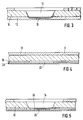
- Fig. 2 shows a multi-layer card body with a recess in cross section.
- the card body is constructed from the front transparent cover layer 6, the opaque core layer 10 and the rear transparent cover layer 12.
- the alphanumeric data 8 are written into the volume of the cover layer 6.
- the cover layer 6 has a sufficiently large thickness which makes the removal of this layer in the area of the alphanumeric data 8 and, if appropriate, the addition of new data apparent, and thus makes it difficult to forge the data.
- the cover layer 6 is formed with a thickness of approximately 100 ⁇ m upwards, layers which are preferably used have a thickness of approximately 200 ⁇ m.
- the rear transparent cover layer 12 is of the same thickness for reasons of symmetry.
- the thickness of the opaque layer 10 is determined from the total thickness of the card of approximately 800 ⁇ m specified in a standard and is therefore approximately 400 ⁇ m for cover layers 8 or 10 having a thickness of 200 ⁇ m.
- a recess 14 is made for receiving an electronic module, the overall height of which, depending on the type, is approximately 500 to 700 ⁇ m.
- the depth of the recess is chosen so that any tolerances in the overall height of the module can be absorbed, so it is approximately 600 to 725 ⁇ m.
- the cutout 14 thus projects up to the rear transparent cover layer 12 or partially into it, as can be seen in FIG. 2.
- the finished card therefore, if you look at the back of the card, you can see the electronic module in the recess and its contour, which affects the visual appearance of the ID card.
- Fig. 3 shows the card body with recess from Fig. 2 in cross section as far as possible.
- that part of the cutout which lies in the rear transparent cover layer is provided with a layer 16 which is matched to the optical appearance of the opaque core layer 10.
- the layer can be introduced into the cutout 14 in various ways. It is Z. B. possible to generate the layer in pad printing or in the transfer printing process. Appropriate techniques are known to the person skilled in the art and need not be explained in more detail here. Since the layer 16 is optically matched to the opaque core layer 10, the electronic module can no longer be seen from the back of the card and the contour of the recess 14 can only be seen with difficulty in the finished identification card.
- the layer 16 can be designed as a thermally activatable adhesive, by means of which the electronic module is connected to the card body.
- the structure of the card body differs from the structures shown so far in that the rear transparent cover layer 12 consists of two transparent layers 18 and 20.
- the transparent layer 18 is provided with a window 22, which in its size and shape roughly corresponds to that part of the cutout 14 in FIG. 2 which lies in the rear transparent cover layer 12.
- the layers 6, 10, 18 and 20 are then placed on top of one another and laminated, as shown in FIG. 4, that is to say bonded to one another under the action of heat and pressure.
- the layers soften and the window 22 in the layer 18 becomes coexistent with the lamination Material filled out of the opaque core layer 10.
- a depression corresponding to the window 22 in the layer 18 forms in the surface of the layer 6, but this is of no importance since this area of the card body is removed when the recess 14 is formed.
- FIG. 5 shows the card body from FIG. 4 with the recess 14, which can be produced, for example, by milling.
- the area 26 below the bottom area 24 of the cutout 14 lies in the transparent back of the card, but nevertheless consists of the material of the opaque core layer 10, since the window shown in FIG. 4 was filled with this material during lamination and during Creating the recess 14 is milled into this material.
- the area 26 below the bottom area 24 can be made very thin, since accuracies of a few ⁇ m can be achieved during milling. If an electronic module is inserted into the cutout of the card body shown in FIG. 5, the contour of the cutout 14 cannot be seen from the back of the card, nor can the module itself be seen in the cutout.
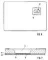
- Fig. 6 shows the back of an identification card in plan view.
- the cross section of the card body largely corresponds to that shown in FIG. 3.
- the layer 16, which covers at least the part of the cutout which projects towards or projects into the transparent rear cover layer 12, is designed as a metallic layer in the example shown in FIG. 6 and clearly stands out from the opaque core layer of the card that you can see when looking back at the card through the transparent back layer.
- the layer 16 can also be designed in any other way in order to achieve this effect.
- the metallic Layer 16 contains information, e.g. B. in the form of a company logo 28, which is either printed on the metallic layer 16 or embossed into this layer.
- the metallic layer is integrated in the card structure and is protected by the transparent rear layer 12 in the finished card. It is also possible to emboss a holographic structure into the metallic layer and to insert the hologram thus created into the recess in the card body.
- FIG. 7 again shows a card body with a recess in cross section, the rear transparent cover layer of which is composed of two transparent layers 18 and 20.
- the thickness of the layer 18 is selected such that the bottom region 24 of the recess 14 lies in this layer.
- an additional layer 30 is already introduced in some areas during the production of the card body in such a way that the part of the recess 14 lying in the layer 18 is completely covered in the finished identification card. In this case, the electronic module in the cutout and the contour of the cutout can no longer be seen from the back of the finished card.
- the additional layer 30 can either be designed as a print layer, color layer or hologram etc.
- ID cards that are used for certain applications e.g. B. banking applications are provided, often have a signature strip or similar elements in the surface of the rear transparent cover layer, which already partially cover the part of the recess to be seen from the back of the card. In this case it is possible to cover with the additional layer 30 only the remaining area of the part of the recess 14 lying in the layer 18, which would otherwise remain free and would therefore be visible.
Landscapes
- Engineering & Computer Science (AREA)
- Computer Hardware Design (AREA)
- Microelectronics & Electronic Packaging (AREA)
- Physics & Mathematics (AREA)
- General Physics & Mathematics (AREA)
- Theoretical Computer Science (AREA)
- Credit Cards Or The Like (AREA)
Abstract
Die Erfindung betrifft Ausweiskarten mit einer opaken Kernschicht (10) und mindestens einer transparenten Deckschicht (6) und mit einer Aussparung (14) zur Aufnahme eines elektronischen Moduls (4). Ein Teil der Aussparung reicht bis an die transparente Deckschicht (6) heran bzw. in diese hinein. Dieser Teil der Aussparung wird optisch aufgewertet, um das Erscheinungsbild der Karte zu verbessern. Dies kann beispielsweise durch Bedrucken der Aussparung (14) oder durch Einbringung eines zusätzlichen Elements in die Aussparung (14) geschehen, das auch als Echtheitsmerkmal für die Karte dienen kann.The invention relates to identity cards with an opaque core layer (10) and at least one transparent cover layer (6) and with a recess (14) for receiving an electronic module (4). A part of the recess extends up to or into the transparent cover layer (6). This part of the recess is visually upgraded to improve the appearance of the card. This can be done, for example, by printing the recess (14) or by introducing an additional element into the recess (14), which can also serve as an authenticity feature for the card.
Description
Die Erfindung betrifft Ausweiskarten mit einer opaken Kernschicht, mit wenigstens einer transparenten Deckschicht und mit einer Aussparung zur Aufnahme eines elektronischen Moduls mit einem integrierten Schaltkreis, wobei die Aussparung bis an die transparente rückseitige Schicht heran- oder in diese hineinragt. Ferner betrifft die Erfindung ein Verfahren zur Herstellung solcher Ausweiskarten.The invention relates to identity cards with an opaque core layer, with at least one transparent cover layer and with a recess for receiving an electronic module with an integrated circuit, the recess projecting up to or into the transparent rear layer. The invention further relates to a method for producing such identity cards.
Ausweiskarten mit einem elektronischen Modul, das einen integrierten Schaltkreis enthält, sind seit langer Zeit bekannt und werden für die verschiedensten Anwendungen bereitgestellt. Die äußeren Abmaße solcher Ausweiskarten sind für alle Anwendungen der Karte gleich und in einer Norm festgelegt. Ein großer Teil der Ausweiskarten wird heute in sogenannter Montagetechnik gefertigt, d. h. es wird ein fertiger Kartenkörper mit einer Aussparung bereitgestellt, in die das elektronische Modul eingesetzt wird. Die Tiefe der Aussparung bestimmt sich aus der Dicke des einzusetzenden Moduls und der Forderung, daß die in der Norm festgelegte Maximaldicke der Karte im Modulbereich nicht überschritten werden darf. Da je nach Bauart das Modul eine Dicke aufweist, die im allgemeinen deutlich größer als die Hälfte der Maximaldicke der Karte ist, ist der Boden der Aussparung im Kartenkörper relativ dünn.Identification cards with an electronic module that contains an integrated circuit have been known for a long time and are provided for a wide variety of applications. The external dimensions of such ID cards are the same for all uses of the card and are specified in a standard. A large part of the identity cards is now manufactured using so-called assembly technology, i.e. H. a finished card body is provided with a recess into which the electronic module is inserted. The depth of the recess is determined by the thickness of the module to be used and the requirement that the maximum thickness of the card in the module area specified in the standard must not be exceeded. Since, depending on the design, the module has a thickness that is generally significantly greater than half the maximum thickness of the card, the bottom of the recess in the card body is relatively thin.
Bei Ausweiskarten, die weitestgehend aus einer opaken Kernschicht und sehr dünnen vorder- und rückseitigen transparenten Deckschichten aufgebaut sind, liegt der Boden der Aussparung dennoch in der opaken Kernschicht, so daß die Aussparung und das in ihr befindliche Modul durch den Boden der Aussparung nicht zu sehen sind.With ID cards, which are largely made up of an opaque core layer and very thin front and back transparent cover layers, the bottom of the recess is still in the opaque core layer, so that the recess and the module located in it cannot be seen through the bottom of the recess are.
Es gibt jedoch Ausweiskarten mit dickeren vorder- und rückseitigen transparenten Deckschichten, deren Kernschicht entsprechend dünner ausgebildet ist. Solche Kartenaufbauten werden beispielsweise dann verwendet, wenn sicherheitsrelevante Daten mit Hilfe eines Lasers in das Volumen einer der transparenten Deckschichten der Karte eingeschrieben werden. Diese Form der Beschriftung von Ausweiskarten ist besonders fälschungssicher, da die in das Volumen einer dickeren Schicht eingeschriebenen Daten nicht so einfach, z. B. durch "Abkratzen", entfernt und verändert werden können, ohne die Karte augenfällig zu beschädigen. Die Dicke der transparenten Schicht, in die die Daten eingeschrieben werden, ist also in einem gewissen Rahmen vorgegeben. Ferner werden im allgemeinen aus Symmetriegründen beide Deckschichten gleich dick gewählt, so daß für die opake, im allgemeinen weiß eingefärbte Kernschicht eine Dicke zwischen etwa 30 % und 70 % der Kartendicke zur Verfügung steht.However, there are ID cards with thicker front and back transparent cover layers, the core layer of which is correspondingly thinner. Such card structures are used, for example, when security-relevant data are written into the volume of one of the transparent cover layers of the card with the aid of a laser. This form of labeling ID cards is particularly forgery-proof, since the data written into the volume of a thicker layer is not so easy, e.g. B. by "scraping", can be removed and changed without visibly damaging the card. The thickness of the transparent layer into which the data is written is therefore predetermined within a certain range. Furthermore, for reasons of symmetry, both cover layers are generally chosen to have the same thickness, so that a thickness of between approximately 30% and 70% of the card thickness is available for the opaque, generally white-colored core layer.
Bei Ausweiskarten des obengenannten Typs wird zum Einbau des elektronischen Moduls in den Kartenkörper häufig die sogenannte Montagetechnik verwendet, d. h. es wird zunächst ein fertiggestellter Kartenkörper bereitgestellt, in dem nachträglich die Aussparung zur Aufnahme des elektronischen Moduls, z. B. durch Fräsen, erstellt wird.In ID cards of the type mentioned above, the so-called assembly technology is often used to install the electronic module in the card body, i. H. it is first provided a finished card body, in which the recess for receiving the electronic module, for. B. is created by milling.
Bei derartig hergestellten Karten mit dickeren transparenten Deckschichten ragt die Aussparung für die Aufnahme des elektronischen Moduls bis an die rückseitige transparente Deckschicht heran bzw. in diese hinein, so daß durch den nunmehr transparenten Boden der Aussparung die Kontur der Aussparung und das in ihr befindliche Modul zu sehen ist. Das optische Erscheinungsbild solcher Karten ist folglich beeinträchtigt. Darüber hinaus stört der sichtbare Teil der Aussparung auch deswegen, weil die Rückseite der Karte auch zur Unterbringung eines Magnetstreifens und eines Unterschriftsstreifens und zur drucktechnischen Gestaltung genutzt wird.In the case of cards produced in this way with thicker transparent cover layers, the cutout for receiving the electronic module protrudes up to or into the transparent cover layer on the rear side, so that the contour of the cutout and the module located in it are due to the now transparent bottom of the cutout see is. The visual appearance of such cards is consequently impaired. In addition, the visible part of the recess is also annoying because the back of the card also holds a Magnetic stripe and a signature strip and used for printing technology.
Es ist deshalb Aufgabe der Erfindung, bei Ausweiskarten des obigen Typs das optische Erscheinungsbild der Karte zu verbessern.It is therefore an object of the invention to improve the visual appearance of the card in identity cards of the above type.
Die Aufgabe wird durch die Merkmale der nebenangeordneten Ansprüche 1, 8 und 13 gelöst.The object is achieved by the features of the
Der Grundgedanke der Erfindung besteht darin, innerhalb des Kartenkörpers Maßnahmen zu ergreifen, durch die der Bereich des Kartenkörpers, der den in die rückseitige Deckschicht ragenden Teil der Aussparung enthält, optisch aufgewertet wird. Dieses Ziel kann dadurch erreicht werden, daß man die Maßnahmen entweder direkt in der Aussparung oder im Schichtaufbau des Kartenkörpers vornimmt. Eine erste Möglichkeit besteht darin, den Teil der Aussparung, der bis an die transparente rückseitige Schicht heran- bzw. in diese hineinragt optisch an die opake Kernschicht des Kartenkörpers anzupassen, so daß die Aussparung und das in ihr befindliche Modul kaum noch zu sehen sind. Die optische Anpassung der Aussparung kann entweder durch Maßnahmen, die man an der Aussparung im Kartenkörper vor dem Einsetzen des Moduls in den Kartenkörper oder aber durch Maßnahmen, die man an dem elektronischen Modul selbst vornimmt, erreicht werden.The basic idea of the invention is to take measures within the card body by means of which the area of the card body which contains the part of the recess which projects into the back cover layer is optically upgraded. This goal can be achieved by taking the measures either directly in the recess or in the layer structure of the card body. A first possibility consists in optically adapting the part of the cutout which extends up to or into the transparent back layer into the opaque core layer of the card body, so that the cutout and the module located therein can hardly be seen. The optical adjustment of the recess can be achieved either by measures that are taken on the recess in the card body before the module is inserted into the card body, or by measures that are taken on the electronic module itself.
Eine andere Möglichkeit, den Teil der Aussparung, der bis an die transparente rückseitige Schicht heran- bzw. in diese hereinragt, optisch aufzuwerten, besteht darin, daß man diesen Teil der Aussparung mit einem optisch ansprechenden Element versieht, das sich von der opaken Kernschicht der Karte abhebt. Dabei ist es besonders vorteilhaft, wenn man ein schwierig herzustellendes Element in die Aussparung einsetzt. Ein solches Element kann als zusätzliches Echtheitsmerkmal verwendet werden, das es dem Kartenbenutzer erlaubt, die Echtheit der Karte visuell zu überprüfen.Another possibility of optically upgrading the part of the cutout that extends up to or into the transparent rear layer is to provide this part of the cutout with an optically appealing element that differs from the opaque core layer of the Card takes off. It is particularly advantageous if an element that is difficult to manufacture is inserted into the recess. Such an element can be used as an additional authenticity feature, which allows the card user to visually check the authenticity of the card.
Schließlich kann der rückseitige transparente Teil des Kartenkörpers durch zwei Schichten derart gebildet werden, daß derjenige Teil der Aussparung, der in den rückseitigen transparenten Teil ragt, in der transparenten Schicht liegt, die sich zwischen der Kernschicht und der rückseitigen Deckschicht befindet. In diesem Fall kann zwischen den beiden transparenten Schichten ein Element vorgesehen werden, das den obengenannten Bereich der Aussparung abdeckt, so daß dieser bei rückwärtiger Betrachtung der Karte kaum bzw. nicht mehr sichtbar ist.Finally, the rear transparent part of the card body can be formed by two layers such that the part of the recess which projects into the rear transparent part lies in the transparent layer which is located between the core layer and the rear cover layer. In this case, an element can be provided between the two transparent layers, which covers the above-mentioned area of the recess, so that when the card is viewed from the rear, it is hardly or no longer visible.
Gemäß einem ersten Ausführungsbeispiel der Erfindung wird die Kontur der Aussparung mit einem Material bedruckt, das in seiner Farbgebung möglichst gut an die opake Kernschicht der Ausweiskarte angepaßt ist.According to a first exemplary embodiment of the invention, the contour of the cutout is printed with a material whose color is matched as well as possible to the opaque core layer of the identification card.
Dies kann beispielsweise im Tampondruckverfahren oder im Transferdruckverfahren geschehen. Als Material zum Bedrucken der Kontur der Aussparung kann ein flüssiger Thermokleber gewählt werden, mit dessen Hilfe das elektronische Modul später im Kartenkörper verklebt wird. In diesem Fall ist es besonders vorteilhaft, wenn die gesamte Kontur der Aussparung bedruckt wird, um eine möglichst große Klebewirkung zu erzielen. Alternativ kann aber auch nur diejenige Kontur der Aussparung, die in die rückseitige, transparente Deckschicht heranragt bzw. in diese hineinragt, mit einer Farbe bedruckt werden, die weitestgehend mit der Farbe der opaken Kernschicht übereinstimmt.This can be done, for example, in the pad printing process or in the transfer printing process. A liquid thermal adhesive can be selected as the material for printing the contour of the recess, with the aid of which the electronic module is later glued into the card body. In this case, it is particularly advantageous if the entire contour of the recess is printed in order to achieve the greatest possible adhesive effect. Alternatively, however, only that contour of the cutout that projects into or protrudes into the rear, transparent cover layer can be printed with a color that largely corresponds to the color of the opaque core layer.
Gemäß einem weiteren Ausführungsbeispiel der Erfindung kann die Aussparung mit einem in der Farbe der opaken Kernschicht angepaßten Gießharz angefüllt werden. Danach wird ein elektronisches Modul mit einem integrierten Schaltkreis und Leiterbahnen, die den integrierten Schaltkreis mit auf dem Modul liegenden Kontaktflächen verbinden, in die Aussparung eingesetzt. Das Gießharz ist so zu dosieren, daß hierbei der Schaltkreis und die Leiterbahnen zum Schutz vor mechanischen Belastungen von ihm umgeben werden und bei der fertiggestellten Ausweiskarte zumindest der in der rückseitigen transparenten Deckschicht liegende Teil der Aussparung vollständig mit Gießharz gefüllt ist. Um die Dosierung des Gießharzes zu erleichtern, können in der opaken Kernschicht Ausgleichshohlräume geschaffen werden, die mit der Aussparung in Verbindung stehen und in die gegebenenfalls überschüssiges Gießharz abfließen kann.According to a further exemplary embodiment of the invention, the cutout can be filled with a casting resin which is matched to the color of the opaque core layer. After that an electronic module with an integrated circuit and conductor tracks which connect the integrated circuit with contact surfaces lying on the module are inserted into the recess. The casting resin is to be dosed so that the circuit and the conductor tracks for protection against mechanical loads are surrounded by it and at least the part of the recess in the transparent cover layer on the back is completely filled with casting resin in the finished identification card. In order to facilitate the metering of the casting resin, compensation cavities can be created in the opaque core layer, which are connected to the recess and into which any excess casting resin can flow.
Anstelle des Gießharzes kann auch ein farblich angepaßter Flüssigkleber oder Heißsiegelkleber in die Aussparung eingesetzt werden, über den das elektronische Modul, das eventuell mit einem Gießharz versehen ist, mit dem Kartenkörper verbunden wird.Instead of the casting resin, a color-matched liquid adhesive or heat seal adhesive can also be inserted into the recess, via which the electronic module, which may be provided with a casting resin, is connected to the card body.
Gemäß einem weiteren Ausführungsbeispiel der Erfindung kann bereits vor dem Laminieren der einzelnen Kartenschichten in die rückseitige transparente Deckschicht der in ihr vorgesehene Teil der Aussparung eingebracht werden. Beim Laminieren der Kartenschichten erweichen diese etwas, so daß Material aus der Kernschicht in die Aussparung der rückseitigen Deckschicht fließt. Bringt man nun in den Kartenkörper, z. B. durch Fräsen, die Aussparung für das Modul ein, so ist der Teil der Aussparung, der sich in der rückseitigen transparenten Deckschicht befindet, mit einer dünnen opaken Schicht versehen.According to a further exemplary embodiment of the invention, the part of the recess provided in it can be introduced into the rear transparent cover layer before the individual card layers are laminated. When the card layers are laminated, they soften somewhat, so that material flows from the core layer into the recess in the back cover layer. Now bring it into the card body, e.g. B. by milling, the recess for the module, the part of the recess, which is located in the rear transparent cover layer, is provided with a thin opaque layer.
Die obigen Ausführungsbeispiele zeigen alle, wie es möglich ist, denjenigen Teil der Aussparung, der bis an die transparente rückseitige Schicht heran bzw. in diese hineinragt optisch an die opake Kernschicht der Karte anzupassen. Im folgenden sind Ausführungsbeispiele aufgeführt, die das Einbringen eines optisch ansprechenden Elements in die Aussparung betreffen.The above exemplary embodiments all show, as is possible, that part of the cutout which extends up to or into the transparent rear layer protrudes visually to match the opaque core layer of the card. Exemplary embodiments are listed below which relate to the introduction of an optically appealing element into the recess.
Gemäß einem ersten Ausführungsbeispiels dieser Art wird in die Aussparung des Kartenkörpers eine Schicht eingebracht, die auf derjenigen Seite, die bei rückseitiger Betrachtung der fertiggestellten Ausweiskarte zu sehen ist, mit Informationen, z. B. In Form eines Firmenlogos, versehen sein kann. Diese Informationen können entweder auf die Schicht aufgedruckt oder in diese eingeprägt werden.According to a first exemplary embodiment of this type, a layer is introduced into the cutout of the card body, which on the side that can be seen when the finished identification card is viewed from the rear, with information, for. B. In the form of a company logo, can be provided. This information can either be printed on the layer or stamped into it.
Gemäß einem weiteren Ausführungsbeispiels wird in die Aussparung des Kartenkörpers ein Hologramm eingebracht, das bei rückseitiger Betrachtung der fertiggestellten Ausweiskarten zu sehen ist.According to a further exemplary embodiment, a hologram is introduced into the cutout of the card body, which can be seen when the finished identification cards are viewed from the rear.
Sowohl die Schicht als auch das Hologramm werten die Ausweiskarte nicht nur optisch auf, sondern dienen zusätzlich als Echtheitsmerkmal der Karte. Insbesondere Hologramme sind schwierig herzustellen und für einen Fälscher nur mit einem großen Aufwand, der den Nutzen oft übersteigt, nachzuahmen. Andererseits ist das in der Aussparung liegende Hologramm sehr gut geschützt, da es bei der fertigen Ausweiskarte in den Schichtenverbund integriert ist und somit aus einer echten Karte nur entfernt werden kann, wenn man entweder den Boden der Aussparung zerstört oder aber das elektronische Modul aus der Aussparung entfernt. In beiden Fällen wird mit großer Wahrscheinlichkeit das Hologramm beschädigt. Somit hat der Fälscher kaum eine Möglichkeit, ein echtes unbeschädigtes Hologramm zu erhalten und eine Karte total zu fälschen. Darüber hinaus bietet die über dem Hologramm liegende transparente rückseitige Schicht einen guten Schutz vor Beschädigung des Hologramms.Both the layer and the hologram not only visually enhance the ID card, but also serve as an authenticity feature of the card. Holograms in particular are difficult to produce and can only be copied by a counterfeiter with great effort, which often exceeds the benefits. On the other hand, the hologram in the recess is very well protected, since it is integrated into the layered composite in the finished ID card and can therefore only be removed from a real card if one either destroys the bottom of the recess or the electronic module from the recess away. In both cases, the hologram is likely to be damaged. Thus, the counterfeiter has hardly any way of getting a real undamaged hologram and totally falsifying a card. In addition, the transparent back layer overlying the hologram offers good protection against damage to the hologram.
Weitere Eigenschaften und Vorteile der Erfindung ergeben sich aus den Unteransprüchen und der nachfolgenden Beschreibung verschiedener Ausführungsbeispiele, die anhand der Zeichnung näher erläutert sind, darin zeigt:
- Fig. 1
- eine Ausweiskarte mit einem elektronischen Modul in der Draufsicht,
- Fig. 2
- eine mehrschichtigen Kartenkörper mit Aussparung im Querschnitt,
- Fig. 3
- den Kartenkörper aus Fig. 2 mit teilweise bedruckter Aussparung im Querschnitt,
- Fig. 4
- einen Kartenkörper mit Teilen der Aussparung im Querschnitt,
- Fig. 5
- den Kartenkörper aus Fig. 4 mit eingefräster Aussparung im Querschnitt,
- Fig. 6
- die Rückseite einer Ausweiskarte in Draufsicht,
- Fig. 7
- einen Kartenkörper mit zweigeteilter rückseitiger transparenter Deckschicht im Querschnitt.
- Fig. 1
- an identification card with an electronic module in plan view,
- Fig. 2
- a multi-layer card body with a recess in cross section,
- Fig. 3
- 2 with a partially printed recess in cross section,
- Fig. 4
- a card body with parts of the recess in cross section,
- Fig. 5
- 4 with a milled recess in cross section,
- Fig. 6
- the back of an ID card in top view,
- Fig. 7
- a card body with a two-part rear transparent cover layer in cross section.
Fig. 1 zeigt eine Ausweiskarte mit elektronischem Modul 4 in Draufsicht. Die vorderseitige Deckschicht 6 ist transparent ausgebildet. In die Deckschicht 6 sind alphanumerische Daten 8 eingeschrieben, wie z. B. der Name des Karteninhabers und seine Kontonummer. Diese Daten werden unter anderem für die Anwendung der Karte benötigt und sind vor Verfälschung möglichst gut zu schützen. Um einen solchen Schutz zu ermöglichen, können die Daten 8 z. B. mittels eines Lasers derart in die transparente Deckschicht eingeschrieben werden, daß sie das gesamte Volumen der Schicht durchdringen.Fig. 1 shows an identity card with
Fig. 2 zeigt einen mehrschichtigen Kartenkörper mit Aussparung im Querschnitt. Der Kartenkörper ist aus der vorderseitigen transparenten Deckschicht 6, der opaken Kernschicht 10 und der rückseitigen transparenten Deckschicht 12 aufgebaut. In das Volumen der Deckschicht 6 sind die alphanumerischen Daten 8 eingeschrieben. Die Deckschicht 6 weist eine genügend große Dicke auf, die das Abtragen dieser Schicht im Bereich der alphanumerischen Daten 8 und gegebenenfalls ein Nachtragen neuer Daten augenfällig macht und somit das Fälschen der Daten erschwert. Um diesen Effekt herbeizuführen, wird die Deckschicht 6 in einer Dicke von ca. 100 µm aufwärts ausgebildet, bevorzugt verwendete Schichten weisen eine Dicke von ca. 200 µm auf. Die rückseitige transparente Deckschicht 12 wird aus Symmetriegründen gleich dick ausgebildet. Die Dicke der opaken Schicht 10 bestimmt sich aus der in einer Norm festgelegten Gesamtdicke der Karte von ca. 800 µm und beträgt bei 200 µm starken Deckschichten 8 bzw. 10 also ca. 400 µm. In einem derart aufgebauten Kartenkörper wird eine Aussparung 14 zur Aufnahme eines elektronischen Moduls eingebracht, dessen Bauhöhe je nach Bauart ca. 500 bis 700 µm beträgt. Hierbei wird die Tiefe der Aussparung so gewählt, daß eventuelle Toleranzen in der Bauhöhe des Moduls aufgefangen werden können, sie beträgt also ca. 600 bis 725 µm.Fig. 2 shows a multi-layer card body with a recess in cross section. The card body is constructed from the front
Je nach Dicke der verwendeten Deckschicht 6 bzw. 12 ragt die Aussparung 14 somit bis an die rückseitige transparente Deckschicht 12 heran bzw. zum Teil in diese hinein, wie es in Fig. 2 zu sehen ist. Bei der fertiggestellten Karte ist deshalb, wenn man die Rückseite der Karte betrachtet, das elektronische Modul in der Aussparung und ihre Kontur zu sehen, was das optische Erscheinungsbild der Ausweiskarte beeinträchtigt.Depending on the thickness of the
Fig. 3 zeigt weitestgehend den Kartenkörper mit Aussparung aus Fig. 2 im Querschnitt. Im Unterschied zu Fig. 2 ist derjenige Teil der Aussparung, der in der rückseitigen transparenten Deckschicht liegt, mit einer Schicht 16 versehen, die dem optischen Erscheinungsbild der opaken Kernschicht 10 angepaßt ist. Die Schicht kann, wie oben bereits erwähnt, auf verschiedene Art und Weise in die Aussparung 14 eingebracht werden. Es ist z. B. möglich, die Schicht im Tampondruck- bzw. im Transferdruckverfahren zu erzeugen. Entsprechende Techniken sind dem Fachmann bekannt und brauchen hier nicht näher erläutert zu werden. Da die Schicht 16 optisch an die opake Kernschicht 10 angepaßt ist, ist bei der fertiggestellten Ausweiskarte das elektronische Modul von der Rückseite der Karte nicht mehr und die Kontur der Aussparung 14 nur noch schwierig zu sehen.Fig. 3 shows the card body with recess from Fig. 2 in cross section as far as possible. In contrast to FIG. 2, that part of the cutout which lies in the rear transparent cover layer is provided with a
Natürlich ist es auch möglich, die gesamte Kontur der Aussparung 14 mit der Schicht 16 zu versehen. In diesem Fall kann die Schicht 16 als thermisch aktivierbarer Kleber ausgebildet sein, mittels dessen das elektronische Modul mit dem Kartenkörper verbunden wird.Of course, it is also possible to provide the entire contour of the
Fig. 4 zeigt wiederum einen Kartenkörper im Querschnitt, der Aufbau des Kartenkörpers unterscheidet sich von den bisher gezeigten Aufbauten jedoch dadurch, daß die rückseitige transparente Deckschicht 12 aus zwei transparenten Schichten 18 und 20 besteht. Die transparente Schicht 18 wird vor dem Laminieren mit einem Fenster 22 versehen, das in seiner Größe und in seiner Form in etwa demjenigen Teil der Aussparung 14 in Fig. 2 entspricht, der in der rückseitigen transparenten Deckschicht 12 liegt. Die Schichten 6, 10, 18 und 20 werden danach wie in Fig. 4 gezeigt aufeinandergelegt und laminiert, d. h. unter der Einwirkung von Wärme und Druck miteinander verbunden. Dabei erweichen die Schichten und das Fenster 22 in der Schicht 18 wird während des Laminierens mit Material aus der opaken Kernschicht 10 ausgefüllt. In der Oberfläche der Schicht 6 bildet sich beim Laminieren eine Senke entsprechend dem Fenster 22 in der Schicht 18, was jedoch ohne Bedeutung ist, da dieser Bereich des Kartenkörpers beim Bilden der Aussparung 14 entfernt wird.4 again shows a cross-section of a card body, but the structure of the card body differs from the structures shown so far in that the rear
Fig. 5 zeigt den Kartenkörper aus Fig. 4 mit der Aussparung 14, die beispielsweise durch Fräsen erzeugt werden kann. Der Bereich 26 unterhalb des Bodenbereichs 24 der Aussparung 14 liegt zwar in der transparenten Rückseite der Karte, besteht aber dennoch aus dem Mate- rial der opaken Kernschicht 10, da das in der Fig. 4 gezeigte Fenster beim Laminieren mit diesem Material gefüllt wurde und beim Erstellen der Aussparung 14 in dieses Material hineingefräst wird.FIG. 5 shows the card body from FIG. 4 with the
Der Bereich 26 unterhalb des Bodenbereichs 24 kann sehr dünn ausgebildet sein, da beim Fräsen Genauigkeiten von einigen µm zu erzielen sind. Setzt man in die Aussparung des in Fig. 5 gezeigten Kartenkörpers ein elektronisches Modul ein, so ist weder die Kontur der Aussparung 14 von der Rückseite der Karte auszumachen noch das Modul selbst in der Aussparung zu sehen.The
Fig. 6 zeigt die Rückseite einer Ausweiskarte in Draufsicht. Der Querschnitt des Kartenkörpers entspricht weitestgehend dem in der Fig. 3 gezeigten. Die Schicht 16, die zumindest den Teil der Aussparung bedeckt, der an die transparente rückseitige Deckschicht 12 heran bzw. in diese hineinragt, ist in dem in der Fig. 6 gezeigten Beispiel als metallische Schicht ausgebildet und hebt sich deutlich von der opaken Kernschicht der Karte ab, die man bei der rückwärtigen Betrachtung der Karte durch die transparente rückseitige Schicht sieht. Natürlich kann die Schicht 16 auch beliebig anders ausgestaltet werden, um diese Wirkung zu erzielen. Die metallische Schicht 16 enthält Informationen, z. B. in Form eines Firmenlogos 28, das entweder auf die metallische Schicht 16 aufgedruckt oder in diese Schicht eingeprägt wird. Wie der Fig. 3 zu entnehmen ist, ist die metallische Schicht in dem Kartenaufbau integriert und durch die transparente rückseitige Schicht 12 bei der fertiggestellten Karte geschützt. Es ist auch möglich, in die metallische Schicht eine holografische Struktur einzuprägen und das so entstandene Hologramm in die Aussparung des Kartenkörpers einzubringen.Fig. 6 shows the back of an identification card in plan view. The cross section of the card body largely corresponds to that shown in FIG. 3. The
Fig 7 zeigt wiederum einen Kartenkörper mit Aussparung im Querschnitt, dessen rückseitige transparente Deckschicht sich aus zwei transparenten Schichten 18 und 20 zusammensetzt. Die Schicht 18 wird in ihrer Dicke so gewählt, daß der Bodenbereich 24 der Aussparung 14 in dieser Schicht liegt. Zwischen den beiden Schichten 18 und 20 wird bereits bei der Herstellung des Kartenkörpers bereichsweise eine zusätzliche Schicht 30 derart eingebracht, daß bei der fertiggestellten Ausweiskarte der in der Schicht 18 liegende Teil der Aussparung 14 komplett abgedeckt wird. In diesem Fall ist das elektronische Modul in der Aussparung und die Kontur der Aussparung von der Rückseite der fertigen Karte nicht mehr zu sehen. Die zusätzliche Schicht 30 kann entweder als Druckschicht, Farbschicht oder Hologramm etc. ausgebildet sein.7 again shows a card body with a recess in cross section, the rear transparent cover layer of which is composed of two
Ausweiskarten, die für bestimmte Anwendungen, z. B. Bankanwendungen bereitgestellt werden, weisen in der Oberfläche der rückseitigen transparenten Deckschicht häufig einen Unterschriftsstreifen oder ähnliche Elemente auf, die den von der Rückseite der Karte aus zu sehenden Teil der Aussparung bereits zum Teil abdecken. In diesem Fall ist es möglich, mit der zusätzlichen Schicht 30 nur noch den verbleibenden Bereich des in der Schicht 18 liegenden Teils der Ausparung 14 abzudecken, der ansonsten frei bliebe und somit sichtbar wäre.ID cards that are used for certain applications, e.g. B. banking applications are provided, often have a signature strip or similar elements in the surface of the rear transparent cover layer, which already partially cover the part of the recess to be seen from the back of the card. In this case it is possible to cover with the
Claims (19)
Applications Claiming Priority (2)
| Application Number | Priority Date | Filing Date | Title |
|---|---|---|---|
| DE4328469 | 1993-08-24 | ||
| DE19934328469 DE4328469A1 (en) | 1993-08-24 | 1993-08-24 | IC card with integrated module |
Publications (1)
| Publication Number | Publication Date |
|---|---|
| EP0661173A1 true EP0661173A1 (en) | 1995-07-05 |
Family
ID=6495920
Family Applications (1)
| Application Number | Title | Priority Date | Filing Date |
|---|---|---|---|
| EP94112977A Withdrawn EP0661173A1 (en) | 1993-08-24 | 1994-08-19 | Chip card with integrated module |
Country Status (3)
| Country | Link |
|---|---|
| EP (1) | EP0661173A1 (en) |
| JP (1) | JPH07285285A (en) |
| DE (1) | DE4328469A1 (en) |
Cited By (1)
| Publication number | Priority date | Publication date | Assignee | Title |
|---|---|---|---|---|
| FR2862410A1 (en) * | 2003-11-18 | 2005-05-20 | Oberthur Card Syst Sa | Fabrication of a microcircuit card incorporating an identification mark to protect against the fraudulent extraction of the microcircuit |
Families Citing this family (9)
| Publication number | Priority date | Publication date | Assignee | Title |
|---|---|---|---|---|
| DE19523242A1 (en) * | 1995-06-27 | 1997-01-02 | Orga Kartensysteme Gmbh | Chip card for integrated circuit mfr. |
| WO1997001823A2 (en) * | 1995-06-27 | 1997-01-16 | Orga Kartensysteme Gmbh | Chip card |
| DE19654902C2 (en) * | 1996-03-15 | 2000-02-03 | David Finn | Smart card |
| AU2774497A (en) * | 1996-04-30 | 1997-11-19 | Electrowatt Technology Innovation Ag | Arrangement for preventing a second chip to be applied on a chip card without this being noticed by a card reader |
| DE59604925D1 (en) * | 1996-07-15 | 2000-05-11 | Austria Card | DATA CARRIER WITH A MODULE AND A HOLOGRAM |
| EP2642430A1 (en) * | 2012-03-22 | 2013-09-25 | Gemalto SA | Chip card and manufacturing method |
| FR2996662B1 (en) * | 2012-10-05 | 2014-10-17 | Ask Sa | METHOD FOR MANUFACTURING CONTACTLESS CHIP CARD WITH TRANSPARENT LOGO |
| DE102014108626B4 (en) | 2014-06-18 | 2021-10-28 | Morpho Cards Gmbh | Manufacturing process for a laser-personalized chip card |
| FR3041131B1 (en) * | 2015-09-16 | 2019-11-22 | Idemia France | ELECTRONIC DOCUMENT COMPRISING A COATING TO THE LAW OF THE CAVITY AND METHOD OF MANUFACTURING SUCH A DOCUMENT |
Citations (3)
| Publication number | Priority date | Publication date | Assignee | Title |
|---|---|---|---|---|
| EP0132183A1 (en) * | 1983-06-29 | 1985-01-23 | Sligos | Method for producing memory cards |
| US4879153A (en) * | 1987-10-20 | 1989-11-07 | Ryoden Kasei Co., Ltd. | Integrated circuit card |
| EP0521502A1 (en) * | 1991-07-03 | 1993-01-07 | GAO Gesellschaft für Automation und Organisation mbH | Procedure for setting-in a carrier member |
-
1993
- 1993-08-24 DE DE19934328469 patent/DE4328469A1/en not_active Withdrawn
-
1994
- 1994-08-19 EP EP94112977A patent/EP0661173A1/en not_active Withdrawn
- 1994-08-24 JP JP6220848A patent/JPH07285285A/en active Pending
Patent Citations (3)
| Publication number | Priority date | Publication date | Assignee | Title |
|---|---|---|---|---|
| EP0132183A1 (en) * | 1983-06-29 | 1985-01-23 | Sligos | Method for producing memory cards |
| US4879153A (en) * | 1987-10-20 | 1989-11-07 | Ryoden Kasei Co., Ltd. | Integrated circuit card |
| EP0521502A1 (en) * | 1991-07-03 | 1993-01-07 | GAO Gesellschaft für Automation und Organisation mbH | Procedure for setting-in a carrier member |
Cited By (2)
| Publication number | Priority date | Publication date | Assignee | Title |
|---|---|---|---|---|
| FR2862410A1 (en) * | 2003-11-18 | 2005-05-20 | Oberthur Card Syst Sa | Fabrication of a microcircuit card incorporating an identification mark to protect against the fraudulent extraction of the microcircuit |
| WO2005050552A1 (en) * | 2003-11-18 | 2005-06-02 | Oberthur Card Systems Sa | Smart card comprising a patterned base and production method thereof |
Also Published As
| Publication number | Publication date |
|---|---|
| DE4328469A1 (en) | 1995-03-02 |
| JPH07285285A (en) | 1995-10-31 |
Similar Documents
| Publication | Publication Date | Title |
|---|---|---|
| EP0742926B1 (en) | Data carrier with an electronic module and process for producing the same | |
| DE602004000286T2 (en) | IDENTITY CARD AND TRAVEL DOCUMENT | |
| EP0170832B1 (en) | Blocking foil in particular hot-blocking foil with a writing surface | |
| DE60005671T9 (en) | METHOD OF MANUFACTURING A LAMINATED CARD WITH A PETG INTERMEDIATE LAYER | |
| DE3634857C2 (en) | Identification card with a visually visible authenticity feature and method for producing the same | |
| DE102008053582B3 (en) | Data carrier and method for its production | |
| DE3852944T2 (en) | Composite card. | |
| EP0998396A1 (en) | Safety document | |
| DE3535791A1 (en) | CARD WITH BUILT-IN CHIP | |
| EP3286012B1 (en) | Multilayer security element | |
| EP3760451A1 (en) | Security insert for an identification document and method for manufacturing a security insert for an identification document | |
| EP3615348A1 (en) | Security inlay having a uv coating for an identity document and method for producing a security inlay having a uv coating for an identity document | |
| EP0661173A1 (en) | Chip card with integrated module | |
| EP0477535B1 (en) | Multilayered data carrier and its method of manufacture | |
| DE3111516A1 (en) | Identity card with IC chip | |
| DE102005045567A1 (en) | Card shaped data carrier manufacturing method, involves forming structure of tool in upper surface of card body to form marking region, and providing region for labeling, where region has surface structure that is provided by tool | |
| EP0365018B1 (en) | Identity card and its production method | |
| EP1169179B1 (en) | Data carrier and method for producing same | |
| DE102017004037A1 (en) | Security deposit with a recess for a passport document and method for producing a security deposit with a recess for a passport document | |
| EP3509867B1 (en) | Card-shaped data carrier with natural materials, method and device for the production thereof | |
| EP3645302B1 (en) | Security element comprising a printed image with a three-dimensional effect | |
| DE102017007524B3 (en) | Card-shaped data carrier and method for producing a card-shaped data carrier | |
| DE102017001348A1 (en) | Generation of an optical security element | |
| DE3314244A1 (en) | Identity card and process for producing the same | |
| DE10328133A1 (en) | disk |
Legal Events
| Date | Code | Title | Description |
|---|---|---|---|
| PUAI | Public reference made under article 153(3) epc to a published international application that has entered the european phase |
Free format text: ORIGINAL CODE: 0009012 |
|
| AK | Designated contracting states |
Kind code of ref document: A1 Designated state(s): AT BE CH DE DK ES FR GB GR IE IT LI LU MC NL PT SE |
|
| 17P | Request for examination filed |
Effective date: 19951204 |
|
| GRAG | Despatch of communication of intention to grant |
Free format text: ORIGINAL CODE: EPIDOS AGRA |
|
| 17Q | First examination report despatched |
Effective date: 19970630 |
|
| GRAG | Despatch of communication of intention to grant |
Free format text: ORIGINAL CODE: EPIDOS AGRA |
|
| GRAH | Despatch of communication of intention to grant a patent |
Free format text: ORIGINAL CODE: EPIDOS IGRA |
|
| STAA | Information on the status of an ep patent application or granted ep patent |
Free format text: STATUS: THE APPLICATION IS DEEMED TO BE WITHDRAWN |
|
| 18D | Application deemed to be withdrawn |
Effective date: 19980421 |