Field of the Invention
The invention relates to a method of treating a
liquid and an apparatus for treating a liquid.
Related Background Art
To dissolve a gas or gasses into a liquid phase
is one of the important steps in various fields. For
example, addition of oxygen to water can improve
efficiency of hydroponic cultivation, enhance
effective feeding of oxygen to cultured fishes, shells
and so on in a farm, and reduce a fermentation period
required to fermentate beer, whisky, Japanese sake,
soy sauce, breads and tofu.
Gas introduction into a liquid phase is typically
achieved by releasing it through a gas diffusing pipe
into the liquid phase to form bubbles. To increase
gas-absorbing efficiency of the liquid through such
bubbling, Japanese Patent Laid Open No. 61-227824
proposes irradiation of ultrasonic waves to the
bubbles to make the latter fine.
On the other hand, Japanese Patent Laid Open
No. 5-115898 discloses a water treating method, in
which the water is subjected to ultrasonic waves,
magnetic fields, and far-infrared radiation
successively in this order.
However, the former two methods are
disadvantageous by the efficiency considerations.
More specifically, these methods allow the bubbles to
be dissolved spontaneously into the liquid phase.
This means that a solution velocity of the bubbles
into the liquid phase is decreased as the liquid phase
becomes closer to saturation, increasing the gas
proportion therein. The liquid phase hence reaches
saturation only after a long-time bubbling of the gas.
In addition, the latter method of treating water
has no specific disclosure on an ultrasonic treatment.
Accordingly, an aim of the present invention is
to provide a method and an apparatus for dissolving a
gas effectively into a liquid phase.
Another aim of the present invention is to
provide effective method and apparatus for improving
liquid quality with vibration waves.
SUMMARY OF THE INVENTION
The present inventors have made tremendous
studies. As a result, it has been found that a
dissolution efficiency of gas or gasses into liquid
phase is improved remarkably by making the bubbles
compress instantaneously by means of colliding the
vibration waves to the bubbles from each side of the
bubbles. It has also been found that liquid quality
is improved by forming a high-temperature and high-pressure
field within the bubbles by means of colliding
the vibration waves thereto.
According to the present invention there is provided
a method of treating liquid, the method comprising:
containing liquid to be treated in a liquid treating
container; introducing gas bubbles into the liquid to be
treated; generating vibration waves at a plurality of
positions on the liquid treating container symmetrical
with respect to the center of the container; and directing
the generated waves toward the center of the container,
the vibration waves thus colliding with the bubbles from
opposing directions and thereby applying compressive
pressure to the bubbles so that gas forming the bubbles is
dissolved into the liquid; wherein the amplitude of the
vibration waves is selected to be equal to or larger than
the amplitude at which the dissolution of the gas will be
initiated when the generated vibration waves collide with
the bubbles.
According to the invention there is also provided an
apparatus for treating liquid, the apparatus comprising:
a liquid treating container for containing liquid to be
treated; a plurality of vibration generators so disposed
at a plurality of respective positions on the liquid
treating container symmetrical with respect to the center
of the container as to generate vibration waves that are
directed toward the center of the container; and bubble
introducing means for introducing gas bubbles into the
liquid to be
treated; wherein in use the vibration generators (11)
generate vibration waves that collide with the bubbles
from opposing directions and thereby apply compressive
pressure to the bubbles so that gas forming the
bubbles is dissolved into the liquid.
Application of the compression pressure to the
bubbles by using the vibration waves permits
dissolution of a gas forming the bubbles into the
liquid as well as improvement of the liquid quality.
Generally, vibration waves such as ultrasonic
waves and sound waves are used for releasing dissolved
gases in liquid or liquid phase. Contrary to this, an
embodiment to the present invention (to be described
in detail hereinafter) uses the vibration waves to
create a high pressure instantaneously within the
bubbles by means of colliding the vibration waves to
the bubble form each side thereof. The bubbles are
thus pressurized and forced, for instance, to be
dissolved into the liquid phase. As a result, it
becomes possible to dissolve the gas into the liquid
phase (as long as the liquid phase reaches saturation)
for a shorter period as compared with conventional
methods.
The present invention will become more fully
understood from the detailed description given
hereinbelow and the accompanying drawings which are
given by way of illustration only, and thus are not to
be considered as limiting the present invention.
Further scope of applicability of the present
invention will become apparent from the detailed
description given hereinafter. However, it should be
understood that the detailed description and specific
examples, while indicating preferred embodiments of
the invention, are given by way of illustration only.
Fig. 1 is a diagrammatic side sectional view for
use in describing the principle of a liquid treating
method according to the embodiments of the described
invention; Fig. 2 is a diagrammatic plan sectional view for
use in describing the principle of a liquid treating
method according to the embodiments of the described
invention, in which a plurality of vibrators are
arranged; Fig. 3A is a diagrammatic side sectional view
illustrating a liquid treating apparatus according to
an embodiment of the present invention; Fig. 3B is an enlarged view of a small tube; Fig. 3C is a side view of a vibrator; Fig. 4 is a graph illustrating solubility
characteristics of argon to a liquid phase achieved
according to Embodiment I-1; Fig. 5 is a graph illustrating solubility
characteristics of carbon dioxide to a liquid phase
achieved according to Embodiment I-1; Fig. 6 is a diagrammatic side sectional view
illustrating a liquid treating apparatus according to
another embodiment of the present invention; Fig. 6B is an enlarged view of a small tube; Fig. 6C is a side view of a vibrator; Fig. 7 is a graph illustrating solubility
characteristics of argon to octane (liquid phase)
achieved according to Embodiment I-2; Fig. 8 is a graph illustrating solubility
characteristics of oxygen to a light oil; Fig. 9 is a graph illustrating solubility
characteristics of oxygen to a heavy oil; Fig. 10A is a diagrammatic side sectional view
illustrating a liquid treating apparatus according to
yet another embodiment of the present invention; Fig. 10B is an enlarged view of a small tube; Fig. 10C is a side view of a vibrator; Fig. 11 is a graph illustrating a modification
velocity ratio of water for various gases; Fig. 12 is a graph illustrating the modification
velocity ratio of water as a function of an inner
diameter of a chamber; Fig. 13 is a graph illustrating the modification
velocity ratio of water as a function of resonance
frequency; Fig. 14 is a graph illustrating the modifications
velocity ratio of water as a function of a vibration
frequency; Fig. 15 is a graph illustrating the modification
velocity ratio of water as a function of a treatment
temperature; Fig. 16 is a graph illustrating the modification
velocity ratio of water as a function of a treatment
time; Fig. 17A is a diagrammatic side sectional view
illustrating a liquid treating apparatus for liquid
modification according to an embodiment of the present
invention; Fig. 17B is an enlarged view of a small tube; Fig. 17C is a side view of a vibrator; Fig. 18 is a diagrammatic side sectional view
illustrating a liquid treating apparatus for liquid
modification according to another embodiment of the
present invention; Fig. 19 is a diagrammatic side sectional view
illustrating a liquid treating apparatus for liquid
modification according to yet another embodiment of
the present invention; Fig. 20 is a diagrammatic side sectional view
illustrating a liquid treating apparatus for liquid
modification according to further embodiment of the
present invention; Fig. 21A is a block diagram of a controller for
use in maintaining the resonance condition; Fig. 21B is a flow chart of an operational flow
carried out by the controller in Fig. 21A; Fig. 22A is a block diagram of a liquid treating
apparatus for liquid modification according to another
embodiment of the present invention; Fig. 22B is a process table indicating
operational steps carried out by the apparatus in Fig.
22A; Fig. 23A is a block diagram of a liquid treating
apparatus for liquid modification according to yet
another embodiment of the present invention; Fig. 23B is a process table indicating
operational steps carried out by the apparatus in Fig.
23A; Fig. 24 is a block diagram illustrating a liquid
treating apparatus for liquid modification according
to further embodiment of the present invention; Fig. 25 is a graph illustrating a change with
time of a diameter of a drop of yogurt; Fig. 26 is a graph illustrating absorption
characteristics of soy beans; Fig. 27 is a graph illustrating a growth rate of
the soy beans as a function of a length of the vein; Fig. 28 is a graph illustrating a growth rate of
the soy beans as a function of a thickness of the
vein; and Fig. 29 is a graph illustrating a water retention
property of skin.
The concepts underlying the present invention are
described in detail below with reference to the
drawings as the need arises.
Figs. 1 and 2 are diagrammatic sectional view for
use in describing a principle of compression caused to
bubble by means of collision of the vibration waves to
the bubble and resultant movement of the bubbles.
Referring to Fig. 1, two piezoelectric vibrators, as
the vibration generators, are arranged oppositely.
These vibrators are separated from each other by a
distance L. A bubble positioned between the vibrators
receives an instantaneous pressure (moving pressure)
P by every vibration of the vibrators. The pressure
is represented by the following equation, assuming
that a left-to-right direction is a "positive"
direction:
P = A exp(-kx) - A exp{-k(L-x)}
where A is an amplitude of the vibration wave just
after being generated by the vibrator, k is a damping
coefficient of the vibration wave, and x is a position
(x-coordinate) of the bubble away from the left
vibrator.
As apparent from the above equation (1), the
bubble receives a pressure P > 0 and thus moves to the
right when positioned in a range of 0 < x < (L/2). On
the other hand, the bubble receives a pressure P < 0
and thus moves to the left when positioned in a range
of (L/2) < x < L. At the position of x = L/2, the
bubble stops because the pressure becomes P = 0. In
this event, the bubble receives a compression pressure
of "A exp(-kL/2)".
Fig. 2 is a diagrammatic plan view illustrating
vibrators "a" through "e" and their associated
vibrators "a'" through "e'" aligned circumferentially.
The vibrators "a" through "e" are opposed to the
vibrators "a'" through "e'", respectively. More
specifically, the vibrators indicated by like symbols
("a" and "a'", "b" and "b'" ...) are symmetric with
respect to the center M. A bubble (indicated by a
white circle), if positioned between the vibrators "a"
through "e" and "a'" through "e'", receives the
pressure represented by the equation (1) from each pair
of the vibrators. The bubble thus moves toward the
center M (in the direction depicted by the arrow in the
figure) as it is "swallowed up by or sucked into" the
center of the circle. The vibration waves (generated
by the vibrators a through e and a' through e',
respectively) are superposed on each other at or around
the center M, producing a significantly strong
vibration wave. As a result, a significantly high
pressure is applied to the bubble, allowing dissolution
of the bubble into the liquid (the liquid phase) at a
higher rate. In addition, collision of the strong
vibration waves forms a high-temperature and high-pressure
field within the bubble positioned at or
around the center M. This provides effective
improvement of the liquid quality surrounding the
bubble.
With a plurality of vibrators arranged on a sphere
symmetrically with respect to the center of the sphere,
the bubbles are sucked into the center of the sphere
and compressed at a higher pressure. The bubbles are
thus dissolved into the liquid phase at a higher rate.
The same phenomenon occurs when a spherical chamber
resonates and the entire chamber is vibrated.
In Fig. 1, an underlying concept of the present
invention has thus been described in conjunction with
the case where two vibration generators are used to
generate the vibration waves. However, compression of
the bubble according to the above described concept may
be achieved by using the vibration waves generated by a
single vibration generator. On this case, the vibration
waves generated from the single vibration generator, are
made to collide against reflected vibration wave
generated by reflecting the vibration wave with any one
of known methods.
Liquid Phase
The liquid phase (or liquid) served to the
dissolution of the gas is not limited to a specific one
as long as it is in a liquid state at a temperature at
which the gas is dissolved thereinto. Examples of such
liquid phase include inorganic liquids such as water;
organic liquids or organic solvents such as gasoline,
light oil and alcohols; culture solutions used in
enzyme and fermentation technologies; solutions or
liquids containing activated sludge mixtures used in
effluent treatment; alkaline solutions for use in
absorbing SOx or NOx upon treatment of exhaust gases;
media used in gas entraining reaction; and a mixture or
composition of these liquids.
In this event, the temperature of the liquid phase
may be in a range from a solidfying point to around a
boiling point thereof. Considering reproducibility and
a point where a solubility (the amount of dissolved
gas) characteristic of the gas becomes stable, it is
preferable that the temperature is in a range from that
higher by at least 0°C than the solidifying point to
that lover by approximately 20°C than the boiling
point. More specifically, the temperature range comes
to from 0°C to 80°C when the liquid phase used is
water. Typically, the amount of the bubbles generated
by the vibration wave (such as the ultrasonic wave) is
balanced with an amount of the bubbles dissolved into a
liquid phase by using the method according to the
present invention at a certain temperature around the
boiling point.
Gas to be dissolved
The gas (gas forming a bubble) dissolved into or
absorbed by the above mentioned liquid phase is not
limited to a specific one as long as it is in a gaseous
state at the temperature when dissolved into the liquid
phase. Examples of such gas include air or other gases
such as oxygen forming the air used in the enzyme
technology and the effluent treatment; inorganic gases
such as SOx and NOx associated with the treatment of
exhaust gases; various gases used as reagents for
chemical reactions; and ozone used or sterilizing
treatment or the like.
The present invention is suitable for
a case where a gas to be dissolved has a relatively low
saturated solubility for the liquid phase. It is
preferable that such gas has a saturated solubility of
0.2 cm3 or lower (more preferably, 0.1 cm3 or lower) to
1 cm3 of the liquid phase at 20°C. When the liquid
phase is water, examples of the gas satisfying this
condition include gases containing an oxygen atom or
atoms such as oxygen and ozone; inorganic gases such as
argon and krypton; organic compound gases such as
ethylene; and nitrogen.
Improvement of liquid quality
A surroundings with high-temperature and high-pressure
may change gathering of molecules of aqueous
liquid (particularly water). Otherwise, it may cleave
an O-H bond between water molecules, producing
activated oxygen species such as OH and hydrogen
peroxide. Whether the liquid quality is improved or
not, is assessed according to the amount of the
activated chemical species produced in the liquid to
determine "a degree of the improved liquid quality".
This assessment was conducted according to results
obtained through a luminol test (luminol-dependent
chemiluminescence test). The luminol test is used
commonly to determine quantitatively an activated
chemical species such as an activated oxygen species.
This method is widely used for quantitative
determination of oxides, utilizing luminol's nature of
emitting light upon being oxidized. More specifically,
a predetermined amount of a sample solution is mixed
with a luminol solution in a dark room. The amount of
light emitted upon mixing is determined by using a
photon counter. While the oxides are produced in the
liquid during the "improvement of liquid quality" as
mentioned above, a type of the oxide is not determined.
With this respect, a density of the oxide is converted
into a density of hydrogen peroxide having similar or
equivalent oxidizing capabilities. A specific
technique of conversion is as follows: a luminol light
emitting amount is determined for hydrogen peroxide at
each density. The measurement results are used to
determine the density of hydrogen peroxide that
corresponds to the luminol light emitting amount
detected from the modified liquid.
In considering the experimental results described
below as well as other assessment results, a liquid
quality is considered as being improved when the amount
of the activated chemical species in the liquid is at
least about 3 x 10⁻⁵ mo1/1 or more in a conversion into
the amount of hydrogen peroxide
Gas used for improving of liquid quality
Any gases may be applied to the improvement of a
liquid quality (it is described as "modification" that
a liquid quality is improved, herein below). For
example, the gas may be air, oxygen, nitrogen, neon,
argon, or krypton. Fig. 11 shows a modification
velocity ratio for various gases. The modification
velocity was obtained by means of determining
quantitatively the amount of oxides, which is produced
under the surroundings with high-temperature and high-pressure,
according to the luminol test. The
modification velocity ratio indicates a ratio of the
modification velocity to the reference modification
velocity of 1 under the following conditions: chamber
inner diameter D = 5 cm; treatment time T = 1 hour;
introduced gas, oxygen; and treatment temperature Tm =
22°C. The amount of the activated chemical species is
referenced to the amount thereof at a modification
velocity of 1. This reference amount is 3 x 10⁻⁵M/hour
(M = mol/l), converted into an amount of hydrogen
peroxide. From a point of preventing a chemically
reactive substance or substances in the gaseous state
from being dissolved and contaminated into the liquid
phase, it is preferable to use noble gases that are
stable chemically under the surrounding with the high-temperature
and high-pressure. In addition, it is
preferable that the noble gas used has a higher
solubility to the liquid phase by the consideration of
the modification velocity.
Bubbles
The bubbles may be formed by using any one of
adequate known methods without any specific
limitations. For example, the gas may be introduced
into the liquid phase to form the bubbles by using a
gas diffusion pipe (including a nozzle or a small
tube). Alternatively, a liquid column may be knocked
against a surface of the liquid phase to form the
bubbles.
In this event, described is an effect of bubble
introduction into the liquid for its modification (see
Fig. 2). As mentioned above, upon introduction into
the liquid, a bubble (indicated by a small white
circle) receives a pressure due to the vibration waves
and moves towards the center M. A significantly strong
vibration wave is formed of superposed vibration waves
at or around the center M. Accordingly, the bubbles
moved near the center M are compressed at a
significantly high pressure due to collision with the
strong vibration waves. As a result, gas molecules in
the bubbles have a large motion energy. It is expected
that a molecular bond of the liquid is cleaved upon
collision of the gas molecules having such large motion
energy with the liquid at an interface of the bubble,
which promotes the modification of the liquid.
A modification velocity was determined under the
same conditions as Fig. 11 except that no bubble was
introduced. A modification velocity at that time was
about 2.5 x 10⁻⁸M/hour (M = mol/l), which was
approximately 1/1200 of the case with the bubbles
introduced. This result shows that introduction of
bubbles into the liquid permits more effective
modification of the liquid.
Chamber
A chamber (or a container) may have any
configuration as long as it can hold or store the
liquid phase in. However, it is preferable that the
chamber has a resonatable configuration from the points
of allowing enlargement of an amplitude of the
vibration wave by using resonance and formation of a
local, strong vibration wave from the superposed
vibration waves. The "resonatable configuration" may
be, for example, a configuration with parallel planes
(e.g., rectangular parallelepiped), a cylinder, or a
sphere. It is particularly preferable to use a
spherical chamber from the points of allowing effective
compression and dissolution of the bubbles at and
around the center of the chamber and allowing formation
of a local field of the strong vibration wave.
The above mentioned chambers may be connected with
each other. For example, the spherical chambers may be
connected in series. It is preferable to use a
plurality of chambers from the points of dissolving the
gas while flowing the liquid phase and of increasing an
amount of the liquid to be treated.
Though depending on conditions such as a type of
the liquid phase used, an amplitude and a frequency of
the vibration wave, it is preferable that the maximum
dimension (of height, width, and depth) of the chamber
is from 1 to 10 cm (more preferably, from 2 to 7 cm).
A distance between the vibrator and the center of the
chamber becomes longer in a larger chamber, causing a
significant attenuation of vibration at or around the
center. On the contrary, a smaller chamber has only a
smaller surface area that can be used to vibrate the
liquid phase from outside. As a result, the vibration
waves at or around the center have an insufficient, low
strength.
More specifically, it is preferable that the
spherical chamber has a diameter of from approximately
2 to 7 cm when the liquid phase used is water.
Fig. 12 shows the modification velocity ratio as a
function of an inner diameter of the chamber. It is
preferable that the chamber has a diameter of
approximately from 3 to 7 cm (more preferably, from 4
to 6 cm), though the size of the chamber depends on the
properties of the vibrators used. With the chamber
having a larger diameter, the vibration wave is
required to propagate a larger distance before it
reaches a bubble. This means that the vibration wave
is deteriorated significantly. As a result, it becomes
impossible to form effectively the high-temperature and
high-pressure field. On the contrary, the chamber
having a smaller diameter causes a resonance frequency
of the chamber to increase. As a result, it becomes
impossible to enhance the amplitude of the vibration
wave.
A material of the chamber is not specifically
limited as long as the chamber can hold or store the
liquid phase in where the gas is to be dissolved.
However, it is preferable that the chamber is made of
such a material that passes through vibration waves
(particularly ultrasonic waves) effectively when the
vibrators are arranged outside the chamber. Specific
examples of the material of the chamber include glass,
quartz, metals, ceramics, and plastics.
It is preferable that the chamber has as small a
thickness as possible from the point of restricting
reduction of the amplitude of the vibration wave as
long as the thickness can provide a chamber of such a
sufficient strength that prevent it from being broken
by the oscillation. More specifically, it is
preferable that the chamber is approximately 1 mm thick
when made of glass.
Vibration Generator
The vibration generator (vibrator) is not limited
specifically in material, configuration, and structure
as long as it can provide the vibration wave to the
liquid phase. While the number of the vibration
generator may be one, it is preferable to use an even
number (two or more) of the vibration generator such as
four or more, or six or more. With two or more
vibration generators arranged, it is preferable that
two vibration generators among them are disposed on the
symmetrical sides of the center of the chamber.
The above mentioned chamber itself may be composed
of the vibration generators. Alternatively, a part of
the chamber is formed by the vibration generators. The
vibration generators may be located outside or inside
the chamber. In this event, the vibration generators
may be disposed on an outer surface (wall) of the
chamber, an inner surface of the chamber, or in the
liquid phase within the chamber.
In case of providing a piezoelectric vibrator as
the vibration generator, a driving voltage applied to
the vibrator may have any waveform. More specifically,
the waveform may be pulsed, sinusoidal, square, or
rectangular. With a plurality of vibrators, it is
preferable to apply the same driving voltage to all
these vibrators simultaneously.
Vibration Wave upon Dissolution
The vibration wave is required to have an
amplitude that is larger than an amplitude with which
the bubble captured (trapped) by the vibration waves
incoming from the each sides of the bubble, starts to
be dissolved into the liquid phase (at that trapped
position). A higher solution velocity of the gas can
be provided with a larger amplitude of the vibration
wave. However, the amount of the bubbles generated by
the vibration waves is balanced (into equilibrium
condition) with the amount of the bubbles dissolved
into a liquid phase with certain types of the liquid
phase and/or the gaseous phase. Accordingly, the
vibration wave typically has an upper limit in
amplitude.
It is preferable that a frequency of the vibration
wave is the same for at least a pair of the vibration
generators, considering the symmetricity of the
colliding vibration waves. In addition, the frequency
are preferably the same for all the vibration
generators used. The frequency of the vibration wave
may generally be from 1 Hz to 1 GHz, and preferably
from 10 kHz to 10 MHz (particularly from 20 kHz to 1
MHz). Typically, an inaudible sound wave having a
frequency of above 15 kHz is considered as an
ultrasonic wave. The frequency is preferably from 20
kHz to 70 kHz when the liquid phase is water(aqueous
liquid).
When using a strong vibration wave generated by
the resonance of the chamber, it is preferable that the
vibration wave has a frequency that is stipulated by a
factor of integer a fundamental resonance frequency f
represented by the following equation:
f = V/D (Hz)
where V represents a sound wave velocity (m/sec) of the
vibration wave through the liquid phase, and D
represents an inner diameter (m) of the chamber. As
apparent from the above equation, the resonance
frequency f is determined according to the inner
diameter of the chamber and the sound wave velocity or
the vibration wave through the liquid phase.
It is preferable to use the resonance phenomenon of
the vibration waves to enhance the efficiency of the gas
dissolution or to reduce a consumption energy. The term
"resonance" used herein means a phenomenon that the
amplitude of the vibrating system increases rapidly when
vibration frequencies of a cyclic external force become
close to a natural vibration frequency of that vibrating
system. Amplitude by vibration in the chamber may be
monitored according to voltage values supplied from a
detector such as a microphone or a piezoelectric element
disposed on the chamber. A voltage of the maximum level
is obtained from the detector and the smallest current
is supplied to the vibrators, when the chamber is in the
optimum resonance condition.
Pressure
The solubility of the gas to the liquid phase (the
amount of the dissolved gas) is larger with a higher
pressure. In the present invention, the bubbles are
subjected to a larger compression pressure (due to the
superposed vibration waves) as positioned closer to the
center of the chamber. This compression pressure may
be determined according to a compression ratio obtained
through measuring a diameter of the compressed bubble
under a condition where the gas is hardly dissolved
into the liquid phase (such as a saturated condition,
or a condition where the liquid phase is high in
temperature). The bubble diameter may be determined
based on, for example, scattering of a laser beam
(preferably having a wavelength of from 400 nm to
700nm). According to the findings of the present
inventor, the compression pressure is reached to a
maximum at thousands of atmospheres in embodiments
described below.
Liquid Treating Apparatus for Gas Dissolution
Fig. 3A is a diagrammatic side sectional view of a
liquid treating apparatus according to an embodiment of
the present invention. Fig. 3B is an enlarged view of
"A"(small tube) in Fig. 3A while Fig. 3C is an enlarged
view of a vibrator (e.g., piezoelectric vibrator).
Referring to Fig. 3A, the liquid treating
apparatus comprises a chamber 10, vibrators 11, and a
small tube "A". The chamber 10 comprises a liquid
containing unit 10a and a gas filling unit 10b, which
is for holding or storing liquid in. The vibrators 11
are disposed oppositely on the sides of the chamber 10
for use in applying vibration waves to the liquid. The
small tube "A" is used for forming bubbles in the
liquid. In such liquid treating apparatus, the bubbles
are compressed by using collision of the vibration
waves with each other in the chamber 10. As a result,
the gas forming these bubbles is dissolved into the
liquid.
A volume of the gas dissolved into the liquid may
be determined according to the scale on a syringe 12
containing this gas. In Fig. 3A, only a single pair of
(two) vibrators 11 are disposed on the opposite sides
of the chamber 10, symmetrically with respect to the
center thereof. The vibrators 11 are connected to an
vibrator voltage application system which comprises an
oscillator 13, an amplifier 14 and a Q circuit 15. The
oscillator 13 supplies a current to the amplifier 14.
The amplifier 14 amplifies that current, while the Q
circuit 15 enhances a specific frequency to produce a
vibration current. The vibration current is then
supplied to the vibrators 11. A microphone 16 serving
as vibration waves detecting means is disposed on the
bottom of the chamber 10. The waveforms of the
vibration wave detected by the microphone 16 are
monitored by an oscilloscope 17. The oscilloscope 17
also monitors the waveforms of the vibration current
supplied from the Q circuit 15 to the vibrators 11.
In the apparatus illustrated in Fig. 3A, a strong
vibration wave can be generated in the chamber 10 by
means of resonance of the vibration waves when the
vibrators 11 are operated at the resonance frequency f
(f = V/D) determined according to the chamber diameter
D and the propagation velocity V of the vibration wave
in water. The strong vibration wave causes the bubbles
floated up from the end of the small tube "A" to be
sucked into the center of the sphere, with their
dimension reduced. The small tube "A" is vibrated as
the chamber resonates, allowing to release smaller
bubbles into the liquid phase. The vibration waves
propagated from the inner surface of the chamber 10 are
superposed locally on each other at or around the
center of the spherical chamber. As a result, the
bubbles receive a strong compression pressure and are
dissolved into the liquid at a high rate. In this
event, the bubbles are sucked into the center of the
spherical chamber. The content of the chamber is
agitated or stirred due to this movement of the
bubbles. Accordingly, a density of the gas dissolved
becomes uniform in the entire liquid.
Fig. 6A is a diagrammatic side sectional view of a
liquid treating apparatus according to another
embodiment of the present invention. Fig. 6B is an
enlarged view of "A" (small tube) in Fig. 6A while Fig. 6C
is an enlarged view of a vibrator (e.g., piezoelectric
vibrator).
Referring to Fig. 6A, the liquid treating apparatus
of this embodiment is similar in structure to the one
illustrated in Fig. 3A except that the bubble forming
means forms bubbles, by means of knocking a liquid dropped
from the small tube "A", which tube is provided with the
gas filling unit 10b, against the surface of the liquid
phase within the liquid containing unit 10a. The liquid
knocked against the liquid phase is the same as the
latter. In addition, the liquid may be knocked against
the liquid phase as a continuous liquid column or as
intermittent drops thereof. Such liquid knocking has an
advantage of easy formation of small bubbles (fine
bubbles).
Fig. 10A is a diagrammatic side sectional view of a
liquid treating apparatus according to yet another
embodiment of the present invention. Fig. 10B is an
enlarged view of "A" (small tube) in Fig. 10A while Fig.
10C is an enlarged view of a vibrator (e.g., piezoelectric
vibrator).
Referring to Fig. 10A, the liquid treating apparatus
of this embodiment comprises a frequency optimizing
arithmetic unit 18 in place of the
oscilloscope 17 in Fig. 3A. In addition, a current
probe 19 is arranged between the frequency optimizing
arithmetic unit 18 and the Q circuit 15 to detect the
vibration current supplied from the Q circuit 15 to the
vibrators 11. Other components and parts are similar
to those described in conjunction with Figs. 3A through
3C. This apparatus has a feedback function for
controlling the vibration frequency of the vibrators 11
to ensure proper resonance conditions by means of
monitoring the amplitude by vibration in the chamber 10
as well as the current flowing through the vibrators 11.
When the above mentioned chamber 10 is in the
resonance state, the amplitude by vibration becomes
maximum while the current flowing through the vibrators
11 becomes minimum. Accordingly, it is possible to
keep the resonance condition by means of detecting the
amplitude and the current and adjusting them. The
aspect illustrated in Fig. 10A can be controlled to
keep the resonance condition even if the propagation
velocity of the vibration wave through the liquid phase
is changed with temperature of or the amount of the
dissolved gas in the liquid phase.
Vibration Wave in Modification
The vibration wave is required to have an
amplitude that allows production of oxides around at
least the compressed bubbles.
Fig. 13 shows the modification rate ratio as a
function of a vibration frequency. This ratio is
calculated out of the results illustrated in Fig. 12 by
using the above mentioned equation (2). As a result,
it has been revealed that the vibration frequency is in
a range preferably from 25 kHz to 55 kHz, and more
preferably from 30 kHz to 40 kHz.
It is preferable to use the resonance phenomenon
of the vibration wave by the efficiency considerations
on the energy required for creating the high-pressure
field and the high-temperature field. The term
"resonance" used herein means a phenomenon that the
amplitude of the vibrating system increases rapidly
when frequencies of a cyclic external force become
close to a natural frequency of that vibrating system.
In this event, the amplitude by vibration in the
chamber 10 may also be monitored based on the detected
voltage supplied from a detector such as a microphone
16 or a piezoelectric element disposed on the chamber
10. The maximum voltage level is obtained from the
detector and the smallest current is supplied to the
vibrators 11 when the chamber 10 is in the optimum
resonance condition.
Fig. 14 shows the modification velocity ratio as a
function of the vibration frequency obtained under the
condition of D: 5 cm, oxygen introduction, T: 1 hour,
and 22°C. This result shows experimentally that to use
the resonance of the chamber is effective because the
modification velocity ratio becomes high at a region
where the chamber is resonated.
Treatment Temperature in Modification
Fig. 15 shows the modification velocity ratio as a
function of a treatment temperature. As apparent from
the figure, the modification velocity ratio becomes
maximum at the treatment temperature of Tm =4°C. The
higher the temperature, the lower the modification
velocity ratio. With this respect, it is preferably to
set the treatment temperature in a range from 0°C to 4°
C, and it is optimum that the treatment temperature is
set to 4°C.
Treatment Time in Modification
Fig. 16 shows change in amount of the modified
liquid as a function of a treatment time. It is
revealed that the amount is in proportion to the
treatment time. The longer time the water is treated,
the more the water contains activated chemical species.
Liquid Treating Apparatus for Liquid Modification
Fig. 17A shows a liquid modification apparatus
according to an embodiment of the present invention.
Fig. 17B is an enlarged view of "A" (small tube) in
Fig. 17A while Fig. 17C is an enlarged view of a
vibrator (e.g., piezoelectric vibrator).
Referring to Fig. 17A, this apparatus comprises a
chamber 10, vibrators 11, a small tube (bubble forming
means), and a chamber cooling apparatus 20 (temperature
controller). The chamber 10 comprises a liquid
containing unit 10a and a gas filling unit 10b, which
is for holding or storing aqueous liquid (particularly
water) in. The vibrators 11 are disposed oppositely on
the sides of the chamber 10 for use in applying the
vibration waves to the liquid. The small tube is used
for forming bubbles in the liquid. The chamber cooling
apparatus 20 is for use in keeping the entire assembly
of the water treating unit at a constant low
temperature.
The bubbles may be introduced into the liquid by
any one of adequate methods such as by releasing them
into the liquid through a small tube or a gas diffusion
pipe. However, it is preferable to use a method in
which a liquid is sucked up through a pump 22 and is
released out of the small tube "A" as shown in Fig. 18,
from the point of preventing the ordinary wave from
being disturbed greatly and allowing easy formation of
smaller bubbles. In this event, the liquid may be
supplied either as a continuous liquid column or as
intermittent drops.
The treated water may be cooled by any one of
adequate methods. For example, the entire assembly of
a water cooling unit 21 may be cooled as shown in Fig.
17A. Alternatively, the treated water may be
circulated through a pump 22 to cool only the water as
shown in Fig. 19. Further, a circulated water for use
in introducing the bubbles may be cooled as shown in
Fig. 18.
In Fig. 17A, only a single pair (two) of the
vibrators 11 are disposed on both sides of the chamber
10, symmetrically with respect to the center thereof.
The vibrators 11 are connected to oscillator 13 through
an amplifier 14 and a transformer 15'. The oscillator
13 supplies a current to the amplifier 14. The
amplifier 14 amplifies the current, while the
transformer 15' enhances the voltage thereof to produce
a vibration current. The vibration current is then
supplied to the vibrators 11. A microphone 16 serving
as vibration wave detecting means is disposed on the
bottom of the chamber 10. The waveforms of the
vibration wave detected by the microphone 16 are
monitored by an oscilloscope 17. The oscilloscope 17
also monitors the waveforms of the vibration current
supplied from the transformer 15' to the vibrators 11.
In the apparatus illustrated in Fig. 17A, a strong
vibration wave can be generated in the chamber 10 by
means of resonation of the vibration waves when the
vibrators 11 are operated at the resonance frequency f
(f = V/D) determined according to the chamber diameter
D and the propagation velocity V of the vibration wave
in water. The strong vibration wave causes the bubbles
to be sucked into the center of the sphere.
Accordingly, it is possible to improve a water quality
effectively by using the high-temperature field and the
high-pressure field generated as a result of the bubble
compression at or around the center of the sphere.
Referring to Fig. 20, the liquid treating
apparatus of this embodiment comprises a frequency
optimizing arithmetic unit in place of the oscilloscope
17 in Fig. 17A. In addition, a current probe ( not
shown in Fig. 20)is arranged between the vibrator 11
and the transformer 15' to detect the vibration current
supplied from the transformer15' to the vibrators 11.
Other components and parts are similar to those
described in conjunction with Fig. 17A. This apparatus
has a feedback function for controlling the vibration
frequency of the vibrators to ensure proper resonance
conditions by means of monitoring the amplitude by
vibration in the chamber 10 detected by the microphone
16 as well as the current flowing through the vibrators
11.
The amplitude by vibration in the chamber 10
detected by the microphone 16 becomes maximum while the
current flowing through the vibrators 11 becomes
minimum when the above mentioned chamber 10 is in the
resonance state. Accordingly, it is possible to keep
the resonance condition by means of detecting the
amplitude and the current and adjusting them.
With the structure illustrated in Fig. 20, the
resonance condition can be kept even when the
propagation velocity of the vibration wave is changed
with temperature of the liquid.
The resonance condition may also be kept through,
for example, the following alternating methods. First,
the vibration waves are generated simultaneously by the
opposing vibrators to maintain the resonance condition.
Second, the vibration wave is generated by either one
of the vibrators. The incoming vibration wave is
detected by the other vibrator, following which a
driving voltage is applied to the vibrator as soon as
possible that has received the vibration wave. Of
course, the latter method is also available to maintain
the resonance condition.
Embodiments of the present invention will be
described in more detail below with reference to the
drawings.
Embodiment I-1
A gas dissolution test was conducted with the
liquid treating apparatus illustrated in Fig. 3A.
Referring to Fig. 3A, the chamber 10 comprises a gas
filling unit 10b and a liquid containing unit 10a,
which liquid containing unit 10a is made of glass and
is formed into a sphere with outer and inner diameters
of 40 mm and 38 mm, respectively. A single pair (two)
of the vibrators 11 are disposed on both sides of the
chamber 10, symmetrically with respect to the center
thereof.
Pure water containing no dissolved gas was charged
in the above mentioned chamber 10. A gas was released
into the pure water out of a small tube (having an
inner diameter of 500 µm) by using a circulation pump.
A volume of the dissolved gas was measured according to
the scale on the syringe containing the gas. The
vibrators 11 driving voltage was applied from the
oscillator 13 to these two vibrators 11 through the
amplifier 14 (180 W) and the Q circuit 15. With the
vibrator driving voltage of 300 Vp-p, an output voltage
of the oscillator 13 was 2 Vp-p while an output voltage
of the amplifier 14 was 60 Vp-p.
The vibrators 11 were driven in the apparatus
illustrated in Fig. 3A at the resonance frequency of f
(f = V/D) determined according to the diameter D of the
chamber 10 and the propagation velocity V of the
vibration wave in the water. A strong vibration wave
was produced in the chamber 10, and the bubbles floated
up out of the end of the small tube were sucked into
the center of the liquid containing unit 10a, with
being reduced in dimension. The small tube was
vibrated as the chamber resonated, allowing formation
of smaller bubbles than usual (where no resonance is
caused) in the liquid phase. The bubbles received a
high compression pressure at the center of the liquid
containing unit 10a because the vibration waves
transmitted from the inner wall of the liquid
containing unit 10 were superposed locally.
Accordingly, the bubbles were dissolved at a high rate.
Since the bubbles were sucked into the center of the
liquid containing unit 10, the content of the chamber
was agitated or stirred. As a result, the density of
the dissolved gas in the entire liquid became uniform.
Fig. 4 is a graph illustrating a solubility of
argon to water. The following three dissolution
methods were used for the test: the present method, the
bubbling (with the bubble diameter or 1 mm), and the
ultrasonic wave irradiation (disclosed in Japanese
Patent Laid Open No. 61-227824 by using an ultrasonic
wave washer, B-72J available from BRANSON Co.). For
the above mentioned ultrasonic wave irradiation, the
test was conducted with the power density of 0.24 W/cm2
that were smaller than the power density of 0.33 W/cm2
or higher disclosed in the above mentioned publication.
To compare the solubility in the individual
dissolution methods, the solution velocity of the gas
was assessed according to "a period required that 95%
of the saturated solubility was dissolved into the
liquid phase". For water, V = 1500 m/s and the
spherical chamber was resonated at the vibration
frequency of f = 39.5 kHz (f = 1,500,000 mm/38 mm =
39.47 kHz = 39.5 kHz) since the chamber had the inner
diameter of 38 mm.
As shown in Fig. 4, the solution velocities were
2.5 minutes, 13 minutes, and 20 minutes for the present
method, the bubbling, and the ultrasonic wave
irradiation, respectively. With bubbling, it was easy
to dissolve approximately half the saturated solubility
for a relatively short period of time. It required,
however, much time to exceed this amount. On the
contrary, the present dissolution method provided a
solution velocity of eight times as high as that in the
bubbling, permitting the gas to be dissolved in up to
the saturated solubility for a remarkably short period
of time.
In addition, the present dissolution method
provided a solution velocity of approximately five
times as high as that in the ultrasonic wave
irradiation described above with less energy introduced
(approximately 1/10 of the ultrasonic wave irradiation
method).
Subsequently, the solubility characteristics of
carbon dioxide (25.9 times as high the saturated
solubility as argon) that is higher in solubility than
argon were measured in the same manner as those
described above. The results are given in Fig. 5.
As apparent from Fig. 5, the present method was
slightly superior in solution velocity to the bubbling.
However, a gas releasing effect was observed after a
certain amount of the gas was dissolved into the liquid
phase. The gas solubility had an upper limit, i.e.,
approximately 88% of the saturated solubility. With
the method embodying the present invention, less or
no significant difference in solution velocity tends to
be obtained for a gas having a large saturated
solubility, as compared with oxygen or argon. The gas
solubility may be smaller than the saturated solubility
when the amplitude of the vibration wave is larger
than necessary. If it is difficult to dissolve the gas
up to the saturated solubility, the bubbling method may
be used together to dissolve the gas up to the
saturated solubility.
The solution velocities of the gases are set forth
in Table 1 below.
As apparent from Table 1, in the method according
to this embodiment, the solution velocity was
approximately 8 times as large for oxygen, argon, and
nitrogen, and approximately three times as large for
ethylene as the solution velocity obtained with the
bubbling method. The solution velocity for carbon
dioxide was approximately equal to that obtained with
the bubbling method. These results indicated
experimentally that the smaller the gas has a saturated
solubility to the liquid phase, the more the solution
velocity was improved.
Embodiment I-2
A gas dissolution test was conducted by using the
liquid treating apparatus illustrated in Fig. 6A. In
this embodiment, a liquid column was knocked against
the water surface within the liquid containing unit 10a
to form bubbles, thereby introducing them into the
liquid phase (liquid column knocking method). The
liquid column was 300 µm in diameter, and was knocked
at a rate of 80 cm/s. The experiment was conducted at
an vibrator driving voltage of 300 Vp-p at 22°C.
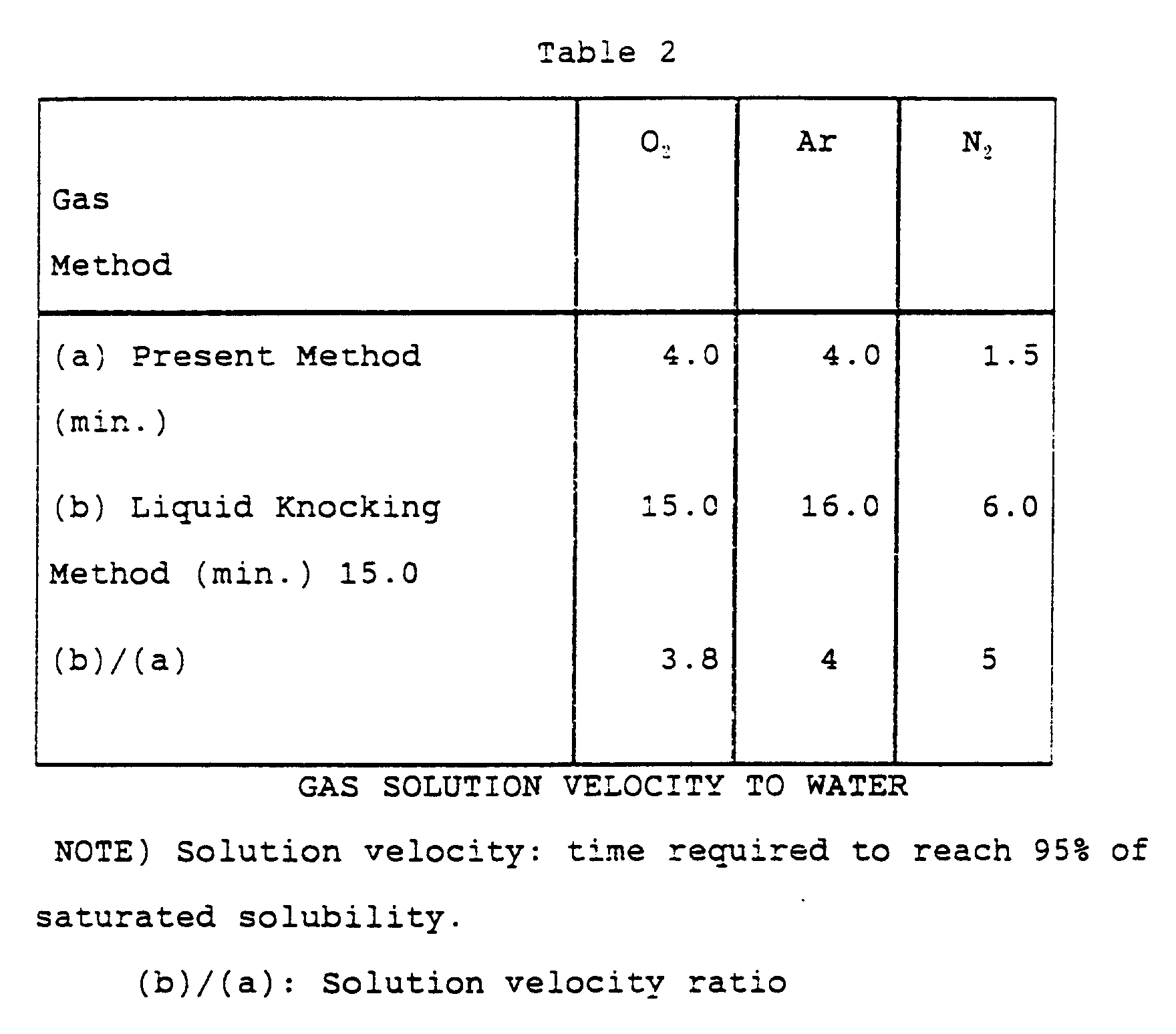
The results obtained are given in Table 2 below.
Sample gases used were oxygen, argon, and nitrogen.
As apparent from Table 2, a larger number of finer
bubbles were formed in the liquid knocking method used
in this embodiment than in the bubbling with a small
tube. As a result, the solution velocity was larger
than in the bubbling. In this Embodiment (I-2), no
such effect was obtained that the bubbles became fine
due to vibration of the small tube (a nozzle) as in
Embodiment I-1. Accordingly, this embodiment was less
significant than Embodiment I-1 on the effect of
improving the solution velocity. However, the solution
velocity was superior by 3-5 times to that in the
bubbling method.
Subsequently, another test was conducted. More
specifically, the water was replaced by octane as the
liquid phase, into which argon gas was dissolved. At
the vibrator driving voltage of 300 Vp-p, the bubbles
were released out of octane. With this respect, the
experiment was conducted at the vibrator driving
voltage of 200 Vp-p. Fig. 7 shows a dissolution
characteristic of argon to octane obtained in this
embodiment. The solution velocities were 10 minutes
and 20 minutes with the present method and the liquid
column knocking method (without application of the
vibration wave to the liquid phase), respectively. The
gas solubility had an upper limit, i.e., approximately
95% the saturated solubility with the present
embodiment. It is preferable to dissolve the gas up to
95% the saturated solubility by using the present
method, following which the liquid column knocking may
be used.
In addition, as an example of dissolving gas into
an organic solvent, the dissolution treatment was
conducted by using a light oil and a heavy oil. The
chamber 10 used for treatment had a diameter D of 4 cm.
The gas dissolved was oxygen. The results are given in
Figs. 8 and 9. Fig. 8 shows solution characteristics
of oxygen to the light oil, while Fig. 9 shows solution
characteristics of oxygen to the heavy oil. With the
apparatus according to this embodiment, the solution
velocities were six times and thirteen times for the
light oil and heavy oil, respectively, as high as those
in the bubbling.
The above mentioned results indicated
experimentally that the method embodying the present
invention is well applicable to the organic solvents.
Embodiment I-3
A gas dissolution test was conducted with the
liquid treating apparatus illustrated in Fig. 10A. The
liquid treating apparatus of this embodiment comprises
a frequency optimizing arithmetic unit 18 in place of
the oscilloscope 17 in Fig. 3A. In addition, a current
probe 19 is arranged between the frequency optimizing
arithmetic unit 18 and the Q circuit 15 to detect the
vibration current supplied from the Q circuit 15 to the
vibrators 11. Other components and parts are similar
to these described in conjunction with Figs. 3A through
3C. This apparatus has a feedback function for
controlling the vibration frequency of the vibrators 11
to ensure proper resonance conditions by means of
monitoring the amplitude by vibration in the chamber 10
as well as the current flowing through the vibrators
11.
The test was conducted by using the above
mentioned liquid treating apparatus illustrated in Fig.
10A. The amplitude by vibration of the chamber 10 was
increased when the chamber 10 was in the resonance
state. The maximum amplitude by vibration was obtained
in the chamber 10 and the smallest current was supplied
to the vibrators 11 when the chamber 10 was in the
resonance state. Accordingly, it was possible to keep
the resonance condition by means of detecting the
amplitude and the current and adjusting them. In this
embodiment, it was possible to keep the resonance
condition even if the propagation velocity of the
vibration wave through the liquid phase is changed with
temperature of or the amount of the dissolved gas in
the liquid phase.
As mentioned above, the liquid treating method and
the liquid treating apparatus according to the present
invention allowed the gas dissolved into the liquid up
to the saturated solubility for a shorter period of
time as compared with conventional ones.
Embodiment II-1 (Liquid Modification)
A gas dissolution test was conducted with the
liquid treating apparatus illustrated in Fig. 17A.
The chamber 10 comprises a liquid containing unit
10a and a gas filling unit 10b, which chamber 10 is
made of quartz and is formed into a sphere with outer
and inner diameters of 54 mm and 50 mm, respectively.
A single pair (two) of the vibrators 11 were disposed
on both sides of the chamber 10, symmetrically with
respect to the center thereof.
Pure water containing no dissolved gas was charged
in the above mentioned chamber. A gas was released
into the pure water out of a small tube (having an
inner diameter of 500 µm). With the vibrator 11
driving voltage of 1500 Vp-p, an output voltage of the
oscillator 13 was 3.2 Vp-p while an output voltage of
the amplifier 14 was 120 Vp-p. The temperature of the
treated water was controlled from outside the chamber
10.
A strong vibration wave was generated in the
chamber 10 when the vibrators 11 were operated at the
resonance frequency f (f = V/D) determined according to
the chamber diameter D and the propagation velocity V
of the vibration wave in the water. The strong
vibration wave caused the bubbles to be sucked into the
center of the liquid containing unit 10a shaped in the
sphere. Continuous introduction of the bubbles allowed
constant formation of a strong vibration wave field
where the bubbles are trapped. In addition, it is
possible in this apparatus to adjust a ratio of the
modified water(the water improving the liquid quality)
in the chamber 10 by increasing or decreasing the
treatment time.
Embodiment II-2 (Liquid Modification)
Fig. 18 shows another configuration of the liquid
treating apparatus. This apparatus is similar to the
one illustrated in Fig. 17A except that a liquid column
was knocked against the liquid surface of the water
within the liquid containing unit 10a, which water is
circulated by a pump to form bubbles, and that a
temperature of the treated water was controlled by
means of controlling the temperature of the circulated
water. Such liquid column knocking method has
advantages of effective cooling achieved and smaller
bubbles (fine bubbles) obtained.
Embodiment II-3 (Liquid Modification)
Fig. 19 shows yet another configuration of the
liquid treating apparatus. This apparatus is similar
to the one illustrated in Fig. 17A except that the
treated water was circulated through the cooling
apparatus 21 with the purpose of the temperature
controlling. This apparatus has an advantage of a
higher cooling efficiency over the apparatus
illustrated in Fig. 17A.
Embodiment II-4 (Liquid Modification)
Fig. 20 shows yet another configuration of the
liquid treating apparatus. The liquid treating
apparatus of this embodiment comprises a frequency
optimizing arithmetic unit 18 in place of the
oscilloscope 17 in Fig. 17A. In addition, a current
probe 19 is arranged between the vibrators 11 and the
transformer 15' to detect the vibration current
supplied from the transformer 15' to the vibrators 11.
Other components and parts are similar to these
described in conjunction with Fig. 17A.
This apparatus has a feedback function for
controlling the vibration frequency of the vibrators 11
to ensure proper resonance conditions by means of
monitoring the amplitude by vibration in the chamber 10
detected by the microphone 16 as well as the current
flowing through the vibrators 11.
Tests with this liquid treating apparatus showed
that the maximum voltage level was obtained from the
microphone 16 and the smallest current was supplied to
the vibrators 11 when the chamber 10 was in the
resonance condition.
It was possible to maintain the resonance
condition of the chamber 10 by means of detecting the
amplitude by vibration in the chamber 10 and the
current flowing through the vibrators 11 to adjust them
by using the frequency optimizing arithmetic unit 18.
It was possible to keep the resonance condition even if
the propagation velocity of the vibration wave through
the liquid phase is changed with temperature of or the
amount of the dissolved gas in the liquid phase.
Embodiment II-5
Figs. 21A and 21B show an exemplified method of
keeping the resonance condition. Fig. 21A shows a
structure of the apparatus while Fig. 21B shows a
schematic step of the operation carried out by the
apparatus.
A controller illustrated in Fig. 21A comprises a
high-speed switch 101 connected to either the vibrator
100. The high-speed switch 101 has a detection circuit
for detecting the vibration waves and an application
circuit for applying the vibration wave. The vibrator
100 produces a voltage in response to reception of the
vibration wave. This voltage is detected by the
vibration wave detector 102. The high-speed switch 101
is connected to an applied voltage output circuit 103.
The applied voltage output circuit 103 applies the
driving voltage to the vibrator 100. In addition, the
controller comprises timers 1 and 2. The timers are
used to turn the switch between the detection circuit
and the application circuit over a short period to
produce the vibration waves.
A controlling operation is described now.
With the high-speed switch 101 connected to the
detection circuit, the opposing vibrator is forced to
generate an vibration wave. This vibration wave is
detected through the vibrator 100 by the vibration wave
detector 102 (#100). The timers 1 and 2 start
operation at the timing when the vibration wave is
detected (#012, #104). At the same time, the vibration
wave detector 102 supplies a switching signal to the
high-speed switch 101. The high-speed switch turns its
internal switch to the application circuit in response
to this switching signal (#106).
After elapsing the time set in the timer 1, the
applied voltage output circuit 103 produces an applied
voltage (#108). This output voltage is supplied to the
vibrator 100 through the high-speed switch 101. The
vibrator 100 produces an vibration wave in response to
this output voltage.
After elapsing the time set in the timer 2, the
high-speed switch 101 turns its internal switch to the
detection circuit in response to the switching signal
supplied from the timer 2 (#110). This results in the
condition where the incoming vibration wave can be
detected. The resonance condition can be kept by means
of repeating the above mentioned control flow.
In this event, the controller connected to the
vibrator 100 may be associated with each vibrator to
generate the vibration waves simultaneously by these
vibrators for the above mentioned control flow.
Alternatively as mentioned above, the vibration wave
may be generated by either one of the vibrators. The
incoming vibration wave may be detected by the other
vibrator to initiate the control flow.
Embodiment II-6
Fig. 22A shows a liquid treating apparatus
according to another embodiment of the present
invention. This apparatus has a function of
automatically introducing deaerated water into the
apparatus, that is discharged after modification
treatment.
A schematic operation of this apparatus is
described with reference to Figs. 22A and 22B. Fig.
22A shows a structure of the apparatus while Fig. 22B
shows a schematic step of the operation carried
thereby.
A suction pump is driven with only a valve B4
"opened", the water treating unit is subjected to
deaeration in which the modification treatment is to be
conducted (step 1). Next, a valve B1 is "opened" (Step
2). This makes the deaerated water in the tank flow
into the water treating unit. Subsequently, a water
level detector detects that a predetermined volume of
water is introduced into the water treating unit. In
response to this detection, all valves communicated
with the water treating unit (in this embodiment,
valves B4 and B1) are "closed" to stop the suction pump
(Step 3).
Then, the valve B3 is "opened" to introduce a gas
such as oxygen or argon for use in modifying the water.
Water modification is conducted by using the resonance
of the vibration waves applied by the vibrators (Step
4).
This treatment is continued for a certain period,
following which application of the vibration waves is
stopped (Step 5). The valve B4 is "opened" to
discharge the water improving the liquid water through
the valve B2.
This operational flow permits automatic
modification of deaerated water. In this embodiment,
the liquid treating apparatus comprises a main
controller (not shown) to open/close the valves, to
drive and control the suction pump, and process, for
example, results of the water level detection for the
water treating unit and the tank. To control the
temperature of the treated water or control the bubble
introducing device may be achieved by using any of the
above mentioned aspects.
Embodiment II-7 (Liquid Modification)
Fig. 23A shows a liquid treating apparatus
according to another embodiment of the present
invention. This apparatus is similar in structure and
operation to the apparatus described in Embodiment II-6
except that it has a function of deaeration in the
water treating unit. Accordingly, description of such
parts and components are omitted. For the detailed
operation, see steps illustrated in Fig. 23B.
Embodiment II-8 (Liquid Modification)
Fig. 24 shows a liquid treating apparatus
according to yet another embodiment of the present
invention. This apparatus is of the type of treating
liquid through continuous flow. This apparatus
supplies the deaerated water to the water treating unit
at a constant flow rate under control by a flow rate
controller. The water was subjected to the
modification treatment in the water treating unit for a
predetermined period, following which the modified
water is discharged. See the above mentioned
embodiments for other structure and operation.
As mentioned above, it was possible to modify the
water effectively by using the above mentioned
modification method and modification apparatus.
Properties of Modified Water
Properties of the water, which was treated by
using the apparatus in Embodiment II-1 (using oxygen),
were determined. For the purpose of comparison, a pure
water saturated with oxygen (water after deaeration of
the dissolved gas and saturated with was used
considering effects of the dissolved gas. The water
used was a superpose water (specific resistance: 18 MΩ·
cm).
Property 1: Effect on Lactobacillus Growth
A mixture of water (5 cc) and milk (15 cc) was
placed in a Petri dish of 9 cm in diameter. Yogurt (3
cc) was dropped at the center thereof, which the yogurt
spread to a circle of 2.0-2.1 cm in diameter.
Considering that the diameter of the yogurt would be
increased, the content of the Petri dish was stood at
that state to observe the growth of the yogurt.
Modification of water was conducted under the
conditions: treatment time T = 1 hour, gas used; O2,
vibrator driving voltage; V = 800 Vp-p, and chamber
inner diameter; D = 5 cm.
The results are given in Fig. 25. These results
revealed that Lactobacillus grows actively with the
modified water mixed.
Property 2: Effect on Absorption of Soy Beans
Soy beans were dipped overnight in water, and
absorptivity was determined according to change in
weight of the soy beans. In this test, fifteen soy
beans (6.2 g) were used, which were of approximately
uniform size. Modification of water was conducted
under the conditions: treatment time T = 1 hour, gas
used; O2, vibrator driving voltage; V = 800 Vp-p, and
chamber inner diameter; D = 5 cm. The results are
given in Fig. 25. These results revealed that the
modified water was absorbed more.
Property 3: Effect on Growth of Soy Beans
Vermiculite of 60 g was placed in a container of
170 x 170 x 30 mm and was allowed to absorb water (200
g), on which thirty soy beans were placed. The
container was stood in a dark room at 25°C except for
when picked up to absorb water (100 g) after 7 days.
The growth rate of the soy beans on each water was
determined according to "length" and "thickness" after
10 days. Modification of water was conducted under the
conditions: treatment time T = 1 hour, gas used; O2,
vibrator driving voltage; V = 800 Vp-p, and chamber
inner diameter; D = 5 cm. The results are given in
Fig. 25.
As apparent from Figs. 27 and 28, it was revealed
that the soy beans grew well with the modified water
(the water improving the liquid quality).
Property 4: Effect on Water Retention of Skin
A mixture of water (3 cc) and cosmetic liquid (0.1
cc) was applied to the back of the hand over 1 minute
to determine change with time of water retained in the
skin. The water retention of the skin was obtained by
using a device for obtaining it according to electric
conductivity of the skin. Modification of water was
conducted under the conditions: treatment time T = 1
hour, gas used; O2, vibrator driving voltage; V = 800
Vp-p, and chamber inner diameter; D = 5 cm. The results
are given in Fig. 29. The results revealed that, as
shown in Fig. 29, the higher water retention can be
provided with the modified water.
Property 5: Effect on Durability of Cut Flowers
A vein of a rose was cut perpendicularly and was
dipped into water. At this state, petals were
observed. Modification of water was conducted under
the conditions: treatment time T = 1 hour, gas used; O2,
vibrator driving voltage; V = 800 Vp-p, and chamber
inner diameter; D = 4.5 cm. As a result, the petals
were fallen off after 7 days with the untreated water.
On the other hand, the petals were kept well after 12
days with the modified water.
As mentioned above, according to the described
embodiments of the invention, there is provided with
a liquid treating method in which bubbles of a gas are
formed in a liquid phase and are compressed by using
collision of the opposing vibration waves to dissolve
the bubbles into the liquid phase.
in addition, according to the described
embodiments of the invention, there is provided with
a liquid treating apparatus comprising a chamber for
holding or storing a liquid in, a vibrator for
applying a vibration wave to the liquid, and bubble
forming means for forming bubbles of a gas in the
liquid. The bubbles are dissolved into the liquid
through compression of bubbles by using collision of
vibration waves in the chamber.
Accordingly, the described embodiments of the
invention allow for effective dissolution of gases
into a liquid phase in various fields requiring
dissolution of a gas including hydroponic, cultural,
chemical, and enzyme industries as well as for
treating water, fuel, and exhaust gas. The present
invention can improve efficiency of hydroponic
cultivation, enhance effective feeding of oxygen to
cultured fishes, shells and so on in a farm, and
reduce a fermentation period required to fermentate
sake or the like. As a result, it becomes possible to
reduce instrument costs, improve treatment efficiency,
and increase reaction speed in these fields.
It has been revealed experimentally that the
water
modified according to a method embodying the present
invention has different properties from those of the
untreated water. Accordingly, it is possible to
provide a method of allowing effective modification of
water around a high-temperature, high-field formed as a
result of collision of the strong vibration waves on
the bubbles formed by superposing the vibration waves.
In addition, there is provided with an apparatus
which comprises a chamber for holding or storing a
liquid in, a vibrator for applying an vibration wave
to the liquid, bubble forming means for forming bubbles
of a gas in the liquid, and a temperature controller
for water treatment, and which allows effective
modification of water around a high-temperature, high-field
formed as a result of collision of the strong
vibration waves on the bubbles formed by superposing
the vibration waves.
As mentioned above, according to the described
embodiments of the invention, a liquid can be modified
effectively only by with a chamber, a liquid, a gas,
vibrators, and a temperature controller. In addition,
it becomes possible to adjust the degree of modification
based on the vibrator amplitude, treatment time, and
types of the gas introduced.
From the invention thus described, it will be
obvious that the invention is only limited by the scope of
the following claims.