EP0660459B1 - Multiple flat terminal plug - Google Patents
Multiple flat terminal plug Download PDFInfo
- Publication number
- EP0660459B1 EP0660459B1 EP94119099A EP94119099A EP0660459B1 EP 0660459 B1 EP0660459 B1 EP 0660459B1 EP 94119099 A EP94119099 A EP 94119099A EP 94119099 A EP94119099 A EP 94119099A EP 0660459 B1 EP0660459 B1 EP 0660459B1
- Authority
- EP
- European Patent Office
- Prior art keywords
- sleeve
- flat connector
- sleeve body
- openings
- function
- Prior art date
- Legal status (The legal status is an assumption and is not a legal conclusion. Google has not performed a legal analysis and makes no representation as to the accuracy of the status listed.)
- Expired - Lifetime
Links
Images
Classifications
-
- H—ELECTRICITY
- H01—ELECTRIC ELEMENTS
- H01R—ELECTRICALLY-CONDUCTIVE CONNECTIONS; STRUCTURAL ASSOCIATIONS OF A PLURALITY OF MUTUALLY-INSULATED ELECTRICAL CONNECTING ELEMENTS; COUPLING DEVICES; CURRENT COLLECTORS
- H01R13/00—Details of coupling devices of the kinds covered by groups H01R12/70 or H01R24/00 - H01R33/00
- H01R13/46—Bases; Cases
- H01R13/52—Dustproof, splashproof, drip-proof, waterproof, or flameproof cases
- H01R13/5205—Sealing means between cable and housing, e.g. grommet
-
- H—ELECTRICITY
- H01—ELECTRIC ELEMENTS
- H01R—ELECTRICALLY-CONDUCTIVE CONNECTIONS; STRUCTURAL ASSOCIATIONS OF A PLURALITY OF MUTUALLY-INSULATED ELECTRICAL CONNECTING ELEMENTS; COUPLING DEVICES; CURRENT COLLECTORS
- H01R13/00—Details of coupling devices of the kinds covered by groups H01R12/70 or H01R24/00 - H01R33/00
- H01R13/02—Contact members
- H01R13/04—Pins or blades for co-operation with sockets
-
- H—ELECTRICITY
- H01—ELECTRIC ELEMENTS
- H01R—ELECTRICALLY-CONDUCTIVE CONNECTIONS; STRUCTURAL ASSOCIATIONS OF A PLURALITY OF MUTUALLY-INSULATED ELECTRICAL CONNECTING ELEMENTS; COUPLING DEVICES; CURRENT COLLECTORS
- H01R13/00—Details of coupling devices of the kinds covered by groups H01R12/70 or H01R24/00 - H01R33/00
- H01R13/46—Bases; Cases
- H01R13/502—Bases; Cases composed of different pieces
-
- H—ELECTRICITY
- H01—ELECTRIC ELEMENTS
- H01R—ELECTRICALLY-CONDUCTIVE CONNECTIONS; STRUCTURAL ASSOCIATIONS OF A PLURALITY OF MUTUALLY-INSULATED ELECTRICAL CONNECTING ELEMENTS; COUPLING DEVICES; CURRENT COLLECTORS
- H01R13/00—Details of coupling devices of the kinds covered by groups H01R12/70 or H01R24/00 - H01R33/00
- H01R13/46—Bases; Cases
- H01R13/52—Dustproof, splashproof, drip-proof, waterproof, or flameproof cases
- H01R13/5216—Dustproof, splashproof, drip-proof, waterproof, or flameproof cases characterised by the sealing material, e.g. gels or resins
-
- H—ELECTRICITY
- H01—ELECTRIC ELEMENTS
- H01R—ELECTRICALLY-CONDUCTIVE CONNECTIONS; STRUCTURAL ASSOCIATIONS OF A PLURALITY OF MUTUALLY-INSULATED ELECTRICAL CONNECTING ELEMENTS; COUPLING DEVICES; CURRENT COLLECTORS
- H01R2107/00—Four or more poles
-
- H—ELECTRICITY
- H01—ELECTRIC ELEMENTS
- H01R—ELECTRICALLY-CONDUCTIVE CONNECTIONS; STRUCTURAL ASSOCIATIONS OF A PLURALITY OF MUTUALLY-INSULATED ELECTRICAL CONNECTING ELEMENTS; COUPLING DEVICES; CURRENT COLLECTORS
- H01R24/00—Two-part coupling devices, or either of their cooperating parts, characterised by their overall structure
- H01R24/20—Coupling parts carrying sockets, clips or analogous contacts and secured only to wire or cable
Definitions
- the invention relates to a multiple tab connector according to the preamble of claim 1; (see US-A-5 026 304).
- From DE-PS 29 00 763 is a liquid-tight, with a flat connector equipped implementation has become known, intended for use in a housing wall bore and their tabs are housed in the housing and electrical equipment encapsulated with resin connected.
- the implementation is as elastic cup formed on the front closed is.
- the closed end wall of the cup contains an integral one on the inside and tapered cylindrical part in which the Flat connector is guided.
- Such a flat plug has only one plug element.
- the object of the invention is a flat plug of the beginning to create the type mentioned, in which several tab connector elements can be provided.
- a sleeve body made of insulating material is in a sleeve made of metal and a sub-area inside the sleeve between the sleeve body and the adjacent one End edge of the sleeve poured out with casting resin, so that a dense multiple flat connector is formed.
- the through openings essentially have one rectangular cross section, the one the dimensions of a Corresponding narrowing of the tab connector element for guidance of the tab connector element.
- each through opening has a constriction, which in a particularly advantageous manner compared to the through opening is eccentric so a connection cable is on the flat connector element can be clamped.
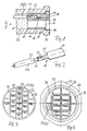
- a metallic sleeve 10 has an interior 11, in which a sleeve body 12 is inserted.
- the interior 11 is cylindrical and has on its one, in the Drawing right end of a gradation 13, by which formed an area 14 with an enlarged diameter is.
- the sleeve body 12 has a cylindrical section 15, which is adjoined by a cylindrical section 16, that in the assembled state in section 14 engages with an enlarged diameter, whose Flange edge on step 13 comes to rest.
- the sleeve body 12 has a plurality of openings 17 which, as can be seen from Figures 3 or 4, one in have a substantially rectangular cross section. Within of the opening 17 there is a constriction 18, which are asymmetrical with respect to the central axis of the opening 17 or is offset or arranged.
- the plug element 19, the perspective in Figure 2 is shown has essentially one elongated rectangular connector section 20 to the a connecting tab 21 connects, the free end bendable Has clamping lugs 22 with which the soul 23rd a preferably insulated conductor 24 are clamped can.
- the metal sleeve has one on its outer circumference Flange board 27, as shown in Figure 4, a has hexagonal contour with rounded corners 28; it there is of course also the possibility of the flange flange form with a circular contour, whereby only on two diametrically opposed sections a flattening is provided.
- FIGS 29 and 33 now show different arrangements of breakthroughs 17.
- the breakthroughs of Rows 29 and 33 have an approximately triangular cross section have, of the round outer contour of the sleeve body is determined.
- the breakthroughs are the same of rows 30, 31 and 32, which lie on the outer contour, adapted to this outer contour.
- the sleeve body according to the figure 3 would then be similar to the sleeve body 12 of FIG. 1 inserted in a sleeve made of metal and potted therein will.
- the insulation with the 24/25 conductor then takes effect into the interior of the sleeve body at least partially, which is not shown in Figure 1.
- Figure 4 shows a total of only four rows of openings with the reference numbers 34, 35, 36 and 37.
- the breakthroughs the middle rows 35 and 36 are parallel to each other, whereas the breakthroughs and especially the Constrictions perpendicular to the constrictions in rows 35 and 36 are aligned.
Description
Die Erfindung betrifft einen Vielfach-Flachstecker gemäß dem Oberbegriff des Anspruches 1 ; (vgl. US-A-5 026 304).The invention relates to a multiple tab connector according to the preamble of claim 1; (see US-A-5 026 304).
Aus der DE-PS 29 00 763 ist eine flüssigkeitsdichte, mit einem Flachstecker ausgerüstete Durchführung bekannt geworden, die zum Einsatz in eine Gehäusewandbohrung bestimmt ist und deren Flachstecker an im Gehäuse untergebrachten und mit Gießharz vergossenen elektrischen Einrichtungen angeschlossen ist. Die Durchführung ist als elastischer Becher ausgebildet, der auf seiner Stirnseite geschlossen ist. Die geschlossene Stirnwand des Bechers enthält auf seiner Innenseite einen einstückig angeformten und konisch verjüngten zylindrischen Teil, in dem der Flachstecker geführt ist.From DE-PS 29 00 763 is a liquid-tight, with a flat connector equipped implementation has become known, intended for use in a housing wall bore and their tabs are housed in the housing and electrical equipment encapsulated with resin connected. The implementation is as elastic cup formed on the front closed is. The closed end wall of the cup contains an integral one on the inside and tapered cylindrical part in which the Flat connector is guided.
Ein derartiger Flachstecker besitzt lediglich ein Stekkerelement. Such a flat plug has only one plug element.
Aufgabe der Erfindung ist es, einen Flachstecker der eingangs genannten Art zu schaffen, bei dem mehrere Flachsteckerelemente vorgesehen sein können.The object of the invention is a flat plug of the beginning to create the type mentioned, in which several tab connector elements can be provided.
Diese Aufgabe wird erfindungsgemäß gelöst durch die kennzeichnenden Merkmale des Anspruches 1.This object is achieved by the characterizing Features of claim 1.
Danach ist ein Hülsenkörper aus isolierendem Material in eine Hülse aus Metall eingesetzt und ein Teilbereich innerhalb der Hülse zwischen dem Hülsenkörper und der benachbarten Stirnkante der Hülse mit Gießharz ausgegossen, so daß hierdurch ein dichter Vielfach-Flachstecker gebildet ist.After that, a sleeve body made of insulating material is in a sleeve made of metal and a sub-area inside the sleeve between the sleeve body and the adjacent one End edge of the sleeve poured out with casting resin, so that a dense multiple flat connector is formed.
Die Durchgangsöffnungen besitzen im wesentlichen einen rechteckigen Querschnitt, der eine den Abmessungen eines Flachsteckerelementes entsprechende Verengung zur Führung des Flachsteckerelementes aufweist.The through openings essentially have one rectangular cross section, the one the dimensions of a Corresponding narrowing of the tab connector element for guidance of the tab connector element.
Gemäß einer weiteren vorteilhaften Ausgestaltung der Erfindung besitzt jede Durchgangsöffnung eine Verengung, die in besonders vorteilhafter Weise gegenüber der Durchgangsöffnung exzentrisch ist, damit ein Anschlußkabel an dem Flachsteckerelement angeklemmt werden kann.According to a further advantageous embodiment of the invention each through opening has a constriction, which in a particularly advantageous manner compared to the through opening is eccentric so a connection cable is on the flat connector element can be clamped.
Weitere vorteilhafte Ausgestaltungen und Verbesserungen der Erfindung sind den weiteren Unteransprüchen zu entnehmen.Further advantageous refinements and improvements the invention can be found in the further subclaims.
Anhand der Zeichnung, in der mehrere Ausführungsbeispiele der Erfindung dargestellt sind, sollen die Erfindung sowie weitere vorteilhafte Ausgestaltungen und Verbesserungen der Erfindung näher erläutert und beschrieben werden. Using the drawing in which several embodiments the invention are shown, the invention and further advantageous refinements and improvements the invention are explained and described in more detail.
Es zeigen:
- Figur 1
- eine Teilschnittansicht durch einen erfindungsgemäßen Vielfach-Flachstecker,
- Figur 2
- eine perspektivische Ansicht eines Flachsteckerelementes mit angeklemmten Draht,
- Figur 3
- eine Aufsicht gemäß Pfeilrichtung III auf einen Hülsenkörper der Figur 1 in einer ersten Ausführung, unvergossen, und
- Figur 4
- eine Aufsicht gemäß Pfeilrichtung IV auf eine andere Ausführungsform des Hülsenkörpers mit Hülse.
- Figure 1
- 2 shows a partial sectional view through a multiple tab connector according to the invention,
- Figure 2
- 2 shows a perspective view of a flat plug element with clamped wire,
- Figure 3
- a plan view in the direction of arrow III on a sleeve body of Figure 1 in a first embodiment, potted, and
- Figure 4
- a plan according to arrow direction IV on another embodiment of the sleeve body with sleeve.
Eine metallische Hülse 10 besitzt einen Innenraum 11, in
dem ein Hülsenkörper 12 eingesetzt ist. Der Innenraum 11
ist zylindrisch und besitzt an seinem einen, in der
Zeichnung rechts befindlichen Ende eine Stufung 13, durch
welche ein Bereich 14 mit erweitertem Durchmesser gebildet
ist.A
Der Hülsenkörper 12 besitzt einen zylindrischen Abschnitt
15, an den sich ein zylindrischer Abschnitt 16 anschließt,
der im montierten Zustand in den Abschnitt 14
mit erweitertem Durchmesser eingreift, wobei dessen
Flanschrand auf der Stufung 13 zu liegen kommt.The sleeve body 12 has a
Der Hülsenkörper 12 besitzt mehrere Durchbrüche 17, die,
wie aus den Figuren 3 oder 4 ersichtlich ist, einen im
wesentlichen rechteckigen Querschnitt aufweisen. Innerhalb
des Durchbruches 17 befindet sich eine Verengung 18,
die bezogen auf die Mittelachse des Durchbruches 17 unsymmetrisch
bzw. versetzt angebracht oder angeordnet ist. The sleeve body 12 has a plurality of openings 17 which,
as can be seen from Figures 3 or 4, one in
have a substantially rectangular cross section. Within
of the opening 17 there is a
Durch die Verengung 18 wird ein Flachsteckerelement 19
mit dem Steckerabschnitt 20, siehe Figur 2 hindurchgesteckt.
Das Steckerelement 19, das in Figur 2 perspektivisch
dargestellt ist, besitzt einen im wesentlichen
langgestreckt rechteckigen Steckerabschnitt 20, an den
eine Anschlußfahne 21 anschließt, deren freies Ende zubiegbare
Klemmfahnen 22 aufweist, mit denen die Seele 23
eines vorzugsweise isolierten Leiters 24 eingeklemmt werden
kann.Due to the
Nachdem das Steckerelement 19 mit dem Leiter 24 verbunden
ist, wird es von hinten, gemäß Pfeilrichtung III oder IV,
in den Durchbruch 17 durch die Verengung 18 hindurchgeschoben.
Es besteht dabei auch die Möglichkeit, daß dann,
wenn der Durchbruch 17 entsprechend bemessen ist, auch
die Isolierung 25 des Leiters 24 in den Durchbruch 17
eingeschoben werden kann, wie beispielsweise in Figur 3
oder Figur 4 angedeutet ist. Danach wird der zylindrische
Raum 11 bis zum inneren Ende des zylindrischen Abschnittes
15 des Hülsenkörpers 12 mit Gießharz 26 ausgegossen.After the
Die Hülse aus Metall besitzt an ihrem Außenumfang einen
Flanschbord 27, der wie in Figur 4 dargestellt ist, eine
sechseckige Kontur mit abgerundeten Ecken 28 aufweist; es
besteht natürlich auch die Möglichkeit, den Flanschbord
mit einer kreisförmigen Kontur auszubilden, wobei lediglich
an zwei diametral sich gegenüberliegenden Abschnitten
jeweils eine Abflachung vorgesehen ist.The metal sleeve has one on its outer
Die Figuren 3 und 4 zeigen nun unterschiedliche Anordnungen der Durchbrüche 17. In Figur 3 sind insgesamt vier Reihen 29, 30, 31, 32 und 33 zueinander parallel verlaufender Durchbrüche vorgesehen, wobei die Durchbrüche der Reihen 29 und 33 einen etwa dreieckförmigen Querschnitt aufweisen, der von der runden Außenkontur des Hülsenkörpers bestimmt ist. In gleicher Weise sind die Durchbrüche der Reihen 30, 31 und 32, die an der Außenkontur liegen, dieser Außenkontur angepaßt. Der Hülsenkörper gemäß Figur 3 würde dann ähnlich wie der Hülsenkörper 12 der Figur 1 in eine Hülse aus Metall eingesetzt und darin vergossen werden. Die Isolierung mit dem Leiter 24/25 greift dann in das Innere des Hülsenkörpers wenigstens teilweise ein, was in der Figur 1 nicht dargestellt ist.Figures 3 and 4 now show different arrangements of breakthroughs 17. There are a total of four in FIG Rows 29, 30, 31, 32 and 33 run parallel to each other Breakthroughs provided, the breakthroughs of Rows 29 and 33 have an approximately triangular cross section have, of the round outer contour of the sleeve body is determined. The breakthroughs are the same of rows 30, 31 and 32, which lie on the outer contour, adapted to this outer contour. The sleeve body according to the figure 3 would then be similar to the sleeve body 12 of FIG. 1 inserted in a sleeve made of metal and potted therein will. The insulation with the 24/25 conductor then takes effect into the interior of the sleeve body at least partially, which is not shown in Figure 1.
Die Figur 4 zeigt insgesamt nur vier Reihen von Durchbrüchen
mit den Bezugsziffern 34, 35, 36 und 37. Die Durchbrüche
der mittleren Reihen 35 und 36 liegen parallel zueinander,
wogegen die Durchbrüche und insbesondere die
Verengungen senkrecht zu den Verengungen der Reihen 35
und 36 ausgerichtet sind.Figure 4 shows a total of only four rows of openings
with the
Es lassen sich noch sehr viele Anordnungen von Durchbrüchen denken, abhängig von der erforderlichen Anzahl und der Größe der einzusetzenden Flachsteckerelemente.There are still many arrangements of breakthroughs think depending on the required number and the size of the tab connector elements to be used.
Claims (4)
- Multi-function flat connector with a sleeve body which has axially parallel through openings for receiving cable conductors connected to flat connector elements,
characterised in that the sleeve body (12) of insulating material is inserted in a sleeve (10) of metal, wherein the sleeve body (12), whose length is less than that of the sleeve (10), in the assembled state is situated with its end on the cable side approximately in the plane of a front face of the sleeve (10), whereas the other end of the sleeve body (12) is situated within the sleeve (10) at a distance from its front edge, and that the cup space thus formed is filled with casting resin. - Multi-function flat connector according to claim 1, characterised in that the through openings (17) essentially have a rectangular cross-section which has a narrowing (18), corresponding to the dimensions of the flat connector element (19), for guiding the flat connector element (19).
- Multi-function flat connector according to claim 2, characterised in that the through openings (17) have a narrowing (18) which is unsymmetrical in relation to the centre axis of the through openings, so that the clamping point of the flat connector element (19) fits into the corresponding through opening.
- Multi-function flat connector according to one of the preceding claims,
characterised in that in the area on the cable side the sleeve body (12) has a flange edge (16) arranged on the outer periphery and projecting therefrom and that the sleeve (10) has an offset (13) into which approximately fits the flange edge.
Applications Claiming Priority (2)
| Application Number | Priority Date | Filing Date | Title |
|---|---|---|---|
| DE4341958A DE4341958A1 (en) | 1993-12-09 | 1993-12-09 | Multiple flat plug |
| DE4341958 | 1993-12-09 |
Publications (3)
| Publication Number | Publication Date |
|---|---|
| EP0660459A2 EP0660459A2 (en) | 1995-06-28 |
| EP0660459A3 EP0660459A3 (en) | 1996-07-31 |
| EP0660459B1 true EP0660459B1 (en) | 1998-09-23 |
Family
ID=6504546
Family Applications (1)
| Application Number | Title | Priority Date | Filing Date |
|---|---|---|---|
| EP94119099A Expired - Lifetime EP0660459B1 (en) | 1993-12-09 | 1994-12-03 | Multiple flat terminal plug |
Country Status (2)
| Country | Link |
|---|---|
| EP (1) | EP0660459B1 (en) |
| DE (2) | DE4341958A1 (en) |
Families Citing this family (8)
| Publication number | Priority date | Publication date | Assignee | Title |
|---|---|---|---|---|
| JP3730380B2 (en) * | 1997-10-09 | 2006-01-05 | 矢崎総業株式会社 | Waterproof connector and manufacturing method thereof |
| DE19858111C2 (en) * | 1998-12-16 | 2002-05-02 | Andreas Aschenbrenner | Sealed connector and process for its manufacture |
| DE10034501C1 (en) * | 2000-07-15 | 2001-11-29 | Lumberg Karl Gmbh & Co | Electrical plug connector has grip body as one-piece component of contact bearer with channel for inserting insulated braids of connecting cable crossing contact channels obliquely |
| DE10034503C2 (en) * | 2000-07-15 | 2003-01-30 | Lumberg Karl Gmbh & Co | Electrical connector |
| DE10034502C2 (en) * | 2000-07-15 | 2002-10-31 | Lumberg Karl Gmbh & Co | Electrical connector |
| JP2002093515A (en) | 2000-09-11 | 2002-03-29 | Yazaki Corp | Waterproof connector |
| DE10239018A1 (en) * | 2002-08-20 | 2004-03-04 | Ghw Grote & Hartmann Gmbh | Electrical connector for electronic circuit boards, has contacts within plastic housing that is filled with moulding resin to provide seal |
| DE102015004486B3 (en) * | 2015-04-07 | 2016-06-30 | Rosenberger Hochfrequenztechnik Gmbh & Co. Kg | Method of making a connector and connector |
Family Cites Families (11)
| Publication number | Priority date | Publication date | Assignee | Title |
|---|---|---|---|---|
| FR688401A (en) * | 1929-01-23 | 1930-08-22 | Felten & Guilleaume Carlswerk | Improvements to contact boxes with plugs for removable cables |
| DE2117323C3 (en) * | 1971-04-08 | 1978-08-31 | Robert Bosch Gmbh, 7000 Stuttgart | Temperature switch |
| GB1496485A (en) * | 1973-12-08 | 1977-12-30 | Crabtree & Co Ltd J A | Electric plugs |
| DE2900763C2 (en) * | 1979-01-10 | 1983-03-03 | Siemens AG, 1000 Berlin und 8000 München | Liquid-tight bushing equipped with a flat plug |
| GB2046533A (en) * | 1979-04-11 | 1980-11-12 | Bunker Ramo | Electrical connectors |
| FR2478884A1 (en) * | 1980-03-18 | 1981-09-25 | Telecommunications Sa | Male coaxial plug - has machined shell and pin which clip over and inside plastics separator locked by plastics split ring or resin fill |
| DE3721304A1 (en) * | 1987-06-27 | 1989-01-05 | Gewerk Eisenhuette Westfalia | MULTI-WIRE LOW CURRENT CABLE, ESPECIALLY FOR ELECTROHYDRAULIC REMOVAL CONTROLS |
| US5026304A (en) * | 1989-12-22 | 1991-06-25 | Amp Incorporated | Connector and connector assembly having improved terminal insertion feature |
| FR2663791A1 (en) * | 1990-06-22 | 1991-12-27 | Tecnoffra | Sealing device for electrical connection cases (boxes) |
| DE4116748C1 (en) * | 1991-05-23 | 1992-10-01 | Leopold Kostal Gmbh & Co Kg, 5880 Luedenscheid, De | Multi-lead electrical coupling component - has sealing material channel and trough extending from plug region to achieve watertightness |
| DE9316521U1 (en) * | 1993-10-28 | 1994-01-05 | Klein Schanzlin & Becker Ag | Liquid and gas-tight cable entry |
-
1993
- 1993-12-09 DE DE4341958A patent/DE4341958A1/en not_active Withdrawn
-
1994
- 1994-12-03 EP EP94119099A patent/EP0660459B1/en not_active Expired - Lifetime
- 1994-12-03 DE DE59406969T patent/DE59406969D1/en not_active Expired - Lifetime
Also Published As
| Publication number | Publication date |
|---|---|
| EP0660459A3 (en) | 1996-07-31 |
| EP0660459A2 (en) | 1995-06-28 |
| DE59406969D1 (en) | 1998-10-29 |
| DE4341958A1 (en) | 1995-06-14 |
Similar Documents
| Publication | Publication Date | Title |
|---|---|---|
| DE3110144C2 (en) | Strain relief for electrical conductors in an electrical connector for non-stripped conductors | |
| DE1465176B2 (en) | ELECTRICAL CONNECTOR ARRANGEMENT CONSISTS OF A SLEEVE ROLLED FROM SHEET METAL TO ACCOMMODATE A PLUG-IN CONTACT PIN | |
| EP0660459B1 (en) | Multiple flat terminal plug | |
| EP0156956A1 (en) | Device to maintain an electric cable in a connection box | |
| DE3028809C2 (en) | Connector arrangement for receiving a flat plug | |
| DE2130888B2 (en) | Coaxial antenna junction box | |
| DE3905024A1 (en) | CONNECTING DEVICE FOR ELECTRICAL CABLES | |
| DE1615655A1 (en) | Electrical connector housing | |
| DE8235771U1 (en) | Electrical active pin contact | |
| EP1382047B1 (en) | Magnet coil arrangement | |
| DE1934795A1 (en) | Protection tube anchor contact | |
| EP0415136B1 (en) | Connector insert for a metallic housing | |
| DE4320539A1 (en) | Line wire connector | |
| DE4115020C3 (en) | Wire end ferrule | |
| EP0155573A1 (en) | Coil bobbin for electrical apparatuses suited for automation | |
| DE102013001828B4 (en) | Shielding element and connector and a method for connecting a cable having a shielding to a connector by means of the Schirmungselements | |
| DE3732576A1 (en) | EXPLOSION-PROTECTED AND / OR FLASH-PROTECTED PLUG-IN | |
| DE4307728C2 (en) | Connectors | |
| DE19746312B4 (en) | Cable termination or cable sleeve | |
| EP0141047A1 (en) | Clamping screws for a strip connector | |
| DE3829486A1 (en) | Contact for electric connections | |
| DE3629874A1 (en) | FLAT CABLE CONNECTOR | |
| DE2413300C3 (en) | ||
| DE102008057473A1 (en) | Cable bushing for implementing electrical cable in e.g. electrical or electronic device, has locking section with non-round cross-section area that is formed such that locking section is non-withdrawable in turned position | |
| DE3838890A1 (en) | Piezoelectric line (cable, lead) |
Legal Events
| Date | Code | Title | Description |
|---|---|---|---|
| PUAI | Public reference made under article 153(3) epc to a published international application that has entered the european phase |
Free format text: ORIGINAL CODE: 0009012 |
|
| AK | Designated contracting states |
Kind code of ref document: A2 Designated state(s): DE FR GB |
|
| PUAL | Search report despatched |
Free format text: ORIGINAL CODE: 0009013 |
|
| RAP1 | Party data changed (applicant data changed or rights of an application transferred) |
Owner name: CEAG SICHERHEITSTECHNIK GMBH |
|
| AK | Designated contracting states |
Kind code of ref document: A3 Designated state(s): DE FR GB |
|
| 17P | Request for examination filed |
Effective date: 19961014 |
|
| GRAG | Despatch of communication of intention to grant |
Free format text: ORIGINAL CODE: EPIDOS AGRA |
|
| 17Q | First examination report despatched |
Effective date: 19971222 |
|
| GRAG | Despatch of communication of intention to grant |
Free format text: ORIGINAL CODE: EPIDOS AGRA |
|
| GRAH | Despatch of communication of intention to grant a patent |
Free format text: ORIGINAL CODE: EPIDOS IGRA |
|
| GRAH | Despatch of communication of intention to grant a patent |
Free format text: ORIGINAL CODE: EPIDOS IGRA |
|
| GRAA | (expected) grant |
Free format text: ORIGINAL CODE: 0009210 |
|
| AK | Designated contracting states |
Kind code of ref document: B1 Designated state(s): DE FR GB |
|
| GBT | Gb: translation of ep patent filed (gb section 77(6)(a)/1977) |
Effective date: 19980925 |
|
| REF | Corresponds to: |
Ref document number: 59406969 Country of ref document: DE Date of ref document: 19981029 |
|
| ET | Fr: translation filed | ||
| PLBE | No opposition filed within time limit |
Free format text: ORIGINAL CODE: 0009261 |
|
| STAA | Information on the status of an ep patent application or granted ep patent |
Free format text: STATUS: NO OPPOSITION FILED WITHIN TIME LIMIT |
|
| 26N | No opposition filed | ||
| REG | Reference to a national code |
Ref country code: GB Ref legal event code: IF02 |
|
| REG | Reference to a national code |
Ref country code: FR Ref legal event code: CD |
|
| PGFP | Annual fee paid to national office [announced via postgrant information from national office to epo] |
Ref country code: GB Payment date: 20131126 Year of fee payment: 20 |
|
| PGFP | Annual fee paid to national office [announced via postgrant information from national office to epo] |
Ref country code: FR Payment date: 20131126 Year of fee payment: 20 |
|
| PGFP | Annual fee paid to national office [announced via postgrant information from national office to epo] |
Ref country code: DE Payment date: 20131230 Year of fee payment: 20 |
|
| REG | Reference to a national code |
Ref country code: DE Ref legal event code: R071 Ref document number: 59406969 Country of ref document: DE |
|
| REG | Reference to a national code |
Ref country code: GB Ref legal event code: PE20 Expiry date: 20141202 |
|
| PG25 | Lapsed in a contracting state [announced via postgrant information from national office to epo] |
Ref country code: GB Free format text: LAPSE BECAUSE OF EXPIRATION OF PROTECTION Effective date: 20141202 |