EP0659923A1 - Réseau de fils de verre et matériau composite renforcé par ledit réseau - Google Patents
Réseau de fils de verre et matériau composite renforcé par ledit réseau Download PDFInfo
- Publication number
- EP0659923A1 EP0659923A1 EP19940403005 EP94403005A EP0659923A1 EP 0659923 A1 EP0659923 A1 EP 0659923A1 EP 19940403005 EP19940403005 EP 19940403005 EP 94403005 A EP94403005 A EP 94403005A EP 0659923 A1 EP0659923 A1 EP 0659923A1
- Authority
- EP
- European Patent Office
- Prior art keywords
- network
- glass
- wires
- composite material
- threads
- Prior art date
- Legal status (The legal status is an assumption and is not a legal conclusion. Google has not performed a legal analysis and makes no representation as to the accuracy of the status listed.)
- Granted
Links
- 239000011521 glass Substances 0.000 title claims abstract description 47
- 239000011208 reinforced composite material Substances 0.000 title 1
- 239000002131 composite material Substances 0.000 claims abstract description 24
- 239000011230 binding agent Substances 0.000 claims abstract description 18
- 238000002844 melting Methods 0.000 claims abstract description 15
- 230000008018 melting Effects 0.000 claims abstract description 15
- 238000000034 method Methods 0.000 claims abstract description 7
- 229920001169 thermoplastic Polymers 0.000 claims abstract description 6
- 239000004416 thermosoftening plastic Substances 0.000 claims abstract description 6
- 239000000463 material Substances 0.000 claims description 10
- 239000000203 mixture Substances 0.000 claims description 5
- 229920000728 polyester Polymers 0.000 claims description 3
- 229920001187 thermosetting polymer Polymers 0.000 claims description 3
- 239000003822 epoxy resin Substances 0.000 claims 1
- 229920000647 polyepoxide Polymers 0.000 claims 1
- 230000003014 reinforcing effect Effects 0.000 claims 1
- 230000002787 reinforcement Effects 0.000 abstract description 11
- 239000000126 substance Substances 0.000 abstract description 2
- 238000004519 manufacturing process Methods 0.000 description 6
- 239000011368 organic material Substances 0.000 description 5
- 238000007596 consolidation process Methods 0.000 description 3
- 238000001816 cooling Methods 0.000 description 3
- 239000012071 phase Substances 0.000 description 3
- 230000008021 deposition Effects 0.000 description 2
- 238000006073 displacement reaction Methods 0.000 description 2
- 238000010438 heat treatment Methods 0.000 description 2
- 238000000465 moulding Methods 0.000 description 2
- 239000011347 resin Substances 0.000 description 2
- 229920005989 resin Polymers 0.000 description 2
- 239000011165 3D composite Substances 0.000 description 1
- LCFVJGUPQDGYKZ-UHFFFAOYSA-N Bisphenol A diglycidyl ether Chemical compound C=1C=C(OCC2OC2)C=CC=1C(C)(C)C(C=C1)=CC=C1OCC1CO1 LCFVJGUPQDGYKZ-UHFFFAOYSA-N 0.000 description 1
- 238000013459 approach Methods 0.000 description 1
- 238000005452 bending Methods 0.000 description 1
- 230000015556 catabolic process Effects 0.000 description 1
- 230000006835 compression Effects 0.000 description 1
- 238000007906 compression Methods 0.000 description 1
- 238000006731 degradation reaction Methods 0.000 description 1
- 230000001419 dependent effect Effects 0.000 description 1
- 230000000694 effects Effects 0.000 description 1
- 239000012634 fragment Substances 0.000 description 1
- 239000012943 hotmelt Substances 0.000 description 1
- 238000002347 injection Methods 0.000 description 1
- 239000007924 injection Substances 0.000 description 1
- 239000007788 liquid Substances 0.000 description 1
- 239000011159 matrix material Substances 0.000 description 1
- 239000000843 powder Substances 0.000 description 1
- 239000007790 solid phase Substances 0.000 description 1
- 239000012815 thermoplastic material Substances 0.000 description 1
Images
Classifications
-
- D—TEXTILES; PAPER
- D04—BRAIDING; LACE-MAKING; KNITTING; TRIMMINGS; NON-WOVEN FABRICS
- D04B—KNITTING
- D04B21/00—Warp knitting processes for the production of fabrics or articles not dependent on the use of particular machines; Fabrics or articles defined by such processes
- D04B21/14—Fabrics characterised by the incorporation by knitting, in one or more thread, fleece, or fabric layers, of reinforcing, binding, or decorative threads; Fabrics incorporating small auxiliary elements, e.g. for decorative purposes
- D04B21/16—Fabrics characterised by the incorporation by knitting, in one or more thread, fleece, or fabric layers, of reinforcing, binding, or decorative threads; Fabrics incorporating small auxiliary elements, e.g. for decorative purposes incorporating synthetic threads
- D04B21/165—Fabrics characterised by the incorporation by knitting, in one or more thread, fleece, or fabric layers, of reinforcing, binding, or decorative threads; Fabrics incorporating small auxiliary elements, e.g. for decorative purposes incorporating synthetic threads with yarns stitched through one or more layers or tows, e.g. stitch-bonded fabrics
-
- D—TEXTILES; PAPER
- D04—BRAIDING; LACE-MAKING; KNITTING; TRIMMINGS; NON-WOVEN FABRICS
- D04H—MAKING TEXTILE FABRICS, e.g. FROM FIBRES OR FILAMENTARY MATERIAL; FABRICS MADE BY SUCH PROCESSES OR APPARATUS, e.g. FELTS, NON-WOVEN FABRICS; COTTON-WOOL; WADDING ; NON-WOVEN FABRICS FROM STAPLE FIBRES, FILAMENTS OR YARNS, BONDED WITH AT LEAST ONE WEB-LIKE MATERIAL DURING THEIR CONSOLIDATION
- D04H3/00—Non-woven fabrics formed wholly or mainly of yarns or like filamentary material of substantial length
- D04H3/002—Inorganic yarns or filaments
- D04H3/004—Glass yarns or filaments
-
- D—TEXTILES; PAPER
- D04—BRAIDING; LACE-MAKING; KNITTING; TRIMMINGS; NON-WOVEN FABRICS
- D04H—MAKING TEXTILE FABRICS, e.g. FROM FIBRES OR FILAMENTARY MATERIAL; FABRICS MADE BY SUCH PROCESSES OR APPARATUS, e.g. FELTS, NON-WOVEN FABRICS; COTTON-WOOL; WADDING ; NON-WOVEN FABRICS FROM STAPLE FIBRES, FILAMENTS OR YARNS, BONDED WITH AT LEAST ONE WEB-LIKE MATERIAL DURING THEIR CONSOLIDATION
- D04H3/00—Non-woven fabrics formed wholly or mainly of yarns or like filamentary material of substantial length
- D04H3/08—Non-woven fabrics formed wholly or mainly of yarns or like filamentary material of substantial length characterised by the method of strengthening or consolidating
- D04H3/10—Non-woven fabrics formed wholly or mainly of yarns or like filamentary material of substantial length characterised by the method of strengthening or consolidating with bonds between yarns or filaments made mechanically
- D04H3/115—Non-woven fabrics formed wholly or mainly of yarns or like filamentary material of substantial length characterised by the method of strengthening or consolidating with bonds between yarns or filaments made mechanically by applying or inserting filamentary binding elements
-
- D—TEXTILES; PAPER
- D04—BRAIDING; LACE-MAKING; KNITTING; TRIMMINGS; NON-WOVEN FABRICS
- D04H—MAKING TEXTILE FABRICS, e.g. FROM FIBRES OR FILAMENTARY MATERIAL; FABRICS MADE BY SUCH PROCESSES OR APPARATUS, e.g. FELTS, NON-WOVEN FABRICS; COTTON-WOOL; WADDING ; NON-WOVEN FABRICS FROM STAPLE FIBRES, FILAMENTS OR YARNS, BONDED WITH AT LEAST ONE WEB-LIKE MATERIAL DURING THEIR CONSOLIDATION
- D04H3/00—Non-woven fabrics formed wholly or mainly of yarns or like filamentary material of substantial length
- D04H3/08—Non-woven fabrics formed wholly or mainly of yarns or like filamentary material of substantial length characterised by the method of strengthening or consolidating
- D04H3/12—Non-woven fabrics formed wholly or mainly of yarns or like filamentary material of substantial length characterised by the method of strengthening or consolidating with filaments or yarns secured together by chemical or thermo-activatable bonding agents, e.g. adhesives, applied or incorporated in liquid or solid form
-
- D—TEXTILES; PAPER
- D10—INDEXING SCHEME ASSOCIATED WITH SUBLASSES OF SECTION D, RELATING TO TEXTILES
- D10B—INDEXING SCHEME ASSOCIATED WITH SUBLASSES OF SECTION D, RELATING TO TEXTILES
- D10B2403/00—Details of fabric structure established in the fabric forming process
- D10B2403/02—Cross-sectional features
- D10B2403/024—Fabric incorporating additional compounds
- D10B2403/0241—Fabric incorporating additional compounds enhancing mechanical properties
- D10B2403/02411—Fabric incorporating additional compounds enhancing mechanical properties with a single array of unbent yarn, e.g. unidirectional reinforcement fabrics
-
- D—TEXTILES; PAPER
- D10—INDEXING SCHEME ASSOCIATED WITH SUBLASSES OF SECTION D, RELATING TO TEXTILES
- D10B—INDEXING SCHEME ASSOCIATED WITH SUBLASSES OF SECTION D, RELATING TO TEXTILES
- D10B2505/00—Industrial
- D10B2505/02—Reinforcing materials; Prepregs
-
- Y—GENERAL TAGGING OF NEW TECHNOLOGICAL DEVELOPMENTS; GENERAL TAGGING OF CROSS-SECTIONAL TECHNOLOGIES SPANNING OVER SEVERAL SECTIONS OF THE IPC; TECHNICAL SUBJECTS COVERED BY FORMER USPC CROSS-REFERENCE ART COLLECTIONS [XRACs] AND DIGESTS
- Y10—TECHNICAL SUBJECTS COVERED BY FORMER USPC
- Y10T—TECHNICAL SUBJECTS COVERED BY FORMER US CLASSIFICATION
- Y10T428/00—Stock material or miscellaneous articles
- Y10T428/24—Structurally defined web or sheet [e.g., overall dimension, etc.]
- Y10T428/24058—Structurally defined web or sheet [e.g., overall dimension, etc.] including grain, strips, or filamentary elements in respective layers or components in angular relation
- Y10T428/24074—Strand or strand-portions
-
- Y—GENERAL TAGGING OF NEW TECHNOLOGICAL DEVELOPMENTS; GENERAL TAGGING OF CROSS-SECTIONAL TECHNOLOGIES SPANNING OVER SEVERAL SECTIONS OF THE IPC; TECHNICAL SUBJECTS COVERED BY FORMER USPC CROSS-REFERENCE ART COLLECTIONS [XRACs] AND DIGESTS
- Y10—TECHNICAL SUBJECTS COVERED BY FORMER USPC
- Y10T—TECHNICAL SUBJECTS COVERED BY FORMER US CLASSIFICATION
- Y10T428/00—Stock material or miscellaneous articles
- Y10T428/24—Structurally defined web or sheet [e.g., overall dimension, etc.]
- Y10T428/24058—Structurally defined web or sheet [e.g., overall dimension, etc.] including grain, strips, or filamentary elements in respective layers or components in angular relation
- Y10T428/24124—Fibers
-
- Y—GENERAL TAGGING OF NEW TECHNOLOGICAL DEVELOPMENTS; GENERAL TAGGING OF CROSS-SECTIONAL TECHNOLOGIES SPANNING OVER SEVERAL SECTIONS OF THE IPC; TECHNICAL SUBJECTS COVERED BY FORMER USPC CROSS-REFERENCE ART COLLECTIONS [XRACs] AND DIGESTS
- Y10—TECHNICAL SUBJECTS COVERED BY FORMER USPC
- Y10T—TECHNICAL SUBJECTS COVERED BY FORMER US CLASSIFICATION
- Y10T428/00—Stock material or miscellaneous articles
- Y10T428/24—Structurally defined web or sheet [e.g., overall dimension, etc.]
- Y10T428/24628—Nonplanar uniform thickness material
- Y10T428/24636—Embodying mechanically interengaged strand[s], strand-portion[s] or strand-like strip[s] [e.g., weave, knit, etc.]
-
- Y—GENERAL TAGGING OF NEW TECHNOLOGICAL DEVELOPMENTS; GENERAL TAGGING OF CROSS-SECTIONAL TECHNOLOGIES SPANNING OVER SEVERAL SECTIONS OF THE IPC; TECHNICAL SUBJECTS COVERED BY FORMER USPC CROSS-REFERENCE ART COLLECTIONS [XRACs] AND DIGESTS
- Y10—TECHNICAL SUBJECTS COVERED BY FORMER USPC
- Y10T—TECHNICAL SUBJECTS COVERED BY FORMER US CLASSIFICATION
- Y10T442/00—Fabric [woven, knitted, or nonwoven textile or cloth, etc.]
- Y10T442/10—Scrim [e.g., open net or mesh, gauze, loose or open weave or knit, etc.]
- Y10T442/102—Woven scrim
- Y10T442/172—Coated or impregnated
Definitions
- the present invention relates to a network of parallel glass strands intended to serve as reinforcement for an organic mixture.
- Glass strands can be used in a variety of ways to reinforce thermosetting or thermoplastic organic materials.
- a composite part obtained from such reinforced materials, is mechanically stressed during its use, it is known to produce said part from glass strands oriented in a preferred direction. Often this type of part is produced by impregnating several layers of glass strands of organic material in the form of unidirectional layers.
- the first resides in the fact that the wires constituting these layers can deform, move relative to one another, during the manipulations which take place between the time of the manufacture of said layers and that of the production of the composite part.
- the second difficulty resides in the production of a complex composite part, in which the reinforcements arranged in parallel are oriented in a plane in at least two different directions to follow the shape of said part. Indeed, such a part requires the juxtaposition of at least two plies of parallel reinforcements in two different orientations. This distribution of reinforcements results in a discontinuity when passing from one layer to another. If the zone in which this discontinuity is located, whether on the surface or within the composite material, is subjected to stresses, over-stresses will appear in this zone with the consequence of the risk of rapid degradation of the material. On the other hand, the different orientations of the plies of the reinforcement also induce over-stresses over the entire periphery of the part made of composite material.
- the present invention relates to a network of parallel glass strands such that said strands can be used as reinforcements in a complex composite part, avoiding any discontinuity within said part.
- the subject of the present invention is a network of parallel wires capable of being deformed and which has sufficient stability to be handled without risking causing the accidental displacement of one or more wires during the production of a complex composite part.
- the subject of the present invention is a network of parallel glass wires in which the mode of connection of said wires to each other is such that it practically does not affect the fatigue strength of a composite part in which said network serves reinforcement.
- the present invention also relates to a composite material reinforced by such a network of parallel glass wires.
- a network of parallel glass wires intended to be associated with an organic mixture to produce a composite material
- said network being formed of a multiplicity of continuous glass wires, arranged in parallel in the form of a sheet. flat, said threads being connected to each other by threads arranged transversely to said ply according to a binding method called chain, the glass threads being made partially integral by means of an organic thermoplastic binder, and the binding threads having a modulus of elasticity lower than that of glass thread and a melting or softening temperature higher than the melting or softening temperature of the binder.
- the manipulation of the glass sheet, the deformation of the network of parallel glass wires associated with it and the conservation of this deformation are greatly facilitated by the deposition of an organic material, liquid or in the form of powder on the surface of the tablecloth.
- the quantity by weight of organic material deposited is generally greater than 0.5% relative to the weight of the sheet and, preferably, less than 2%.
- the binder is deposited at a temperature below its softening or melting point and reheated on the surface of the web to a temperature above its softening or melting point in order to ensure adhesion of the binder to the surface. of the tablecloth.
- softening is meant the passage from the solid phase to a sufficiently viscous phase to ensure the adhesion of the binder to the web.
- the softening or melting temperature of the chosen binder is generally greater than approximately 40 ° C and less than approximately 130 ° C.
- consolidation is meant a state such that the intrinsic characteristics of the network of parallel glass wires and of the deformed sheet are not altered by successive manipulations.
- One of the advantageous characteristics of the network of glass strands according to the invention is its ability to be able to deform, for example in a plane, so as to bend, in a determined zone, the orientation of the glass strands constituting the sheet.
- This change of orientation is carried out, for all of the son of the ply, with respect to one of the transverse son which link said son.
- these transverse threads will be called in the following description the binding threads.
- the geometric deformation of the network of parallel glass strands must occur at a temperature above the point of softening or melting of the binder.
- the binding threads used are made of a material whose melting or softening temperature is higher than the melting or softening temperature of the binder.
- the network can be deformed and consolidated by cooling several times without ever losing the orientation potential of the wires passing through the loops of the chain.
- the binding wires when they are made of glass considerably lower the fatigue resistance of this material, because of transverse orientation effects relative to the main direction of mechanical stress of the material.
- the method of tying the wires of the web of the network according to the invention is a chain and, preferably, a chain with closed meshes. This method of binding by a chain allows the strands of the glass sheet to be held within it, stretched and without ripples, which considerably increases the fatigue strength of a composite material such reinforcement.
- this method of binding makes it possible to maintain a constant and defined spacing between the glass strands of the sheet in order to ensure good flow of the organic resin within the reinforcement during the molding phase for obtaining the composite material.
- this method of binding makes it possible to avoid any risk of random displacement of the strands of glass strands during the molding phase when the injection or compression pressure becomes high, which improves the reproducibility of the molded parts.
- the yarn chosen as the tying yarn or chain is preferably an organic yarn.
- the binding thread or chain can be made of an identical or similar material.
- the aptitude for deformation of the network of glass strands according to the invention is closely dependent on the interval separating two consecutive bonding threads or chains. To obtain an inflection of the ply of threads parallel in a plane, without causing folds or undulations, it is preferable that the smallest interval between two consecutive bonding threads is at least equal to 5 millimeters.
- the binding wires in the network of wires according to the invention are generally regularly spaced.
- the glass wires can be distributed in the sheet in the form of a series of wicks, each wick being formed by the union of several wires.
- the wicks forming the sheet have a titer of at least 300 tex.
- the glass strands, whether or not distributed in the form of wicks, are themselves made up of a multiplicity of continuous filaments whose average diameter is at least equal to 10 micrometers.
- the network of wires according to the invention is used to reinforce organic thermosetting or thermoplastic materials.
- the composite material produced comprises at least one layer of such a network.
- the layer or layers of wires which reinforce it may each consist of a network according to the invention, the web of which is deformed with respect to at least one binding wire, so that the wires are distributed in at least two groups of parallel wires making a determined angle between them.
- the composite material can comprise one or more plies of parallel wires which, after one or more deformations, have remained flat. Each deformation then simply consisted of a rotation in the initial plane of each thread or wick around the different chain stitches of a determined binding thread.
- the composite material can also comprise one or more plies which, after one or more deformations, have a curvature, a bending with respect to the initial plane of the ply.
- Each deformation then consisted of a rotation of each wire or wick around at least one tying wire, chosen as the axis of deformation, so as to form a determined angle with respect to the initial plane of the web.
- the network of parallel wires according to the invention thus makes it possible to produce three-dimensional composite parts of complex shape.
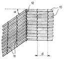
- This figure schematically represents a fragment of a network of glass strands according to the invention.
- This network consists of a series of roving strands 10 arranged parallel to each other in a plane.
- Each wick has a titer of 1200 tex and it is made up of filaments whose average diameter is of the order of 17 micrometers.
- the layer of locks 10 is held in place by a closed chain 11 made up of a polyester thread with a count of 50 dtex.
- the locks 10 are linked to each other by said chain using a loom of the knitted type with thrown stitches.
- the interval "d" between two consecutive chains is 8 millimeters.
- this network can be deformed with respect to the chain 12.
- the locks 10 have pivoted by an angle ⁇ using the loops of the chain 12 as hinges.
- This change in orientation is carried out without any crease or undulation of the web.
- the same network can be deformed in relation to several chains to follow complex shapes. Thanks to this great flexibility, the network according to the invention can play the same role as several plies juxtaposed and oriented differently, but without having any discontinuity from one end of the ply of glass strands to the other.
- a flat plate, curved at its two ends, 70 cm long and 10 cm wide was produced by stacking 10 layers of a network of strands of glass strands as defined above.
- Each layer is formed by a network of strands of threads onto which a powdered thermoplastic binder has previously been deposited.
- This binder deposited at a rate of 1% by weight of glass is a polyester sold under the reference NEOXIL 940 HF-2B by the company DSM.
- the deformation of the network is consolidated by cooling, after a heat treatment at 80 ° C.
- the stack produced was impregnated with a resin constituted by a system marketed by THE DOW CHEMICAL Co under the trademarks D.E.H. 39 and D.E.R. 332.
Landscapes
- Engineering & Computer Science (AREA)
- Textile Engineering (AREA)
- Chemical & Material Sciences (AREA)
- Chemical Kinetics & Catalysis (AREA)
- General Chemical & Material Sciences (AREA)
- Mechanical Engineering (AREA)
- Inorganic Chemistry (AREA)
- Reinforced Plastic Materials (AREA)
- Laminated Bodies (AREA)
- Nonwoven Fabrics (AREA)
- Woven Fabrics (AREA)
Abstract
Description
- La présente invention concerne un réseau de fils de verre parallèles destiné à servir de renfort d'un mélange organique.
- Les fils de verre peuvent être utilisés de multiples manières pour renforcer des matières organiques thermodurcissables ou thermoplastiques. Lorsqu'une pièce composite, obtenue à partir de telles matières renforcées est sollicitée mécaniquement lors de son emploi, il est connu de réaliser ladite pièce à partir de fils de verre orientés selon une direction privilégiée. Souvent ce type de pièce est réalisé en imprégnant de matière organique plusieurs couches de fils de verre se présentant sous la forme de nappes unidirectionnelles.
- La réalisation d'une pièce composite complexe à partir d'un tel renfort se heurte à plusieurs difficultés.
- La première réside dans le fait que les fils constituant ces nappes peuvent se déformer, se déplacer les uns par rapport aux autres, au cours des manipulations qui interviennent entre le moment de la fabrication desdites nappes et celui de la réalisation de la pièce composite.
- Pour remédier à cet inconvénient, il est connu, d'après la demande de brevet français FR-A-2 594 858 de réaliser une nappe de fils parallèles, par exemple de fils de verre, assemblés à l'aide de fils de liage transversaux thermofusibles. On obtient une nappe dont les fils ne peuvent plus se déplacer les uns par rapport aux autres grâce à un traitement thermique, qui provoque la fusion des fils de liage et, par là même, le collage des fils de verre entre eux. Après ce traitement, la nappe peut être manipulée, découpée sans aucun risque de déformation. La rigidité ainsi conférée à la nappe entrave toute déformation ultérieure qu'il serait souhaitable de lui faire subir lors de la réalisation d'une pièce composite.
- La seconde difficulté réside dans la réalisation d'une pièce composite complexe, dans lequel les renforts disposés parallèlement sont orientés dans un plan selon au moins deux directions différentes pour suivre la forme de ladite pièce. En effet, une telle pièce nécessite la juxtaposition d'au moins deux nappes de renforts parallèles selon deux orientations différentes. Cette répartition des renforts se traduit par une discontinuité lorsqu'on passe d'une nappe à l'autre. Si la zone dans laquelle se trouve cette discontinuité, qu'elle soit en surface ou au sein du matériau composite, est soumise à des efforts, des surcontraintes apparaîtront dans cette zone avec comme conséquence le risque d'une dégradation rapide du matériau. D'autre part, les orientations différentes des nappes du renfort induisent également des surcontraintes sur toute la périphérie de la pièce en matériau composite.
- La présente invention a pour objet, un réseau de fils de verre parallèles tel que lesdits fils puissent être utilisés comme renforts dans une pièce composite complexe, en évitant toute discontinuité au sein de ladite pièce.
- La présente invention a pour objet, un réseau de fils parallèles susceptibles d'être déformé et qui possède une stabilité suffisante pour être manipulé sans risquer de provoquer le déplacement accidentel d'un ou plusieurs fils lors de la réalisation d'une pièce composite complexe.
- La présente invention a pour objet, un réseau de fils de verre parallèles dans lequel le mode de liaison desdits fils entre eux est tel qu'il n'affecte pratiquement pas la résistance à la fatigue d'une pièce composite dans lequel ledit réseau sert de renfort.
- La présente invention a également pour objet un matériau composite renforcé par un tel réseau de fils de verre parallèles.
- Ces buts sont atteints grâce à un réseau de fils de verre parallèles destiné à être associé à un mélange organique pour réaliser un matériau composite, ledit réseau étant formé d'une multiplicité de fils de verre continus, disposés parallèlement sous la forme d'une nappe plane, lesdits fils étant reliés les uns aux autres par des fils disposés transversalement à ladite nappe selon un mode de liage appelé chaînette, les fils de verre étant rendus partiellement solidaires au moyen d'un liant organique thermoplastique, et les fils de liage présentant un module d'élasticité inférieur à celui du fil de verre et une température de fusion ou de ramollissement supérieure à la température de fusion ou de ramollissement du liant.
- La manipulation de la nappe de verre, la déformation du réseau de fils de verre parallèles qui lui sont associés et la conservation de cette déformation sont grandement facilitées par le dépôt d'une matière organique, liquide ou sous forme de poudre à la surface de la nappe. La quantité pondérale de matière organique déposée est généralement supérieure à 0,5% par rapport au poids de la nappe et, de préférence, inférieure à 2%.
- Par commodité, cette matière organique de dépôt sera appelée dans la suite de la description «liant».
- Le liant est déposé à une température inférieure à sa température de ramollissement ou de fusion et réchauffé à la surface de la nappe jusqu'à une température supérieure à son point de ramollissement ou de fusion afin d'assurer l'adhésion du liant à la surface de la nappe. Par ramollissement, on entend le passage de la phase solide à une phase suffisamment visqueuse pour assurer l'adhésion du liant à la nappe. La température de ramollissement ou de fusion du liant choisi est généralement supérieure à environ 40°C et inférieur à environ 130°C.
- Après refroidissement et retour au-dessous de cette température de ramollissement ou de fusion du liant et de la nappe, cette dernière présente un état de consolidation tel que sa manipulation en est grandement facilitée. Par consolidation, on entend un état tel que les caractéristiques intrinsèques du réseau de fils de verre parallèles et de la nappe déformée ne soient pas altérées par des manipulations successives.
- L'une des caractéristiques avantageuses du réseau de fils de verre selon l'invention est son aptitude à pouvoir se déformer, par exemple dans un plan, de manière à infléchir, dans une zone déterminée l'orientation des fils de verre constituant la nappe. Ce changement d'orientation est effectué, pour l'ensemble des fils de la nappe, par rapport à un des fils transversaux qui lient lesdits fils. Par commodité, ces fils transversaux seront appelés dans la suite de la description fils de liage. Par ce changement d'orientation on peut ainsi obtenir l'équivalent de deux nappes liées l'une à l'autre et faisant entre elles un angle bien défini.
- La déformation géométrique du réseau de fils de verre parallèles doit se produire à une température supérieure au point de ramollissement ou de fusion du liant. Le réseau de fils de verre ainsi déformé, après retour à une température inférieure à la température de ramollissement ou de fusion du liant, présente également un état de consolidation tel que sa manipulation en est grandement facilitée et sa géométrie de déformation facilement conservée.
- L'une des caractéristiques avantageuses du réseau de fils selon l'invention est que les fils de liage utilisés sont constitués d'une matière dont la température de fusion ou de ramollissement est supérieure à la température de fusion ou de ramollissement du liant. Ainsi le réseau peut-il être déformé et consolidé par refroidissement à plusieurs reprises sans jamais perdre la potentialité d'orientation des fils passant à travers les boucles de la chaînette.
- Lors de la réalisation d'un matériau composite renforcé par un réseau de fils de verre parallèles du type de celui de l'invention, les fils de liage lorsqu'ils sont en verre, abaissent considérablement la résistance à la fatigue de ce matériau, à cause des effets d'orientation transverse par rapport à la direction principale de sollicitation mécanique du matériau.
- Un tel phénomène est nettement réduit lorsque le fil de liage est constitué d'une matière dont le module d'élasticité est inférieur à celui du verre, et cela d'autant mieux que ce module se rapproche de celui de la matrice organique à renforcer.
- Le mode de liage des fils de la nappe du réseau selon l'invention est une chaînette et, de préférence, une chaînette à mailles fermées. Ce mode de liage par une chaînette permet aux fils de la nappe de verre d'être maintenus au sein de celle-ci, tendus et sans ondulations ce qui permet d'accroître considérablement la résistance en fatigue d'un matériau composite constitué d'un tel renfort.
- D'autre part, ce mode de liage permet de conserver un espacement constant et défini entre les fils de verre de la nappe afin d'assurer un bon écoulement de la résine organique au sein du renfort durant la phase de moulage pour l'obtention du matériau composite.
- Enfin, ce mode de liage, de par sa cohésion, permet d'éviter tout risque de déplacement aléatoire des mèches de fils de verre durant la phase de moulage lorsque la pression d'injection ou de compression devient élevée, ce qui améliore la reproductibilité des pièces moulées.
- Le fil choisi comme fil de liage ou chaînette est de préférence un fil organique. Lorsque le réseau de fils selon l'invention est destiné à renforcer une matière organique déterminée, le fil de liage ou chaînette peut être constitué d'une matière identique ou similaire.
- L'aptitude à la déformation du réseau de fils de verre selon l'invention est étroitement dépendante de l'intervalle séparant deux fils de liage ou chaînettes consécutifs. Pour obtenir une inflexion de la nappe de fils parallèle dans un plan, sans provoquer de plis ou d'ondulations, il est préférable que l'intervalle le plus faible entre deux fils de liage consécutifs soit au moins égal à 5 millimètres. Les fils de liage dans le réseau de fils selon l'invention sont en général régulièrement espacés.
- Dans le réseau de fils, les fils de verre peuvent être répartis dans la nappe sous la forme d'une série de mèches, chaque mèche étant formée par la réunion de plusieurs fils. Dans le cadre de l'invention, les mèches formant la nappe ont un titre d'au moins 300 tex. Les fils de verre, répartis ou non sous forme de mèches, sont eux-mêmes constitués d'une multiplicité de filaments continus dont le diamètre moyen est au moins égal à 10 micromètres.
- Le réseau de fils selon l'invention est utilisé pour renforcer des matières organiques thermodurcissables ou thermoplastiques. Le matériau composite réalisé comprend au moins une couche d'un tel réseau. Dans ce matériau la ou les couches de fils qui le renforcent peuvent être constituées chacune d'un réseau selon l'invention dont la nappe est déformée par rapport à au moins un fil de liage, de manière que les fils sont répartis en au moins deux groupes de fils parallèles faisant entre eux un angle déterminé. Ainsi, le matériau composite peut comprendre une ou plusieurs nappes de fils parallèles qui, après une ou plusieurs déformations, sont restées planes. Chaque déformation a alors simplement consisté en une rotation dans le plan initial de chaque fil ou mèche autour des différents points de chaînette d'un fil de liage déterminé.
- Le matériau composite peut également comprendre une ou plusieurs nappes qui, après une ou plusieurs déformations, présentent une courbure, un cintrage par rapport au plan initial de la nappe. Chaque déformation a alors consisté en une rotation de chaque fil ou mèche autour d'au moins un fil de liage, choisi comme axe de déformation, de manière à former un angle déterminé par rapport au plan initial de la nappe. Le réseau de fils parallèles selon l'invention permet ainsi de réaliser des pièces composites tridimensionnelles de forme complexe.
- Les avantages de la présente invention seront mieux compris à travers l'exemple décrit ci-après qui est illustré par une figure unique.
- Cette figure représente schématiquement un fragment d'un réseau de fils de verre selon l'invention.
- Ce réseau est constitué d'une série de mèches de stratifil 10 disposées parallèlement les unes aux autres dans un plan. Chaque mèche a un titre de 1200 tex et elle est constituée de filaments dont le diamètre moyen est de l'ordre de 17 micromètres. La nappe de mèches 10 est maintenue par une chaînette fermée 11 constituée d'un fil polyester d'un titre de 50 dtex. Les mèches 10 sont liées entre elles par ladite chaînette en utilisant un métier du type tricot à mailles jetées. L'intervalle « d » entre deux chaînettes consécutives est de 8 millimètres.
- Comme l'indique la figure, ce réseau peut être déformé par rapport à la chaînette 12. En restant dans un plan les mèches 10 ont pivoté d'un angle α en utilisant les boucles de la chaînette 12 comme charnières. Ce changement d'orientation est effectué sans formation de pli ou d'ondulation de la nappe. Le même réseau peut être déformé par rapport à plusieurs chaînettes pour suivre des formes complexes. Grâce à cette grande souplesse, le réseau selon l'invention peut jouer le même rôle que plusieurs nappes juxtaposées et orientées différemment, mais sans présenter de discontinuité d'une extrémité de la nappe de fils de verre à l'autre.
- Ainsi, une plaque plane, incurvée à ses deux extrémités, de 70 cm de longueur de 10 cm de largeur a été réalisée en empilant 10 couches d'un réseau de mèches de fils de verre tel que défini précédemment.
- Chaque couche est formée d'un réseau de mèches de fils sur lequel a été déposé préalablement un liant thermoplastique en poudre. Ce liant déposé à raison de 1% en poids de verre est un polyester commercialisé sous la référence NEOXIL 940 HF-2B par la Société DSM. La déformation du réseau est consolidée par le refroidissement, après un traitement thermique à 80°C.
- L'empilement réalisé a été imprégné d'une résine constituée par un système commercialisé par la Société THE DOW CHEMICAL Co sous les marques de fabrique D.E.H. 39 et D.E.R. 332.
Claims (9)
- Réseau de fils parallèles destiné à être associé à un mélange organique pour réaliser un matériau composite, ledit réseau étant formé d'une multiplicité de fils de verre continus, disposés parallèlement sous la forme d'une nappe plane, lesdits fils étant reliés les uns aux autres par des fils disposés transversalement à ladite nappe selon un mode de liage appelé chaînette, les fils de verre étant rendus partiellement solidaires au moyen d'un liant organique thermoplastique, et les fils de liage présentant un module d'élasticité inférieur à celui du fils de verre et une température de fusion ou de ramollisement supérieure à la température de fusion ou de ramollissement du liant.
- Réseau selon la revendication 1, caractérisé en ce que la température de fusion du liant est comprise entre environ 40 et 130°C.
- Réseau selon la revendication 1 ou 2, caractérisé en ce que les fils de liage sont régulièrement espacés selon un intervalle d'au moins 5 millimètres environ.
- Réseau selon l'une quelconque des revendications précédentes, caractérisé en ce que les fils de verre sont répartis dans la nappe sous la forme d'une série de mèches, chaque mèche ayant un titre au moins égal à 300 Tex.
- Réseau selon l'une quelconque des revendications précédentes, caractérisé en ce que les filaments de verre sont constitués de filaments dont le diamètre moyen est au moins égal à 10 micromètres.
- Matériau composite formé d'un mélange organique thermodurcissable ou thermoplastique renforcé par des fils de verre, caractérisé en ce qu'il comprend au moins une couche d'un réseau de fils de verre tel que défini par l'une quelconque des revendications 1 à 5.
- Matériau composite selon la revendication 6, caractérisé en ce que la ou les couches de fils qui renforcent ledit matériau sont constituées chacune d'un réseau dont la nappe de fils de verre est déformée par rapport à au moins un fil de liage, de manière que les fils sont répartis en au moins deux groupes de fils parallèles faisant entre eux un angle déterminé.
- Matériau composite selon la revendication 7, caractérisé en ce que la nappe est déformée en demeurant dans un plan, chaque fil ou mèche formant ladite nappe ayant subi une rotation autour de chaque axe perpendiculaire à ladite nappe et passant dans la zone de contact entre ledit fil ou ladite mèche et le fil de liage choisi comme axe de déformation.
- Matériau composite selon l'une des revendications 6 à 8, caractérisé en ce qu'il comprend au moins deux couches d'un réseau formé d'une nappe de fils de verre rendus solidaires par une chaînette polyester, lesdites couches renforçant un mélange à base de résine époxyde.
Applications Claiming Priority (2)
| Application Number | Priority Date | Filing Date | Title |
|---|---|---|---|
| FR9315604A FR2714398B1 (fr) | 1993-12-24 | 1993-12-24 | Réseau de fils de verre et matériau composite renforcé par ledit réseau. |
| FR9315604 | 1993-12-24 |
Publications (2)
| Publication Number | Publication Date |
|---|---|
| EP0659923A1 true EP0659923A1 (fr) | 1995-06-28 |
| EP0659923B1 EP0659923B1 (fr) | 1998-06-10 |
Family
ID=9454361
Family Applications (1)
| Application Number | Title | Priority Date | Filing Date |
|---|---|---|---|
| EP19940403005 Expired - Lifetime EP0659923B1 (fr) | 1993-12-24 | 1994-12-23 | Réseau de fils de verre et matériau composite renforcé par ledit réseau |
Country Status (6)
| Country | Link |
|---|---|
| US (1) | US5520984A (fr) |
| EP (1) | EP0659923B1 (fr) |
| JP (1) | JPH07216686A (fr) |
| DE (1) | DE69410967T2 (fr) |
| ES (1) | ES2119117T3 (fr) |
| FR (1) | FR2714398B1 (fr) |
Cited By (1)
| Publication number | Priority date | Publication date | Assignee | Title |
|---|---|---|---|---|
| CN103966721A (zh) * | 2013-01-24 | 2014-08-06 | 曾凯熙 | 复合材料编织布及其编织方法 |
Families Citing this family (8)
| Publication number | Priority date | Publication date | Assignee | Title |
|---|---|---|---|---|
| FR2796969B1 (fr) * | 1999-07-28 | 2001-08-31 | Mermet Sa | Renfort textile complexe |
| DE10156875B4 (de) * | 2001-11-14 | 2007-05-31 | Institut Für Verbundwerkstoffe Gmbh | Dreidimensionale Verstärkungsstrukur für Faser-Kunststoff-Verbundwerkstoffe und Verfahren zu deren Herstellung aus einer ebenen Struktur |
| FR2839320B1 (fr) * | 2002-05-02 | 2004-09-17 | Saint Gobain Vetrotex | Bobine de fil en fibres de verre |
| WO2016036663A1 (fr) * | 2014-09-02 | 2016-03-10 | The University Of South Alabama | Nanocomposite poreux et procédé apparenté |
| MA43857A (fr) * | 2016-01-11 | 2018-11-21 | Lm Wp Patent Holding As | Élément d'intégration pour une pale de turbine éolienne |
| DE102017127868A1 (de) * | 2017-11-24 | 2019-05-29 | Saertex Gmbh & Co. Kg | Unidirektionales Gelege und dessen Verwendung |
| CN108049020A (zh) * | 2018-01-05 | 2018-05-18 | 宜宾海丝特纤维有限责任公司 | 一种缠绕机构 |
| JP7274159B1 (ja) * | 2022-09-21 | 2023-05-16 | ユニチカ株式会社 | ガラスクロス及びガラスクロスの製造方法 |
Citations (7)
| Publication number | Priority date | Publication date | Assignee | Title |
|---|---|---|---|---|
| FR1469065A (fr) * | 1965-12-13 | 1967-02-10 | Chomarat & Cie | Procédé de fabrication d'armatures en fibres de verre |
| FR2278818A1 (fr) * | 1974-07-15 | 1976-02-13 | Chomarat & Cie | Revetement textile de parois et procede pour le fabriquer |
| FR2416715A1 (fr) * | 1978-02-14 | 1979-09-07 | Huyck Corp | Structure de filtre aux dimensions stables |
| JPS55117649A (en) * | 1979-03-05 | 1980-09-10 | Toyota Motor Co Ltd | Composite material with high strength |
| FR2558180A1 (fr) * | 1984-01-12 | 1985-07-19 | Glasseide Oschatz K | Procede de fabrication de materiaux de support |
| EP0198776A1 (fr) * | 1985-04-04 | 1986-10-22 | ETABLISSEMENTS LES FILS D'AUGUSTE CHOMARAT & CIE. Société Anonyme | Armature textile utilisable pour la réalisation de complexes stratifiés et nouveau type de stratifiés comportant une telle armature |
| FR2594858A1 (fr) * | 1986-02-27 | 1987-08-28 | Chomarat & Cie | Armature textile utilisable pour la realisation de complexes stratifies |
Family Cites Families (2)
| Publication number | Priority date | Publication date | Assignee | Title |
|---|---|---|---|---|
| US3819461A (en) * | 1969-08-19 | 1974-06-25 | Stevens & Co Inc J P | Unidirectional, high modulus knitted fabrics |
| US4988469A (en) * | 1988-11-21 | 1991-01-29 | United Technologies Corporation | Method of fabricating fiber reinforced composite articles by resin transfer molding |
-
1993
- 1993-12-24 FR FR9315604A patent/FR2714398B1/fr not_active Expired - Fee Related
-
1994
- 1994-12-22 US US08/361,499 patent/US5520984A/en not_active Expired - Fee Related
- 1994-12-23 DE DE69410967T patent/DE69410967T2/de not_active Expired - Fee Related
- 1994-12-23 ES ES94403005T patent/ES2119117T3/es not_active Expired - Lifetime
- 1994-12-23 EP EP19940403005 patent/EP0659923B1/fr not_active Expired - Lifetime
- 1994-12-26 JP JP32275094A patent/JPH07216686A/ja active Pending
Patent Citations (7)
| Publication number | Priority date | Publication date | Assignee | Title |
|---|---|---|---|---|
| FR1469065A (fr) * | 1965-12-13 | 1967-02-10 | Chomarat & Cie | Procédé de fabrication d'armatures en fibres de verre |
| FR2278818A1 (fr) * | 1974-07-15 | 1976-02-13 | Chomarat & Cie | Revetement textile de parois et procede pour le fabriquer |
| FR2416715A1 (fr) * | 1978-02-14 | 1979-09-07 | Huyck Corp | Structure de filtre aux dimensions stables |
| JPS55117649A (en) * | 1979-03-05 | 1980-09-10 | Toyota Motor Co Ltd | Composite material with high strength |
| FR2558180A1 (fr) * | 1984-01-12 | 1985-07-19 | Glasseide Oschatz K | Procede de fabrication de materiaux de support |
| EP0198776A1 (fr) * | 1985-04-04 | 1986-10-22 | ETABLISSEMENTS LES FILS D'AUGUSTE CHOMARAT & CIE. Société Anonyme | Armature textile utilisable pour la réalisation de complexes stratifiés et nouveau type de stratifiés comportant une telle armature |
| FR2594858A1 (fr) * | 1986-02-27 | 1987-08-28 | Chomarat & Cie | Armature textile utilisable pour la realisation de complexes stratifies |
Non-Patent Citations (1)
| Title |
|---|
| DATABASE WPI Section Ch Week 8043, Derwent World Patents Index; Class A32, AN 80-75991 * |
Cited By (1)
| Publication number | Priority date | Publication date | Assignee | Title |
|---|---|---|---|---|
| CN103966721A (zh) * | 2013-01-24 | 2014-08-06 | 曾凯熙 | 复合材料编织布及其编织方法 |
Also Published As
| Publication number | Publication date |
|---|---|
| US5520984A (en) | 1996-05-28 |
| FR2714398B1 (fr) | 1996-03-08 |
| EP0659923B1 (fr) | 1998-06-10 |
| DE69410967D1 (de) | 1998-07-16 |
| JPH07216686A (ja) | 1995-08-15 |
| DE69410967T2 (de) | 1999-03-11 |
| FR2714398A1 (fr) | 1995-06-30 |
| ES2119117T3 (es) | 1998-10-01 |
Similar Documents
| Publication | Publication Date | Title |
|---|---|---|
| CA2683606C (fr) | Procede de fabrication d'un materiau composite dans lequel au moins un fil torsade est depose | |
| EP1373621B1 (fr) | Procede et dispositif de fabrication d'une plaque composite a renfort fibreux multiaxial | |
| EP0303534B1 (fr) | Structure textile pour la réalisation de stratifiés à hautes propriétés mécaniques | |
| EP0270411A1 (fr) | Structure textile permettant la réalisation d'articles stratifiés composites par moulage par injection | |
| EP0419645B1 (fr) | Structure textile deformable | |
| EP0398787B1 (fr) | Dispositif frangé de protection thermique de structure et procédé adapté à sa fabrication | |
| EP0659923B1 (fr) | Réseau de fils de verre et matériau composite renforcé par ledit réseau | |
| FR2739674A1 (fr) | Ruban plat notamment pour renforcer des conduites, son procede de fabrication, et conduites renforcees par de tels rubans | |
| FR2683554A1 (fr) | Tissu tri-dimensionnel pour composite. | |
| WO2005072940A1 (fr) | Complexes de renforcement comportant des fils raidisseurs | |
| FR2705370A1 (fr) | Composites, tissus et préformes à base de carbone à ultra-hautes performances, et procédé pour leur fabrication. | |
| EP2467518B1 (fr) | Renfort á mèches de fils de verre parallèles | |
| EP1466045B1 (fr) | Structure fibreuse pour la realisation de materiaux composites | |
| CA2006411A1 (fr) | Structures textiles, utiles comme renforts dans la fabrication de materiaux composites, et fils techniques pour de telles structures | |
| FR2949238A1 (fr) | Armature textile a fils de verre continus | |
| WO2001016418A1 (fr) | Procede et dispositif de fabrication de plaques composites | |
| EP1348791A1 (fr) | Complexe de renforcement | |
| EP1350615A1 (fr) | Produit de renfort | |
| EP3645256B1 (fr) | Matériau composite constitué de fibres tissées pré-imprégnées | |
| FR2848227A1 (fr) | Etoffe textile apte a etre integree dans une armature de renforcement, et machine pour la realisation de telles etoffes | |
| EP3481983B1 (fr) | Utilisation d'un renfort textile adapte pour l'emploi dans un procede d'impregnation par une resine thermoplastique | |
| FR2861749A1 (fr) | Mat deformable a renfort fibreux pour la fabrication de composites a matrice thermoplastique | |
| EP0465382A1 (fr) | Structure textile permettant de réaliser des articles stratifiés plats ou en forme |
Legal Events
| Date | Code | Title | Description |
|---|---|---|---|
| PUAI | Public reference made under article 153(3) epc to a published international application that has entered the european phase |
Free format text: ORIGINAL CODE: 0009012 |
|
| AK | Designated contracting states |
Kind code of ref document: A1 Designated state(s): BE DE ES FR GB IT |
|
| 17P | Request for examination filed |
Effective date: 19951208 |
|
| GRAG | Despatch of communication of intention to grant |
Free format text: ORIGINAL CODE: EPIDOS AGRA |
|
| 17Q | First examination report despatched |
Effective date: 19970908 |
|
| GRAG | Despatch of communication of intention to grant |
Free format text: ORIGINAL CODE: EPIDOS AGRA |
|
| GRAH | Despatch of communication of intention to grant a patent |
Free format text: ORIGINAL CODE: EPIDOS IGRA |
|
| GRAH | Despatch of communication of intention to grant a patent |
Free format text: ORIGINAL CODE: EPIDOS IGRA |
|
| GRAA | (expected) grant |
Free format text: ORIGINAL CODE: 0009210 |
|
| AK | Designated contracting states |
Kind code of ref document: B1 Designated state(s): BE DE ES FR GB IT |
|
| REF | Corresponds to: |
Ref document number: 69410967 Country of ref document: DE Date of ref document: 19980716 |
|
| ITF | It: translation for a ep patent filed | ||
| GBT | Gb: translation of ep patent filed (gb section 77(6)(a)/1977) |
Effective date: 19980827 |
|
| REG | Reference to a national code |
Ref country code: ES Ref legal event code: FG2A Ref document number: 2119117 Country of ref document: ES Kind code of ref document: T3 |
|
| PG25 | Lapsed in a contracting state [announced via postgrant information from national office to epo] |
Ref country code: GB Free format text: LAPSE BECAUSE OF NON-PAYMENT OF DUE FEES Effective date: 19981223 |
|
| PG25 | Lapsed in a contracting state [announced via postgrant information from national office to epo] |
Ref country code: BE Free format text: LAPSE BECAUSE OF NON-PAYMENT OF DUE FEES Effective date: 19981231 |
|
| PLBE | No opposition filed within time limit |
Free format text: ORIGINAL CODE: 0009261 |
|
| STAA | Information on the status of an ep patent application or granted ep patent |
Free format text: STATUS: NO OPPOSITION FILED WITHIN TIME LIMIT |
|
| 26N | No opposition filed | ||
| BERE | Be: lapsed |
Owner name: VETROTEX FRANCE Effective date: 19981231 |
|
| GBPC | Gb: european patent ceased through non-payment of renewal fee |
Effective date: 19981223 |
|
| PG25 | Lapsed in a contracting state [announced via postgrant information from national office to epo] |
Ref country code: FR Free format text: LAPSE BECAUSE OF NON-PAYMENT OF DUE FEES Effective date: 19990831 |
|
| REG | Reference to a national code |
Ref country code: FR Ref legal event code: ST |
|
| PG25 | Lapsed in a contracting state [announced via postgrant information from national office to epo] |
Ref country code: DE Free format text: LAPSE BECAUSE OF NON-PAYMENT OF DUE FEES Effective date: 19991001 |
|
| PG25 | Lapsed in a contracting state [announced via postgrant information from national office to epo] |
Ref country code: ES Free format text: LAPSE BECAUSE OF NON-PAYMENT OF DUE FEES Effective date: 19991224 |
|
| REG | Reference to a national code |
Ref country code: ES Ref legal event code: FD2A Effective date: 20000114 |
|
| PG25 | Lapsed in a contracting state [announced via postgrant information from national office to epo] |
Ref country code: IT Free format text: LAPSE BECAUSE OF NON-PAYMENT OF DUE FEES;WARNING: LAPSES OF ITALIAN PATENTS WITH EFFECTIVE DATE BEFORE 2007 MAY HAVE OCCURRED AT ANY TIME BEFORE 2007. THE CORRECT EFFECTIVE DATE MAY BE DIFFERENT FROM THE ONE RECORDED. Effective date: 20051223 |