EP0659532A2 - Moule sans carotte pour disque et procédé de moulage de disque - Google Patents
Moule sans carotte pour disque et procédé de moulage de disque Download PDFInfo
- Publication number
- EP0659532A2 EP0659532A2 EP94120515A EP94120515A EP0659532A2 EP 0659532 A2 EP0659532 A2 EP 0659532A2 EP 94120515 A EP94120515 A EP 94120515A EP 94120515 A EP94120515 A EP 94120515A EP 0659532 A2 EP0659532 A2 EP 0659532A2
- Authority
- EP
- European Patent Office
- Prior art keywords
- disc
- hot plunger
- gate
- leading end
- plunger
- Prior art date
- Legal status (The legal status is an assumption and is not a legal conclusion. Google has not performed a legal analysis and makes no representation as to the accuracy of the status listed.)
- Withdrawn
Links
- 238000000465 moulding Methods 0.000 title claims abstract description 86
- 238000000034 method Methods 0.000 title claims description 14
- 239000011347 resin Substances 0.000 claims abstract description 63
- 229920005989 resin Polymers 0.000 claims abstract description 63
- 238000001816 cooling Methods 0.000 claims abstract description 52
- 230000007246 mechanism Effects 0.000 claims abstract description 14
- 238000002347 injection Methods 0.000 claims description 32
- 239000007924 injection Substances 0.000 claims description 32
- 239000006185 dispersion Substances 0.000 claims description 13
- 238000007789 sealing Methods 0.000 claims description 5
- 230000009977 dual effect Effects 0.000 claims 1
- 239000000758 substrate Substances 0.000 description 18
- 238000001746 injection moulding Methods 0.000 description 11
- 239000012768 molten material Substances 0.000 description 6
- 230000000694 effects Effects 0.000 description 5
- 230000013011 mating Effects 0.000 description 5
- 238000004080 punching Methods 0.000 description 5
- 238000010276 construction Methods 0.000 description 4
- 238000010586 diagram Methods 0.000 description 4
- 238000010438 heat treatment Methods 0.000 description 4
- 238000004519 manufacturing process Methods 0.000 description 4
- 239000000463 material Substances 0.000 description 4
- 230000008569 process Effects 0.000 description 4
- FGUUSXIOTUKUDN-IBGZPJMESA-N C1(=CC=CC=C1)N1C2=C(NC([C@H](C1)NC=1OC(=NN=1)C1=CC=CC=C1)=O)C=CC=C2 Chemical compound C1(=CC=CC=C1)N1C2=C(NC([C@H](C1)NC=1OC(=NN=1)C1=CC=CC=C1)=O)C=CC=C2 FGUUSXIOTUKUDN-IBGZPJMESA-N 0.000 description 2
- 230000009471 action Effects 0.000 description 2
- 238000007664 blowing Methods 0.000 description 2
- 238000004891 communication Methods 0.000 description 2
- 230000001737 promoting effect Effects 0.000 description 2
- 238000007711 solidification Methods 0.000 description 2
- 230000008023 solidification Effects 0.000 description 2
- 125000006850 spacer group Chemical group 0.000 description 2
- 230000006835 compression Effects 0.000 description 1
- 238000007906 compression Methods 0.000 description 1
- 238000005520 cutting process Methods 0.000 description 1
- 230000007547 defect Effects 0.000 description 1
- 230000006866 deterioration Effects 0.000 description 1
- 239000007789 gas Substances 0.000 description 1
- 230000017525 heat dissipation Effects 0.000 description 1
- 238000002844 melting Methods 0.000 description 1
- 230000008018 melting Effects 0.000 description 1
- 230000005499 meniscus Effects 0.000 description 1
- 239000011148 porous material Substances 0.000 description 1
- 230000009467 reduction Effects 0.000 description 1
- 230000004044 response Effects 0.000 description 1
- 230000000630 rising effect Effects 0.000 description 1
- 238000000926 separation method Methods 0.000 description 1
- 238000007493 shaping process Methods 0.000 description 1
Images


Classifications
-
- B—PERFORMING OPERATIONS; TRANSPORTING
- B29—WORKING OF PLASTICS; WORKING OF SUBSTANCES IN A PLASTIC STATE IN GENERAL
- B29C—SHAPING OR JOINING OF PLASTICS; SHAPING OF MATERIAL IN A PLASTIC STATE, NOT OTHERWISE PROVIDED FOR; AFTER-TREATMENT OF THE SHAPED PRODUCTS, e.g. REPAIRING
- B29C45/00—Injection moulding, i.e. forcing the required volume of moulding material through a nozzle into a closed mould; Apparatus therefor
- B29C45/17—Component parts, details or accessories; Auxiliary operations
- B29C45/38—Cutting-off equipment for sprues or ingates
-
- B—PERFORMING OPERATIONS; TRANSPORTING
- B29—WORKING OF PLASTICS; WORKING OF SUBSTANCES IN A PLASTIC STATE IN GENERAL
- B29C—SHAPING OR JOINING OF PLASTICS; SHAPING OF MATERIAL IN A PLASTIC STATE, NOT OTHERWISE PROVIDED FOR; AFTER-TREATMENT OF THE SHAPED PRODUCTS, e.g. REPAIRING
- B29C45/00—Injection moulding, i.e. forcing the required volume of moulding material through a nozzle into a closed mould; Apparatus therefor
- B29C45/17—Component parts, details or accessories; Auxiliary operations
- B29C45/26—Moulds
- B29C45/27—Sprue channels ; Runner channels or runner nozzles
- B29C45/28—Closure devices therefor
-
- B—PERFORMING OPERATIONS; TRANSPORTING
- B29—WORKING OF PLASTICS; WORKING OF SUBSTANCES IN A PLASTIC STATE IN GENERAL
- B29C—SHAPING OR JOINING OF PLASTICS; SHAPING OF MATERIAL IN A PLASTIC STATE, NOT OTHERWISE PROVIDED FOR; AFTER-TREATMENT OF THE SHAPED PRODUCTS, e.g. REPAIRING
- B29C45/00—Injection moulding, i.e. forcing the required volume of moulding material through a nozzle into a closed mould; Apparatus therefor
- B29C45/17—Component parts, details or accessories; Auxiliary operations
- B29C45/26—Moulds
- B29C45/263—Moulds with mould wall parts provided with fine grooves or impressions, e.g. for record discs
-
- B—PERFORMING OPERATIONS; TRANSPORTING
- B29—WORKING OF PLASTICS; WORKING OF SUBSTANCES IN A PLASTIC STATE IN GENERAL
- B29C—SHAPING OR JOINING OF PLASTICS; SHAPING OF MATERIAL IN A PLASTIC STATE, NOT OTHERWISE PROVIDED FOR; AFTER-TREATMENT OF THE SHAPED PRODUCTS, e.g. REPAIRING
- B29C45/00—Injection moulding, i.e. forcing the required volume of moulding material through a nozzle into a closed mould; Apparatus therefor
- B29C45/17—Component parts, details or accessories; Auxiliary operations
- B29C45/26—Moulds
- B29C45/27—Sprue channels ; Runner channels or runner nozzles
- B29C45/2735—Sprue channels ; Runner channels or runner nozzles for non-coaxial gates, e.g. for edge gates
-
- Y—GENERAL TAGGING OF NEW TECHNOLOGICAL DEVELOPMENTS; GENERAL TAGGING OF CROSS-SECTIONAL TECHNOLOGIES SPANNING OVER SEVERAL SECTIONS OF THE IPC; TECHNICAL SUBJECTS COVERED BY FORMER USPC CROSS-REFERENCE ART COLLECTIONS [XRACs] AND DIGESTS
- Y10—TECHNICAL SUBJECTS COVERED BY FORMER USPC
- Y10S—TECHNICAL SUBJECTS COVERED BY FORMER USPC CROSS-REFERENCE ART COLLECTIONS [XRACs] AND DIGESTS
- Y10S425/00—Plastic article or earthenware shaping or treating: apparatus
- Y10S425/81—Sound record
Definitions
- the present invention relates to a sprueless disc mold and a disc molding method for injection-molding a recording medium disc substrate such as a video disc or a compact disc (as abbreviated to CD) having an opening at its center.
- a recording medium disc substrate such as a video disc or a compact disc (as abbreviated to CD) having an opening at its center.
- the disc substrate is manufactured by an injection-molding process using a disc mold. As shown in Fig. 11, this molding process is performed by charging a cavity 56, which is formed between a mirror plate 50 of a stationary molding member and a stamper 54 mounted on a mirror plate 52 of a movable molding member, with a molten resin injected from the (not-shown) nozzle of an injector through a sprue hole 58.
- the stamper 54 is used to transfer the helical or concentric pits, which are formed with surface corrugations having a width of about 0.5 microns, as recording information data to the disc.
- This stamper 54 is fixed by having its inner circumferential edge and outer circumferential edge held on the mirror plate 52 of the movable molding member by the flanged portion 60a of a stamper holder 60.
- the disc substrate After the molten resin charged in the mold has been solidified to a predetermined hardness, the disc substrate has its center opening 66 (as shown in Fig. 12) punched out by a center punch 64 which is enabled to slide therein by using a sleeve 62 as a guide member.
- the disc substrate 1 has its shape schematically shown in a top plan view and in a section in Figs. 12 and 13.
- This disc is formed with at its center with the opening 55 and around this opening 66 with an annular groove 68 to be formed as a recess by the flanged portion of the stamper holder, and is divided across the annular groove 68 into a clamp area 70 at the inner side and a signal area 72 at the outer side. To this signal area 72, there are transferred by the stamper 54 the pits which are formed in the helical or concentric shape.
- the disc substrate 1 is thus molded by an injection-molding apparatus and is then stacked on a stacker.
- each of these substrates is formed with an annular stack rib 80 on its back providing the recording information face.
- This stack rib 80 is formed either in a radially outward or inward offset from the annular groove 68 arranged to face it on the surface or in the same position but with a larger width than that of the annular groove 68.
- the step of punching out the center opening is included to elongate the time period for the molding cycle, and powdery chip is produced by cutting the disc internal diameter through the punching step so that it is caught by the electrified disc substrate or by the stamper in the mold.
- powdery chip is produced by cutting the disc internal diameter through the punching step so that it is caught by the electrified disc substrate or by the stamper in the mold.
- the sprueless mold is noted as the disc mold for satisfying the movement.
- the disc substrate is manufactured not only by solving the defect of the prior art but also by eliminating the sprue and the runner for the passages of the molten resin to minimize the loss of the material.
- the mold of this kind is disclosed in U.S.P. No. 4,394,117, 4,391,579, 4,340,353 or 4,405,540 or Japanese Patent Laid-Open No. 212757/1993, for example.
- the mold as disclosed in U.S.P. No. 4,394,117 (corresponding to Japanese Patent Publication No. 23972/1985) to be exemplified herein, is used to manufacture a recording disc having a center opening by using an injection-molding apparatus and is equipped with a valve assembly for controlling the flow of a molten resin to be charged in the mold cavity.
- This valve assembly is exemplified by a sprue bush 100 having a hot runner structure, as shown in Fig. 14.
- This sprue bush 100 is constructed of: a stem 106 having a heating coil 102 mounted around a resin passage 103 and a conical dispersion head 104 mounted on its lower portion; and a sleeve valve 108 fitted slidably on the stem 106.
- the sleeve valve 108 is so urged to a protruded position, i.e., a closed position by spring means 114 such as a dish spring as to bring a conical face 110 of the dispersion head 104 and an annular slope 112 on the lower edge of the sleeve valve 108 into abutment against each other, but normally prevents the molten material from flowing into a cavity 116.
- spring means 114 such as a dish spring
- the molten material When the molten material is injected under pressure through the sprue bush 100, it axially flows to the dispersion head 104 and passes through a plurality of radially extending grooves until it reaches the gate reservoir. If the pressure in the sprue bush exceeds a predetermined level, the sleeve valve 108 rises in the direction of arrow A in response to that pressure until it is automatically retracted to an open position. As a result, the gate is opened by establishing a gap between the slope 112 on the lower edge of the sleeve valve and the conical face 110 of the dispersion head, to charge the cavity with the molten material.
- the material in the vicinity of the sleeve valve is pushed back to the bore of the sprue bush by the inner slope at the leading end of the valve, the material in the cavity can be prevented from being locally disturbed, and the pressure fluctuation of the molten material in the sprue bush can also be prevented from being transmitted to the inside of the cavity by closing the sleeve valve.
- the sleeve valve 108 thus constructed has an external diameter corresponding to the internal diameter of the center opening for forming the information disc, and the disc is molded with the center opening on the basis of the contour of the valve as a result that the valve moves to the closed position before the molten material solidifies. This makes it unnecessary to punch out that opening.
- the disc opening is formed such that the molten resin is separated by the leading end portion of the sleeve valve, so that the shape of the opening portion and the finish of the surface when the resin solidifies are not always satisfactory without neither any step nor any bur. Since, moreover, the structure is made such that the resin retains its passage opening by its own flow, it is limited by the fact that the control for starting the separation of the center opening before the end of injection cannot be achieved.
- the mold of this kind is equipped, as shown in Fig. 15, with a sprue bush 122 for forming an annular gate 120 in a slightly recess plane on the disc face, as spaced from the center opening of the disc.
- This sprue bush 122 is given a hot runner structure in which a conical dispersion head 130 is fixedly arranged in abutment against the bottom of a step 128 having a heat cartridge 124 therein and a heating coil 126 arranged around its upper portion.
- a resin passage 134 is formed in a conical face 132 between the stem 128 and the dispersion head 130.
- the dispersion head 130 is formed with a plurality of spacer steps 136, which are circumferentially arranged to inject the molten resin radially outward, so that the molten resin flowing from the center hole 138 of the stem is divided into homogeneous annular flows to pass between the conical faces to the cavity. Moreover, the resin material thus annularly dispersed through those spacer steps 136 is accelerated while flowing toward the cavity so that it does not solidify with an excellent flow to the gate.
- the sprue bush 122 and the dispersion head 130 are fixed to each other so that the gate is always opened.
- the gate mark is left on the face of the molded disc. If this gate mark rises from the disc face, a post-treatment for removing it may become necessary.
- the present invention has an object to provide a sprueless disc mold and a molding method thereof, which is freed from any gate mark to be formed at the time of molding a disc and which is accurately molded with a center opening.
- Another object of the present invention is to mold the disc in high productivity without any NG molding by improving the smoothness of the disc surface and the double refractive index of the periphery of the opening.
- a sprueless disc mold comprising: a stationary molding member and a movable molding member; mirror plates arranged to face each other between the stationary molding member and the movable molding member thereby to form a cavity for molding a disc; a stamper arranged on at least one of the mirror plates for transferring recording information to the disc; a gate insert arranged in a hollow portion between a gate leading to the cavity and an inlet port of a molten resin; a hot plunger adapted to come into sliding contact with the gate insert and heated and held; drive means for moving back and forth the hot plunger to open/close the gate; an ejector mechanism for protruding the molded disc; and a cooling air passage for cooling down the leading end of the hot plunger, wherein the hot plunger includes a shoulder portion formed at its leading end portion, wherein the gate insert includes: a leading end face forming a portion of a cavity face together with the
- the present invention is further characterized by a cooling air passage for cooling down the leading end portion of the hot plunger.
- an ejector mechanism includes an ejector sleeve adapted to be fitted in the outer circumference of the central engagement portion of the hot plunger and to come into abutment against the shoulder portion when the mold is to be closed.
- the drive means includes: a first hydraulic cylinder fixed in the stationary molding member for moving back and forth a core plate coupled to the hot plunger; and a second hydraulic cylinder for driving a stopper plate into and out of one side portion of the core plate.
- the first hydraulic cylinder can be fixed by inserting the stopper plate into the core plate to fix the position of the hot plunger which might otherwise be fluctuated by the injection pressure.
- a method for molding a disc by using the sprueless disc mold according to the first aspect of the present invention comprises the steps of: retracting, after the operation of closing the mold, the hot plunger from a first hydraulic cylinder to open the gate thereby to inject and charge the cavity with the molten resin, and then applying a proper holding pressure; protruding the hot plunger, before the molten resin solidifies, to bring the outer circumference of its leading end portion into sliding contact with the inner circumference of the gate insert to close the gate; further protruding the hot plunger while compressing the molten resin with the shoulder portion of the leading end portion of the hot plunger pushing the cavity face, to bring the shoulder portion to a position in which a clamp area face matching a predetermined thickness of the disc is formed; and forming, at the end of the compressing operation of the hot plunger, the center opening of the disc around the central engagement portion at the leading end portion of the hot plunger and bringing the annular recess
- the annular recess in the leading end portion of the gate insert and the chamfered portion on the leading end portion of the hot plunger are brought into contact with each other to form the annular recess so that the shape of the stack rib of the disc can be formed to eliminate the gate mark completely.
- the cooling air is fed to the cooling air passage at the leading end portion of the hot plunger, the molten resin in the cavity is cooled down either simultaneously with the mold cooling step in the molding cycle or soon before the end of the charging operation so that its solidification can be promoted.
- the center hole of the disc is determined by the external diameter of the central engagement portion at the leading end portion of the hot plunger so that it is formed by not the punching step but by the molding step during the molding cycle.
- the hot plunger is in sliding contact with gate insert and has its leading end portion fitted at its central engagement portion in the ejector mechanism so that it can be always centered.
- the hot plunger can have its external diameter enlarged to have the heating means therein thereby to optimize the heated state of the molten resin.
- the compressing action of the hot plunger to protrude the same in the direction to decrease its capacity is carried out to compress the clamp area face of the disc and accordingly the entire molten resin in the cavity by the shoulder portion of the hot plunger.
- this gate sealing operation can act to apply the pressure load to the inside of the cavity and need not be ended during the injection step by moving the hot plunger, so that the pressure control can be made accurate at the injection step.
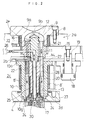
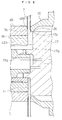
- Fig. 1 is a section showing a structure of a disc molding sprueless mold according to the present invention.
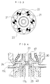
- Fig. 2 is an enlarged section showing an essential portion or a portion of the mold of the present invention.
- the mold is constructed of a stationary molding member 2 and a movable molding member 3, and a cavity 4 for molding a disc is formed between the mating faces of the two members.
- the mold has a construction for controlling the opening/closing of a gate by a drive source such as a hydraulic cylinder, as will be described later.
- the stationary molding member 2 has a stationary mold body constructed by fastening a stationary mounting plate 2a, first and second intermediate plates 2b and 2c and a stationary mirror plate 2d to one another by means of bolts to form an integral structure.
- This mold body is formed in its central portion with a hollow portion 5 which has a structure transversely extending, as shown, to arrange a hot runner structure therein.
- the movable molding member 3 is constructed of: a movable mounting plate 3a to be mounted on the movable table of an injection-molding apparatus; an intermediate plate 3b; and an ejector mechanism 6 for ejecting the molded disc.
- the intermediate plate 3b is constructed to mount a movable mirror plate 3c in its recess and to arrange on the mirror plate a stamper 7 for transferring the recording information data to the disc.
- the hot runner structure is generally constructed of: an inlet member 9 and a gate insert 10 to be heated by external heaters 8 and 8'; and a hot plunger 11 arranged in and surrounded by these members.
- the inlet member 9 is inserted into a center opening 2e of the mounting plate 2a and is formed with: a meniscus surface 9a to abut against the (not-shown) nozzle of the injection apparatus; and an internal hole 12 communicating with its inlet port 9b.
- an annular external heater 8 for holding a molten resin in the internal hole 12 in a heated state.
- the gate insert 10 is formed into a sleeve shape having a flange 10a and is arranged coaxially with the inlet member 9.
- the gate insert 10 is inserted into the center opening of the stationary mirror plate 2d and is fixed such that its flange 10a is sandwiched between the intermediate plates 2b and 2c and such that its stepped portion 10g abuts against the shoulder portion of the stationary mirror plate 2d.
- the annular external heater 8' for holding the molten resin in its internal hole 13 in the heated state, as in the inlet member 9.
- the hot plunger 11 is constructed of a cylindrical body 14, a core plate 15, a joint portion 16 and a plunger cap 17, and the cylindrical body 14 can slide in the gate insert while being guided in the two internal holes 12 and 13 of the inlet member 9 and the gate insert 10.
- the hot plunger 11 is driven by a plurality of first hydraulic cylinders to move back and forth in the vertical directions of Fig. 2 thereby to open/close a gate 24.
- the cylindrical body 14 is divided (vertically of Fig. 2) into two halves to receive the heater 22. Moreover, the cylindrical body 14 is coupled by the joint portion 16 to the core plate 15 which is arranged in the cavity of the intermediate plate 2b, and the hydraulic cylinder 18 fixed in the intermediate plate 2c is mounted on the core plate 15 through an adjust collar 19.
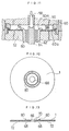
- cylindrical body 14 forms an annular chamber (or reservoir) 20 between itself and the gate insert 10 and has totally twelve holes in the outer circumferential edge of the semicircular head of the joint portion 16, as shown in Fig. 3.
- six resin passages 21 and six internal heaters 22 are alternatively arranged radially in parallel.
- the plurality of resin passages 21 are made at the leading end of the cylindrical body 14 to communicate with the annular chamber 20 so that their molten resins may merge into one resin reservoir.
- the annular chamber 20 reserves about one shot of the molten resin to flow from the gate 24 into the cavity 4 thereby to prevent deterioration of the molten resin and the weldline of the molding.
- a microheater 25 of about 170 W for holding the melting point of the resin in the chamber there is arranged around the annular chamber 20 a microheater 25 of about 170 W for holding the melting point of the resin in the chamber.
- This microheater 25 is either cast in or mounted on the outer circumference of the hot plunger 11 and is then assembled around the reservoir of the molten resin by the (not-shown) cylindrical member.
- the capacity of the annular chamber 20 may be so decided for the qualities of the moldings that the amount of the molten resin to be reserved may be more than one shot (or amount of injection).
- cylindrical body 14 is formed at its central portion with a cooling air passage 27 communicating with a port 26 from the core plate 15 such that the air passage 27 is protected by an insulating pipe 28.
- this cap 17 is equipped at its leading end with an annular ring portion 17a acting as a central engagement portion to be guided by the ejector mechanism 6 and is formed therein with a dispersion air passage 29 composed of a plurality of thin through holes communicating with the air passage 27 of the cylindrical body 14.
- the air passage 29 is given a far smaller diameter than that of the air passage 27. The air is compressed by the abrupt reduction of the effective area and is then released so that the surrounding temperature quickly drops to maximize the cooling effect.
- the leading end portion of the hot plunger 11 including the annular ring portion 17a, a shoulder portion 17b and a chamfered portion 17c can be cooled down by the cooling air passing through the cooling air passage 27, to ensure solidification of the molding and to prevent the molding from any parting deformation at the mode opening time.
- the air passage 29 is formed as a throttle for making the cooling effective.
- the throttling amount of the cooling air can be changed (in terms of the number of pores) by replacing the plunger cap 17.
- a space 30 is formed between the plunger cap 17 and the leading end of the cylindrical body 14 of the hot plunger to shield the heat coming from the microheater 25.
- the hot plunger 11 thus constructed constitutes the gate 24 at the injection time with both the leading end corner of the plunger cap 17 at its leading end portion and the inner circumference of the gate insert 10.
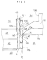
- Fig. 5 shows a sectional structure of the gate portion according to the feature of the present invention.
- the gate 24 is an annular gate because it is formed in the gap between the inner circumference (or opening edge) 10d of the gate insert and the chamfered portion (or corner portion) 17c of the shoulder portion 17b of the hot plunger cap.
- the gate insert 10 has its leading end face 10b provided for forming a cavity face, i.e., one clamp area face 70 of the disc together with the shoulder portion 17b of the hot plunger and accordingly made coextensive with the cavity surface 4a of the stationary mirror plate 2d. Moreover, the leading end face 10b is formed in its inner circumferential edge with an annular recess 10c for forming a crest face and outer slopes to form a stack rib 80 of the disc.
- the hot plunger cap 17 positioned at the leading end portion of the hot plunger 11 has its leading end corner cut to form the chamfered portion 17c thereby to form the inner slope of the stack rib 80.
- the gate is closed when the hot plunger 11 moves forward so that the outer circumference 17d of the leading end portion leading from the chamfered portion 17c of the cap comes into sliding contact with the inner circumference 10d at the leading end portion of the gate insert 10.
- the annular recess 10c is formed when the end edge of the inner circumference 10d and a bent end 47 of the chamfered portion 17c merge into each other thereby to complete the stack rib forming portion by those contouring faces, so that the gate mark after the molding process completely disappears.
- the inner circumference 10d of the gate insert forms a face to come into sliding contact with the cylindrical outer circumference 17d leading to the shoulder portion 17b of the hot plunger cap and is given a width (W) substantially equal to the difference of a hot plunger stroke (PS) from the height (H) of the stack rib.
- the inner circumference is sized to have a width (W) of about 1 mm and to have such an internal diameter as to come into sliding contact with a flat cylindrical outer circumference 17d forming the gate seal face of the hot plunger cap 17.
- the internal diameter is determined by the position of the stack rib.
- the hot plunger stroke (PS) is optimized to fall within the following relation, if the gate has a thickness (G) and if the inner circumference 10d has a width (W): PS ⁇ G + W + 0.1 (mm).
- the gate thickness (G) or the gap size between the gate insert 10 and the hot plunger cap 17 is a distance from the boundary between the inner circumference 10d and an inner slope 10e to the bent end 47 of the chamfered portion 17c of the hot plunger cap and is optimized by about 0.15 to 0.40 mm as in a CD.
- the stack rib 80 thus formed is formed into an annular ridge having a trapezoidal section of a height (H) of about 0.15 to 0.40 mm.
- this sectional shape should not be limited to a trapezoid but may be exemplified by a scalene triangle or a curved surface having a flat crest.
- Fig. 6 shows a construction of the hydraulic cylinder for controlling the opening/closing of the gate by driving the hot plunger according to the present invention.
- At least one first hydraulic cylinder 18 is arranged symmetrically at each side of the mold and is connected to the core plate 15 so that it may move the hot plunger 11 back and forth by driving the core plate 15 back and forth.
- the gate is opened by moving the hot plunger 11 back and forth simultaneously with the end of closing the mold.
- a second hydraulic cylinder 32 is provided for preventing the fluctuation of the hot plunger 11 by the injection pressure.
- This hydraulic cylinder 32 has a wedge 33 fixed at its leading end portion and has its taper face 34 formed with a recess to be dovetailed to a stopper plate 35.
- the stopper plate 35 moves in the direction of arrow B to insert its leading end projection 35a into a notch 15a of the core plate thereby to stop the motion of the hot plunger 11. In short, it is possible to prevent the fluctuation of the hot plunger 11 at the injection time.
- the hydraulic cylinders 32 can be not only mounted on the side of the mold but also assembled in the stationary table of the injection-molding apparatus, as indicated by broken lines.
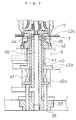
- Figs. 7 and 8 present a sectional structure and its partially enlarged section of the ejector mechanism 6 and the hot plunger cap 17 facing the former.
- the ejector mechanism 6 of the movable molding member 3 is constructed of: an air drain bush 37 buried in the central portion and formed with a center hole for allowing the cooling air to flow therethrough; an ejector sleeve 40 fitted around the air drain bush 37 and protruded through an ejector pin 38 at the mold opening time; a spring element 41, and first and second guide bushes 42 and 43.
- the ejector sleeve 40 moves forward at the mold closing end for protruding the disc substrate and backward simultaneously with the forward movement of the hot plunger.
- the molten resin before solidified flows into the occupying area of the ejector sleeve protruded into the cavity so that the amount of compressing the molten resin in the cavity 4 is accordingly reduced.
- the reaction of the resin pressure to act at the forward moving time of the hot plunger so that the compressing operation of the hot plunger can be stabilized.
- the air drain bush 37 is formed therein with a cooling air passage 39 for cooling down the leading end portion of the hot plunger 11, and the annular ring portion 17a protruding to the leading end of the hot plunger cap 17 is fitted in the space between the radially reduced leading end portion of the bush 37 and the ejector sleeve 40, so that the cooling air is prevented from leaking into the cavity by the double-sealing structure at that portion.
- the cooling air is supplied simultaneously with the end of the molding closing operation to cool down the leading end portion of the hot plunger. This supply is stopped simultaneously with the start of the mold opening operation.
- a stamper holder 45 having a stepped portion 45a, in which is fitted the inner edge 7a of the stamper 7.
- the outer edge of this stamper 7 is held by an annular stamper holder 46 (as shown in Fig. 1) which is formed on the outer circumferential end portion of the movable mirror plate 3b.
- the stamper holder 45 is centered and arranged in a prede termined position on the movable mirror plate 3b of the mold.
- the cooling air is supplied from the port 26 of the stationary molding member 2 and is discharged from a port 31 of the movable molding member 3.
- the cooling air may be supplied from the port 31 and discharged from the port 26.
- an air suction passage L for sucking the stamper 7 to the movable molding member 3 is formed to communicate with the annular groove in the movable mirror plate 3c through communication passages M and N which extend in the mating face between the movable mirror plate 3c and the stamper holder 45 and in the positions to face the stamper holder 46.
- this stamper sucking structure can be replaced by another structure equipped with an inner circumference stamper holder for holding the inner edge of the stamper.
- sucking passages there are formed: a first air suction passage P leading from a through hole 10f formed in the gate insert 10 to the mating faces of the gate insert 10 and the stationary mirror plate 2d; a second air suction passage Q leading to the side portion of the stamper holder 46; and a third air suction passage R leading to the mating faces of the stamper holder 45 an the first guide bush 42.
- the first air suction passage P is provided for releasing the disc substrate 1 from the stationary mirror plate 2d at the mold opening time
- the second and third air suction passages Q and R are associated with the operation of the ejector mechanism to suck the air so as to release the disc substrate 1 from the stamper face at the end of the mold opening operation.
- the mating faces of the stamper holder 46 and the stationary mirror plate 2d are formed with vent holes for releasing the gases in the cavity 4 when the cavity is to be charged with the molten resin by the injection pressure.
- the external heaters 8 and 8' mounted on the outer circumferences of the injection member 9 and the gate insert 10 and the internal heater 22 disposed in the hot plunger 11 are individually connected with the power supply through electric wires.
- the disc cavity 4 is formed in the gap between the stationary mirror plate 2d and the stamper 7 over the movable mirror plate 3c, as in the ordinary mold.
- the operations of the hot plunger for opening/closing the gate 24 of the cavity will be described in more detail with reference to Figs. 8 and 9.
- Fig. 8 shows the state at the injecting/charging time, in which the gate of the upper half is opened, and the state at the end of the compression operation of the hot plunger in which the gate of the lower half is closed.
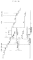
- Fig. 9 is an operation chart showing the operation states of the drive portion at the individual steps of the molding operations, in which the rightward moving positions of Fig. 1 are indicated at "+” whereas the leftward moving positions are indicated at "-".
- the hot plunger 11 is in its protruded position (as indicated at C in Fig. 10) so that both the first and second hydraulic cylinders 18 and 32 are in their retracted positions (as indicated in the leftward position "-" of Fig. 9) to close the gate 24.
- both the hydraulic cylinders are in the rightward position "+".
- the chamfered portion 17c and the recess 10c of the gate insert are positioned to form the recess of the stack rib molding space, and the shoulder portion 17b of the cap reaches to the cavity position matching the thickness of the disc.
- the ejector sleeve 40 is retracted, the molten resin flows around the annular ring portion 17a of the hot plunger cap 17 so that the center opening is formed by not the punching operation but the molding operation.
- the mold is opened by the mold operation operation. Then, the disc is pushed out by the forward and backward movements of the ejector pin so that the molded disc is extracted.
- the hot plunger 11 or the hot plunger cap 17 can move at a stroke from the position, in which the chamfered portion 17c defines a predetermined gate opening between itself and the inner circumference 10d of the gate insert, to the cavity position in which it forms the stack rib 80 together with the recess 10c of the gate insert and in which the shoulder portion 17b matches the thickness of the disc.
- the hot plunger 11 has its stroke PS set to about 1 to 2.0 mm.
- the symbol "-/+" appearing in the operation chart of Fig. 9 indicates that, in the operation of the ejector pin, the ejector pin is protruded in the course of the molding closing operation to fit the ejector sleeve in the annular ring of the hot plunger cap 17.
- the ejector sleeve guides the forward movement of the hot plunger and holds the protruded position till the injection holding after the injecting/charging operations, to raise an effect to reduce the amount of the molten resin to be compressed by the hot plunger.
- Another symbol "-/+” is used for promoting the molding cycle by operating a cooling air blow delaying timer from the start of the injecting/charging operations so that during the charging operation of the time-up, the cooling air may be fed through the cooling air passage 27 to the cooling air passage 29 of the cap 17 and discharged from the air drain bush 37 to cool down the molten resin in the cavity at an early stage.
- This cooling air is fed to the cooling step of the molding cycle, too.
- a disc is molded by using the sprueless disc mold of the present invention, as follows: first of all, the mold is closed while the ejector sleeve 40 being held in its protruded state, and after this mold closing operation, the hot plunger 11 is retracted by the drive means (i.e., the first hydraulic cylinders 18) to open the gate 24 while holding the abutting state with the leading end of the ejector sleeve 40, so that the cavity is charged with the molten resin under a predetermined injection pressure; next, after these injecting/charging operations, a proper holding pressure is applied to protrude the hot plunger 11 before the molten resin is solidified, and the outer circumference 17d of the leading end portion of the hot plunger is brought into sliding contact with the inner circumference 10d of the gate insert to close the gate 24; moreover, the shoulder portion 17b positioned at the leading end portion of the hot plunger 11 pushes the cavity face to protrude the hot plunger 11 while compressing the
- Fig. 10 illustrates the time chart for a series of operations of one injection cycle from the mold closing operation to the mold opening operation.
- a broken line A indicates the operation procedure of the injection-molding apparatus, as includes: a mold closing step (having a fast mold closing step a1 and a slow mold closing step a2); a boosting step b; an injection step (having an injection delaying step c1, an injecting/charging step c2 and an injection holding step c3); a hot plunger compressing step d; a cooling step e; a pressure releasing step f; a mold opening step (having a slow mold opening step g1, a fast mold opening step g2 and a slow mold opening step g3); an ejector protruding step h; and an ejector retracting step i.
- the mold clamping operation is started.
- a series of the molding closing step a is performed, in which the mold clamping cylinder of the injection-molding apparatus is driven to move the movable molding member at the fast mold closing step a1, and in which a limit switch LS1 is actuated to effect the slow mold closing step a2 when the movable molding member comes close to the stationary molding member, until the mold closing operation is ended at the time when the molding members come into contact with each other.
- a limit switch LS2 is actuated to execute the boosting step b so as to raise the pressure in the mold clamping cylinder to a predetermined level.
- a boosting ending pressure switch PS1 is actuated to operate the injection delaying timer (at the step c1).
- the molten resin in the heating cylinder is injected (at the step c2) into the cavity.
- the supply of the cooling air through the cooling holes 29 of the hot plunger cap 17 is started. Incidentally, this cooling air supply is completed till the end of the molding cooling step.
- the injection holding is switched to apply a proper holding pressure (i.e., the secondary injection pressure) to the molten resin in the cavity.
- a proper holding pressure i.e., the secondary injection pressure
- a timing protrusion delaying timer is operated for protruding the hot plunger to execute a hot plunger protrusion delay r2. Since, at this time, the hot plunger 11 has to be protruded before the molten resin is solidified, the protrusion delay r2 may be set to zero. This timing is determined by the operator by observing the quality of the product which is actually molded.
- the mold is cooled at the step e at the end of the injection step.
- a resin supply start delaying step m1 a charge step m2 and a suck-pack step m3 are sequentially performed at the charging operation step, as indicated by broken lines D.
- a delay timer for timing the air blow at the stationary side is operated (at a step o1), and a stationary side air blowing step o2 is started after the time-up. This prevents the solidified disc from being caught by the stationary mirror plate 2d and left at the stationary molding member at the mold opening time.
- a time period (of 0.2 secs) for the pressure releasing step f is prepared, and the mold opening operation is started to effect the slow mold opening step g1.
- Limit switches LS3 and LS4 are sequentially actuated to effect the fast mold opening step g2 and the slow mold opening step g3.
- This mold opening operation is ended by actuating a limit switch LS5 and is followed by the ejector protruding step h.
- the movable side air blow delaying timer is already timed up so that the movable side air is blown (at steps p1 and p2) simultaneously with the slow molding opening step g3.
- the disc fixed on the stamper can be released from the movable side molding member by protruding the ejector sleeve of the mold and by the air from the communication holes.
- the solenoid valve is actuated by the pressure switch PS1 to be operated after the end of the mold boosting step, so that the hot plunger is forcibly retracted (at a step r1) because it is connected to the hydraulic cylinder 18 through the core plate 15.
- the open edge of the gate insert and the chamfered portion 17c of the hot plunger are spaced from each other to form the gate port of the molten resin.
- the protrusion delaying time of the hot plunger is operated (or set to zero), and the hot plunger is protruded at a proper timing to have its cylindrical outer circumference 17d fitted on the opening edge 10d of the gate insert thereby to seal the gate 24.
- the clamp area face 70 matching the stack rib 80 and the disc thickness is then simultaneously formed.
- the disc has its center opening defined by the external size of the annular ring portion 17a of the hot plunger 11 so that it can be highly accurately formed.
- the present invention has been described in connection with its embodiment, its components can be modified within the scope of the appended claims.
- the present invention can be constructed such that the leading end portion of the hot plunger cap is formed into an annular ring shape and is fitted in the space between the ejector sleeve and the air drain bush. This construction may be reversed in the fitting joint between those recessed and bulging portions.
- the ejector sleeve is given the functions of the double sealing part of the cooling air and the guide part for moving the hot plunger forward and is held in the position till the injection holding after the injecting/charging operations thereby to reduce the amount of the molten resin to be compressed by the hot plunger, but the ejector sleeve may be given a single function to protrude.
- the leading end portion of the hot plunger to be fitted in the ejector sleeve may be given a diameter for forming the center opening of the disc.
- the disc mold of the present invention is formed with the annular recess for shaping the stack rib of a disc by bring the annular recess, which is formed in the inner circumferential edge of the leading end of the gate insert, and the chamfered portion, which is formed on the corner of the leading end portion of the hot plunger, into contact with each other in the protruded position of the hot plunger after the gate sealing.
- the gap is substantially zero in those contacting portions so that the gate is substantially made to disappear thereby to leave no gate mark in the disc.
- the molding cycle can be improved without any catch of chip or the like to enhance the production yield.
- the hot plunger can have its diameter enlarged to stabilize the molten state of the resin and to ensure the compressing actions of the hot plunger, the molten resin in the cavity can be homogeneously compressed to improve the size stability and the double refractive index of the product.
- the cooling air passage is formed in the leading end portion of the hot plunger so that the molten resin in the cavity can be cooled down separately of the mold cooling step.
Landscapes
- Engineering & Computer Science (AREA)
- Manufacturing & Machinery (AREA)
- Mechanical Engineering (AREA)
- Moulds For Moulding Plastics Or The Like (AREA)
Applications Claiming Priority (4)
| Application Number | Priority Date | Filing Date | Title |
|---|---|---|---|
| JP34815993A JP2973158B2 (ja) | 1993-12-24 | 1993-12-24 | スプルーレスディスク金型 |
| JP348159/93 | 1993-12-24 | ||
| JP30426394A JP2873786B2 (ja) | 1994-11-14 | 1994-11-14 | スプルーレスディスク金型およびそのディスク成形方法 |
| JP304263/94 | 1994-11-14 |
Publications (2)
| Publication Number | Publication Date |
|---|---|
| EP0659532A2 true EP0659532A2 (fr) | 1995-06-28 |
| EP0659532A3 EP0659532A3 (fr) | 1996-01-24 |
Family
ID=26563841
Family Applications (1)
| Application Number | Title | Priority Date | Filing Date |
|---|---|---|---|
| EP94120515A Withdrawn EP0659532A3 (fr) | 1993-12-24 | 1994-12-23 | Moule sans carotte pour disque et procédé de moulage de disque. |
Country Status (5)
| Country | Link |
|---|---|
| US (1) | US5460763A (fr) |
| EP (1) | EP0659532A3 (fr) |
| KR (1) | KR100189857B1 (fr) |
| CN (1) | CN1113465A (fr) |
| TW (1) | TW260787B (fr) |
Cited By (2)
| Publication number | Priority date | Publication date | Assignee | Title |
|---|---|---|---|---|
| WO2005095082A1 (fr) | 2004-03-31 | 2005-10-13 | Sumitomo Heavy Industries, Ltd. | Poinçon de moulage de disque, plaque à surface miroir et objet moulé |
| CN107791449A (zh) * | 2016-08-23 | 2018-03-13 | 深圳市裕展精密科技有限公司 | 注塑模具 |
Families Citing this family (26)
| Publication number | Priority date | Publication date | Assignee | Title |
|---|---|---|---|---|
| US6645417B1 (en) * | 1991-08-26 | 2003-11-11 | Dale Grove | Gateless molding |
| US5997276A (en) * | 1995-02-14 | 1999-12-07 | Sanyo Electric Co., Ltd. | Optical disc manufacturing apparatus |
| JP3294971B2 (ja) * | 1995-08-07 | 2002-06-24 | 株式会社名機製作所 | ディスク基板およびその成形用型 |
| EP0800906B1 (fr) * | 1995-10-31 | 2002-05-29 | Takaoka Seiko Co., Ltd. | Appareil de moulage par injection de type a porte avec clapet |
| JPH09180251A (ja) * | 1995-12-22 | 1997-07-11 | Pioneer Electron Corp | ディスク基板、その成形用金型及び光ディスク |
| US5783234A (en) * | 1996-07-25 | 1998-07-21 | Husky Injection Molding Systems Ltd. | Hot runner valve gate for eliminating unidirectional molecular orientation and weld lines from solidified resin used for forming molded articles |
| DE19645860A1 (de) * | 1996-11-07 | 1998-05-14 | Optimel Schmelzgustechnik Gmbh | Vorrichtung zum Verriegeln und Öffnen eines Spritzgußwerkzeuges |
| JP3224347B2 (ja) * | 1996-11-28 | 2001-10-29 | 株式会社名機製作所 | ディスク基板成形用型 |
| US6154441A (en) * | 1997-04-17 | 2000-11-28 | Imation Corp. | Method for centering a hub in an optical disc, and an optical storage system using such disc |
| US5939162A (en) * | 1997-06-12 | 1999-08-17 | Kabushiki Kaisha Meiki Seisakusho | Bonded composite disk of single-side recorded type, and method and apparatus for producing the same with high thickness accuracy |
| US5840231A (en) * | 1997-08-14 | 1998-11-24 | Husky Injection Molding Systems Ltd. | Valve gate assembly |
| US6074593A (en) * | 1998-03-13 | 2000-06-13 | Osuna-Diaz; Jesus`M. | Core pin arrangement and method for injection molding |
| JP3371224B2 (ja) * | 1998-03-19 | 2003-01-27 | 株式会社名機製作所 | ディスク成形用金型のエアーブロー方法及びその金型 |
| US6139307A (en) * | 1998-07-23 | 2000-10-31 | Imation Corp. | Assembly for molding optical data storage disks formatted on both sides |
| US6202870B1 (en) | 1999-03-29 | 2001-03-20 | Woodrow W. Pearce | Venting cap |
| EP1192034B1 (fr) * | 1999-06-07 | 2003-06-18 | Imation Corp. | Procede de moulage de disques optiques avec une l'epaississement du bord reduit |
| US6678238B1 (en) * | 1999-12-29 | 2004-01-13 | Imation Corp. | Mold for manufacturing double-sided disk shaped articles for storing data |
| CA2317779A1 (fr) * | 2000-09-06 | 2002-03-06 | Mold-Masters Limited | Corps de vanne pour le moulage par injection |
| US6611365B2 (en) * | 2001-03-20 | 2003-08-26 | Imation Corp. | Thermoplastic substrates for holographic data storage media |
| US6821460B2 (en) | 2001-07-16 | 2004-11-23 | Imation Corp. | Two-sided replication of data storage media |
| US6961950B2 (en) * | 2001-09-04 | 2005-11-01 | Imation Corp. | Variable thickness stamper for creation of flat molded substrates |
| JP2005254480A (ja) * | 2004-03-09 | 2005-09-22 | Nippon Densan Corp | バルブゲート式射出成形装置及び方法 |
| US7455889B2 (en) * | 2004-03-24 | 2008-11-25 | Imation Corp. | Holographic media fabrication techniques |
| TWI292549B (en) | 2005-06-17 | 2008-01-11 | Lite On Technology Corp | Image capturing device |
| DE102006049073A1 (de) * | 2006-10-13 | 2008-04-17 | Hasco Hasenclever Gmbh + Co Kg | Einspritzdüse zur Führung von Schmelzemasse in einer Kunststoffspritzgießform |
| CN103302773B (zh) * | 2013-06-27 | 2015-12-02 | 广州盈光科技股份有限公司 | 一种光盘模具结构 |
Citations (3)
| Publication number | Priority date | Publication date | Assignee | Title |
|---|---|---|---|---|
| EP0051252A2 (fr) * | 1980-10-31 | 1982-05-12 | Discovision Associates | Assemblage de clapet pour canal de coulée chaud d'une machine à mouler par injection |
| EP0075043A2 (fr) * | 1981-09-23 | 1983-03-30 | Discovision Associates | Assemblage de valve de canal de coulée chaud pour une machine à mouler par injection |
| JPH05212757A (ja) * | 1992-02-04 | 1993-08-24 | Meiki Co Ltd | スプルーレスディスク金型 |
Family Cites Families (8)
| Publication number | Priority date | Publication date | Assignee | Title |
|---|---|---|---|---|
| DE3167483D1 (en) * | 1980-09-05 | 1985-01-10 | Matsushita Electric Ind Co Ltd | A method of producing an information recording disk |
| US4405540A (en) * | 1980-10-31 | 1983-09-20 | Discovision Associates | Hot sprue valve assembly for an injection molding machine |
| US4439132A (en) * | 1981-06-10 | 1984-03-27 | Discovision Associates | Hot sprue assembly for an injection molding machine |
| US4412805A (en) * | 1981-06-10 | 1983-11-01 | Discovision Associates | Hot sprue assembly for an injection molding machine |
| US4394117A (en) * | 1981-06-10 | 1983-07-19 | Discovision Associates | Hot sprue sleeve valve assembly for an injection molding machine |
| JPS6023972A (ja) * | 1983-07-19 | 1985-02-06 | Toshiba Corp | 非水溶媒電池用正極 |
| JPS6023971A (ja) * | 1983-07-19 | 1985-02-06 | Toshiba Corp | 非水溶媒電池用電解液の製造方法 |
| JPH085304B2 (ja) * | 1986-07-04 | 1996-01-24 | 株式会社タイセー | 自動車用送風機の速度制御用抵抗器 |
-
1994
- 1994-12-20 US US08/360,057 patent/US5460763A/en not_active Expired - Fee Related
- 1994-12-22 TW TW083112041A patent/TW260787B/zh active
- 1994-12-23 KR KR1019940036277A patent/KR100189857B1/ko not_active IP Right Cessation
- 1994-12-23 CN CN94119233A patent/CN1113465A/zh active Pending
- 1994-12-23 EP EP94120515A patent/EP0659532A3/fr not_active Withdrawn
Patent Citations (3)
| Publication number | Priority date | Publication date | Assignee | Title |
|---|---|---|---|---|
| EP0051252A2 (fr) * | 1980-10-31 | 1982-05-12 | Discovision Associates | Assemblage de clapet pour canal de coulée chaud d'une machine à mouler par injection |
| EP0075043A2 (fr) * | 1981-09-23 | 1983-03-30 | Discovision Associates | Assemblage de valve de canal de coulée chaud pour une machine à mouler par injection |
| JPH05212757A (ja) * | 1992-02-04 | 1993-08-24 | Meiki Co Ltd | スプルーレスディスク金型 |
Non-Patent Citations (1)
| Title |
|---|
| PATENT ABSTRACTS OF JAPAN vol. 17 no. 651 (M-1519) ,3 December 1993 & JP-A-05 212757 (MEIKI CO LTD) 24 August 1993, * |
Cited By (5)
| Publication number | Priority date | Publication date | Assignee | Title |
|---|---|---|---|---|
| WO2005095082A1 (fr) | 2004-03-31 | 2005-10-13 | Sumitomo Heavy Industries, Ltd. | Poinçon de moulage de disque, plaque à surface miroir et objet moulé |
| EP1731287A1 (fr) * | 2004-03-31 | 2006-12-13 | Sumitomo Heavy Industries, Ltd. | Poinçon de moulage de disque, plaque à surface miroir et objet moulé |
| EP1731287A4 (fr) * | 2004-03-31 | 2009-11-11 | Sumitomo Heavy Industries | Poinçon de moulage de disque, plaque à surface miroir et objet moulé |
| CN107791449A (zh) * | 2016-08-23 | 2018-03-13 | 深圳市裕展精密科技有限公司 | 注塑模具 |
| CN107791449B (zh) * | 2016-08-23 | 2019-09-17 | 深圳市裕展精密科技有限公司 | 注塑模具 |
Also Published As
| Publication number | Publication date |
|---|---|
| CN1113465A (zh) | 1995-12-20 |
| TW260787B (fr) | 1995-10-21 |
| KR950017172A (ko) | 1995-07-20 |
| US5460763A (en) | 1995-10-24 |
| EP0659532A3 (fr) | 1996-01-24 |
| KR100189857B1 (ko) | 1999-06-01 |
Similar Documents
| Publication | Publication Date | Title |
|---|---|---|
| US5460763A (en) | Sprueless disc mold and disc molding method thereof | |
| EP0051253B1 (fr) | Assemblage de clapet pour canal de coulée chaud d'une machine à mouler par injection | |
| US4340353A (en) | Hot sprue valve assembly for an injection molding machine | |
| EP0361305B1 (fr) | Appareil de moulage par injection pour la fabrication de substrat de disque optique | |
| EP0355589B1 (fr) | Moule pour le moulage de la base d'un disque optique | |
| US4391579A (en) | Hot sprue valve assembly for an injection molding machine | |
| JPH06270208A (ja) | 基盤射出成形金型 | |
| US20070031533A1 (en) | Injection molding method and injection mold | |
| JPH1142685A (ja) | 成形用金型の離型機構および成形方法 | |
| EP1080862B1 (fr) | Appareil pour couper la carotte et procédé de moulage pour des disques | |
| JP2873786B2 (ja) | スプルーレスディスク金型およびそのディスク成形方法 | |
| US4405540A (en) | Hot sprue valve assembly for an injection molding machine | |
| WO1998019846A9 (fr) | Appareil et procede de moulage par injection | |
| WO1998019846A1 (fr) | Appareil et procede de moulage par injection | |
| JP2973158B2 (ja) | スプルーレスディスク金型 | |
| JP3898015B2 (ja) | 導光板の成形装置 | |
| JP4136023B2 (ja) | 光ディスク成形装置 | |
| JP2545155Y2 (ja) | 射出成形金型 | |
| JPH0655586A (ja) | 射出成形金型 | |
| WO2000054957A1 (fr) | Dispositif et procede de moulage pour disque optique | |
| JPS63114609A (ja) | デイスクの射出成形装置とデイスクの射出成形方法 | |
| JPH08267513A (ja) | 成形用金型装置 | |
| JP2002018918A (ja) | ディスク成形用型締装置およびそれを用いたディスク成形品の射出圧縮成形方法 | |
| JPH0338098B2 (fr) | ||
| JPH0338099B2 (fr) |
Legal Events
| Date | Code | Title | Description |
|---|---|---|---|
| PUAI | Public reference made under article 153(3) epc to a published international application that has entered the european phase |
Free format text: ORIGINAL CODE: 0009012 |
|
| AK | Designated contracting states |
Kind code of ref document: A2 Designated state(s): AT BE CH DE FR GB LI NL |
|
| PUAL | Search report despatched |
Free format text: ORIGINAL CODE: 0009013 |
|
| AK | Designated contracting states |
Kind code of ref document: A3 Designated state(s): AT BE CH DE FR GB LI NL |
|
| 17P | Request for examination filed |
Effective date: 19960426 |
|
| 17Q | First examination report despatched |
Effective date: 19980918 |
|
| GRAG | Despatch of communication of intention to grant |
Free format text: ORIGINAL CODE: EPIDOS AGRA |
|
| GRAG | Despatch of communication of intention to grant |
Free format text: ORIGINAL CODE: EPIDOS AGRA |
|
| GRAH | Despatch of communication of intention to grant a patent |
Free format text: ORIGINAL CODE: EPIDOS IGRA |
|
| STAA | Information on the status of an ep patent application or granted ep patent |
Free format text: STATUS: THE APPLICATION IS DEEMED TO BE WITHDRAWN |
|
| 18D | Application deemed to be withdrawn |
Effective date: 19991116 |