EP0659514A1 - Electric discharge machining apparatus - Google Patents
Electric discharge machining apparatus Download PDFInfo
- Publication number
- EP0659514A1 EP0659514A1 EP94309818A EP94309818A EP0659514A1 EP 0659514 A1 EP0659514 A1 EP 0659514A1 EP 94309818 A EP94309818 A EP 94309818A EP 94309818 A EP94309818 A EP 94309818A EP 0659514 A1 EP0659514 A1 EP 0659514A1
- Authority
- EP
- European Patent Office
- Prior art keywords
- conductor
- power supply
- machining
- current
- workpiece
- Prior art date
- Legal status (The legal status is an assumption and is not a legal conclusion. Google has not performed a legal analysis and makes no representation as to the accuracy of the status listed.)
- Granted
Links
- 238000003754 machining Methods 0.000 title claims abstract description 49
- 239000004020 conductor Substances 0.000 claims description 72
- 238000000034 method Methods 0.000 claims description 3
- 229910000831 Steel Inorganic materials 0.000 description 2
- 230000007423 decrease Effects 0.000 description 2
- 238000010586 diagram Methods 0.000 description 2
- 239000012530 fluid Substances 0.000 description 2
- 239000010959 steel Substances 0.000 description 2
- RYGMFSIKBFXOCR-UHFFFAOYSA-N Copper Chemical compound [Cu] RYGMFSIKBFXOCR-UHFFFAOYSA-N 0.000 description 1
- 230000002411 adverse Effects 0.000 description 1
- 229910052802 copper Inorganic materials 0.000 description 1
- 239000010949 copper Substances 0.000 description 1
- SBYXRAKIOMOBFF-UHFFFAOYSA-N copper tungsten Chemical compound [Cu].[W] SBYXRAKIOMOBFF-UHFFFAOYSA-N 0.000 description 1
- 239000012212 insulator Substances 0.000 description 1
- 239000003350 kerosene Substances 0.000 description 1
- 238000012986 modification Methods 0.000 description 1
- 230000004048 modification Effects 0.000 description 1
- 238000012544 monitoring process Methods 0.000 description 1
- XLYOFNOQVPJJNP-UHFFFAOYSA-N water Substances O XLYOFNOQVPJJNP-UHFFFAOYSA-N 0.000 description 1
Images


Classifications
-
- B—PERFORMING OPERATIONS; TRANSPORTING
- B23—MACHINE TOOLS; METAL-WORKING NOT OTHERWISE PROVIDED FOR
- B23H—WORKING OF METAL BY THE ACTION OF A HIGH CONCENTRATION OF ELECTRIC CURRENT ON A WORKPIECE USING AN ELECTRODE WHICH TAKES THE PLACE OF A TOOL; SUCH WORKING COMBINED WITH OTHER FORMS OF WORKING OF METAL
- B23H11/00—Auxiliary apparatus or details, not otherwise provided for
- B23H11/006—Electrical contacts or wires
-
- B—PERFORMING OPERATIONS; TRANSPORTING
- B23—MACHINE TOOLS; METAL-WORKING NOT OTHERWISE PROVIDED FOR
- B23H—WORKING OF METAL BY THE ACTION OF A HIGH CONCENTRATION OF ELECTRIC CURRENT ON A WORKPIECE USING AN ELECTRODE WHICH TAKES THE PLACE OF A TOOL; SUCH WORKING COMBINED WITH OTHER FORMS OF WORKING OF METAL
- B23H2300/00—Power source circuits or energization
- B23H2300/20—Relaxation circuit power supplies for supplying the machining current, e.g. capacitor or inductance energy storage circuits
- B23H2300/22—Circuits using or taking into account line impedance to shape the discharge pulse
Definitions
- the present invention relates to an electroerosion machine. More specifically, the present invention relates to an electric discharge machine ("EDM”) for performing electric discharge machining on a workpiece using a tool electrode in which a train of successive power pulses are supplied. from a power supply to a machine body including a machining gap formed between the tool electrode and the workpiece.
- EDM electric discharge machine
- an electric discharge machine includes a machine body having a machining gap formed between a tool electrode and a workpiece being machined, a power supply for supplying electric energy to the machining gap and a dielectric supply device for supplying a dielectric fluid, such as kerosine or water, to the machining gap.
- the power supply is necessarily positioned with a physical spacing from the machine body and connected to the machine body by means of appropriate conductors.
- a train of successive voltage pulses from the power supply are applied across the machining gap to induce electric discharges across the machining gap so that a current starts to flow through the machining gap, thereby resulting in the machining of the workpiece.
- An object of the present invention is to provide an electric discharge machine which can pass current pulses having a steep slope leading edge through a machining gap, thereby increasing machining speed even when a power supply is positioned at a long distance from a machine body.
- Another object of the present invention is to provide an electric discharge machine which prevents damages on the machined surface of a workpiece due to the stray capacitance between conductors connected between a power supply and a machine body.
- a general aspect of the present invention is the provision of an electric discharge machining apparatus for machining a workpiece by means of electric discharges having a tool electrode spaced from the workpiece and defining therewith a machining gap and a power supply for supplying a machining current to the machining gap and comprising: a first conductor having a first ampacity connected between the power supply and the tool electrode; a second conductor connected between the power supply and the workpiece; wherein the first and second conductors are so arranged to reduce the stray capacitance therebetween; a third conductor connected in parallel to the first conductor having a second ampacity smaller than the first ampacity; and a fourth conductor connected in parallel to the second conductor; wherein the third and fourth conductors are so arranged to reduce the inductance thereof.
- Another aspect of the present invention is the provision of a method of machining a workpiece using a tool electrode spaced from the workpiece and defining therewith a machining gap a power supply from which a machining current is intermittently supplied to the machining gap and comprising the steps of: connecting a first conductor between the power supply and the tool electrode; connecting a second conductor between the power supply and the workpiece in such a manner as to reduce the stray capacitance between the first and second conductors; connecting a third conductor in parallel to the first conductor: connecting a fourth conductor in parallel to the second conductor in such a manner as to reduce the inductance of the third and fourth conductors; passing a first current pulse from the power supply through the first conductor, the machining gap and the second conductor; and passing a second current pulse having a steep slope leading edge from the power supply through the third conductor, the machining gap and the fourth conductor during at least a portion of a leading edge of the first current pulse.
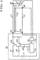
- FIG. 1 illustrates an embodiment of an electric discharge machine comprising a power supply 10 and a machine body, which includes a tool electrode 1 and a workpiece 2 being machined.
- the tool electrode 1 is positioned spaced from the workpiece 2 and defining therewith a machining gap G.
- the workpiece 2 is securely mounted on an appropriate work table (not illustrated) and submerged in a work tank (not illustrated) filled with a dielectric fluid.
- the machine body further includes a terminal 3A, which is connected to the tool electrode 1, and a terminal 3B which is connected to the workpiece 2. It is preferable that each of terminals 3A and 3B are positioned close to the gap G.
- the power supply 10 is provided for intermittently supplying a train of successive machining current pulses having a predetermined ON time to the gap G.
- the power supply 10 includes a d.c. power source 11, current limiting resistors R1 and R2 and switching transistors TR1 and TR2, all of which are connected in series with the gap G.
- Each one of the resistors R1 and R2 have different magnitudes of resistance, and each is connected in series with a respective one of the transistors TR1 and TR2.
- the series combinations of the resistors R1 and R2 and the transistors TR1 and TR2 are connected in parallel to each other between the power source 11 and the tool electrode 1. Though an additional combination of a current limiting resistor and a switching transistor may be provided, they have been omitted from FIG.
- the power supply 10 further includes a pulse generator 12 for generating a gating pulse signal GP1 having an ON time and an OFF time.
- the power supply 10 further includes a discharge detector 13 for monitoring a voltage VG at the gap G and supplying an output signal SP representative of an occurrence of electric discharges to the pulse generator 12.
- the pulse generator 12 supplies the gating pulse signal GP1 to the transistors TR1 and TR2 so that a voltage from the power source 11 is applied across the gap G to induce electric discharges and then a current flows through the gap G for a predetermined period of time.
- the power supply 10 includes a terminal 5A, which is connected to the positive terminal of the power source 11 through the transistors TR1 and TR2 and the resistors R1 and R2, and a terminal 5B which is connected to the negative terminal of the power source 11.
- Cables L1 and L2 are provided for carrying a current between the power supply 10 and the machine body.
- the cable L1 is connected to the terminal 5A of the power supply 10 at one end and connected to the terminal 3A of the machine body at the other end.
- the cable L2 is connected to the terminal 5B of the power supply 10 at one end and connected to the terminal 3B of the machine body at the other end.
- Each of the cables L1 and L2 are constituted as individual stranded conductors, which are composed of a group of copper wires of small diameters, to reduce the stray capacitance between the cables L1 and L2.
- a coaxial cable is provided for carrying a current between the power supply 10 and the machine body.
- the coaxial cable includes an inner-conductor L3 and a conductive shield L4 which is arranged coaxially with the inner-conductor L3 and insulated therefrom by an appropriate insulator.
- Each of the conductors L3 and L4 are smaller in cross-sectional area than the cables L1 and L2, for example, about half to reduce the stray inductance of the conductors L3 and L4. In other words, each of the conductors L3 and L4 are smaller in ampacity than the cables L1 and L2.
- the inner-conductor L3 is connected to the terminal 5A at one end and connected to the terminal 3A at the other end.
- the conductive shield L4 is connected to the terminal 5B at one end and connected to the terminal 3B at the other end. In other words, the conductors L3 and L4 are connected in parallel with the cables L1 and L2, respectively.
- the coaxial cable is used to reduce the inductance of the conductors L3 and L4.
- a twisted pair which is composed of two insulated conductors twisted together without a common covering, may be used.
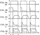
- FIGS. 3A, 3B, 3C, 3D and 3E are illustrative of waveforms of the gating pulse signal GP1, a voltage VG, a current i1 flowing through the cables L1 and L2, a current i2 flowing through the conductors L3 and L4, and a total current IG, i.e. , a combination of currents i1 and i2.
- the steady value of current i2 is inversely proportional to the total resistance of the conductors L3 and L4 and the gap G.
- the cables L1 and L2 are larger in cross-sectional area than the conductors L3 and L4 so that the steady value of current i1 is larger than that of current i2.
- the cables L1 and L2 and the conductors L3 and L4 are only sufficiently large to pass mean currents i1 and i2, respectively.
- the gating pulse signal GP1 is in an ON state a predetermined time after the generation of the signal SP. At the time t3, when the gating pulse signal GP1 is turned off, a current i2 suddenly drops. While, a current i1 gradually decreases. As shown in FIG. 3E, a total current IG flowing through the gap G has a steep slope on its leading edge.
- FIG. 2 illustrates another embodiment of an electric discharge machine, which is suitable, for example, for the machining of a cemented carbide workpiece by means of a copper tungsten electrode or the machining of a steel workpiece by means of a steel electrode. Similar elements are labelled with similar reference numerals as used in FIG. 1.
- a power supply 10A includes a first series combination consisting of the d.c. power source 11, a diode D1 for reverse-current protection, the current limiting resistor R1 and the switching transistor TR1, all of which are connected in series to the terminal 5A. Though an additional combination of a diode, a current limiting resistor and a switching transistor may be provided, they have been omitted from FIG. 2 in the interest of clarity and simplicity.
- the power supply 10A further includes a second series combination consisting of a variable voltage, d.c. power source 11B, adjustable between approximately 100 volts and 300 volts, and a switching transistor DTR.
- the power supply 10A includes a terminal 5C to which the inner-conductor L3 is connected at one end.
- the power source 11B is connected to the terminal 5C through the transistor DTR at its positive terminal and connected to the terminal 5B at its negative terminal.
- the first and second series combinations are connected in parallel to each other.
- the power supply 10A further includes a pulse generator 14, which is provided connected to the discharge detector 13 for generating a gating pulse signal GP2 having an ON time and an OFF time.
- each of the pulse generators 12 and 14 may include appropriate clock oscillator and counter.
- the pulse generator 14 turns on the transistor DTR so that a high peak current flows through the gap G a predetermined short time after an occurrence of electric discharges.
- a diode DR is provided between the cable L1 and the conductor L3 for preventing a voltage from the power source 11 from being applied across a spacing between the conductors L3 and L4.
- FIGS. 4A, 4B, 4C, 4D, 4E and 4F are illustrative of waveforms of the gating pulse signal GP1, a voltage VG, the signal SP, a current i1, a current i2, and a total current IG.
- the transistors TR1 and DTR are turned on.
- the power sources 11 and 11B apply a voltage across the gap G.
- electric discharges are caused to start in the gap G and a current i2 starts to flow through the gap G.
- a discharge detector detects drop of a voltage VG and supplies the signal SP to the pulse generators 12 and 14.
- the pulse generator 14 turns off the transistor DTR.
- the transistor DTR is closed at least about a half of the time during which a current i1 does not reach its steady value though a current flows through the gap G.
- a peak value of current i2 can be set to a desired value by adjusting a voltage of the power source 11B. Alternatively, it may be set by varying an ON time of the gating pulse signal GP2.
Landscapes
- Engineering & Computer Science (AREA)
- Mechanical Engineering (AREA)
- Electrical Discharge Machining, Electrochemical Machining, And Combined Machining (AREA)
Abstract
Description
- The present invention relates to an electroerosion machine. More specifically, the present invention relates to an electric discharge machine ("EDM") for performing electric discharge machining on a workpiece using a tool electrode in which a train of successive power pulses are supplied. from a power supply to a machine body including a machining gap formed between the tool electrode and the workpiece.
- In general, an electric discharge machine includes a machine body having a machining gap formed between a tool electrode and a workpiece being machined, a power supply for supplying electric energy to the machining gap and a dielectric supply device for supplying a dielectric fluid, such as kerosine or water, to the machining gap. The power supply is necessarily positioned with a physical spacing from the machine body and connected to the machine body by means of appropriate conductors.
- A train of successive voltage pulses from the power supply are applied across the machining gap to induce electric discharges across the machining gap so that a current starts to flow through the machining gap, thereby resulting in the machining of the workpiece.
- It is well known to use a coaxial cable, which has an inner-conductor and a conductive shield insulated from the inner-conductor, to reduce the undesirable self-inductance of the conductors connected between the power supply and the machine body. However, the stray capacitance between the inner-conductor and the shield adversely affects the quality of the machined surface of the workpiece particularly when a relatively long cable is used.
- An object of the present invention is to provide an electric discharge machine which can pass current pulses having a steep slope leading edge through a machining gap, thereby increasing machining speed even when a power supply is positioned at a long distance from a machine body.
- Another object of the present invention is to provide an electric discharge machine which prevents damages on the machined surface of a workpiece due to the stray capacitance between conductors connected between a power supply and a machine body.
- Additional objects, advantages and novel features of the invention will be set forth in part in the description which follows, and in part will become apparent to those skilled in the art upon examination of the following, or may be learned by practice of the invention. The objects and advantages of the invention may be realized and attained by means of the instrumentalities and combinations particularly pointed out in the appended claims.
- A general aspect of the present invention is the provision of an electric discharge machining apparatus for machining a workpiece by means of electric discharges having a tool electrode spaced from the workpiece and defining therewith a machining gap and a power supply for supplying a machining current to the machining gap and comprising: a first conductor having a first ampacity connected between the power supply and the tool electrode; a second conductor connected between the power supply and the workpiece; wherein the first and second conductors are so arranged to reduce the stray capacitance therebetween; a third conductor connected in parallel to the first conductor having a second ampacity smaller than the first ampacity; and a fourth conductor connected in parallel to the second conductor; wherein the third and fourth conductors are so arranged to reduce the inductance thereof.
- Another aspect of the present invention is the provision of a method of machining a workpiece using a tool electrode spaced from the workpiece and defining therewith a machining gap a power supply from which a machining current is intermittently supplied to the machining gap and comprising the steps of: connecting a first conductor between the power supply and the tool electrode; connecting a second conductor between the power supply and the workpiece in such a manner as to reduce the stray capacitance between the first and second conductors; connecting a third conductor in parallel to the first conductor: connecting a fourth conductor in parallel to the second conductor in such a manner as to reduce the inductance of the third and fourth conductors; passing a first current pulse from the power supply through the first conductor, the machining gap and the second conductor; and passing a second current pulse having a steep slope leading edge from the power supply through the third conductor, the machining gap and the fourth conductor during at least a portion of a leading edge of the first current pulse.
- The accompanying drawings, which are incorporated in and form a part of the specification, illustrate embodiments of the present invention and, together with the description, serve to explain the principles of the invention. In the drawings:
- FIG. 1 is a block diagram illustrating an embodiment of the invention as used in an electric discharge machine;
- FIG. 2 is a block diagram illustrating another embodiment of the invention as used in an electric discharge machine;
- FIGS. 3A to 3E are timing charts illustrating the. operation of the machine of FIG. 1; and
- FIGS. 4A to 4F are timing charts illustrating the operation of the machine of FIG. 2.
- An embodiment of the invention is described hereinafter in detail with reference to the drawings.
- FIG. 1 illustrates an embodiment of an electric discharge machine comprising a
power supply 10 and a machine body, which includes a tool electrode 1 and a workpiece 2 being machined. - The tool electrode 1 is positioned spaced from the workpiece 2 and defining therewith a machining gap G. The workpiece 2 is securely mounted on an appropriate work table (not illustrated) and submerged in a work tank (not illustrated) filled with a dielectric fluid. The machine body further includes a
terminal 3A, which is connected to the tool electrode 1, and aterminal 3B which is connected to the workpiece 2. It is preferable that each ofterminals - The
power supply 10 is provided for intermittently supplying a train of successive machining current pulses having a predetermined ON time to the gap G. Thepower supply 10 includes a d.c. power source 11, current limiting resistors R1 and R2 and switching transistors TR1 and TR2, all of which are connected in series with the gap G. Each one of the resistors R1 and R2 have different magnitudes of resistance, and each is connected in series with a respective one of the transistors TR1 and TR2. The series combinations of the resistors R1 and R2 and the transistors TR1 and TR2 are connected in parallel to each other between the power source 11 and the tool electrode 1. Though an additional combination of a current limiting resistor and a switching transistor may be provided, they have been omitted from FIG. 1 in the interest of clarity and simplicity. Thepower supply 10 further includes apulse generator 12 for generating a gating pulse signal GP1 having an ON time and an OFF time. Thepower supply 10 further includes adischarge detector 13 for monitoring a voltage VG at the gap G and supplying an output signal SP representative of an occurrence of electric discharges to thepulse generator 12. Thepulse generator 12 supplies the gating pulse signal GP1 to the transistors TR1 and TR2 so that a voltage from the power source 11 is applied across the gap G to induce electric discharges and then a current flows through the gap G for a predetermined period of time. Thepower supply 10 includes aterminal 5A, which is connected to the positive terminal of the power source 11 through the transistors TR1 and TR2 and the resistors R1 and R2, and aterminal 5B which is connected to the negative terminal of the power source 11. - Cables L1 and L2 are provided for carrying a current between the
power supply 10 and the machine body. In the illustrated embodiment, the cable L1 is connected to theterminal 5A of thepower supply 10 at one end and connected to theterminal 3A of the machine body at the other end. The cable L2 is connected to theterminal 5B of thepower supply 10 at one end and connected to theterminal 3B of the machine body at the other end. Each of the cables L1 and L2 are constituted as individual stranded conductors, which are composed of a group of copper wires of small diameters, to reduce the stray capacitance between the cables L1 and L2. - Additionally, a coaxial cable is provided for carrying a current between the
power supply 10 and the machine body. The coaxial cable includes an inner-conductor L3 and a conductive shield L4 which is arranged coaxially with the inner-conductor L3 and insulated therefrom by an appropriate insulator. Each of the conductors L3 and L4 are smaller in cross-sectional area than the cables L1 and L2, for example, about half to reduce the stray inductance of the conductors L3 and L4. In other words, each of the conductors L3 and L4 are smaller in ampacity than the cables L1 and L2. In the illustrated embodiment, the inner-conductor L3 is connected to theterminal 5A at one end and connected to theterminal 3A at the other end. The conductive shield L4 is connected to theterminal 5B at one end and connected to theterminal 3B at the other end. In other words, the conductors L3 and L4 are connected in parallel with the cables L1 and L2, respectively. - As will now be appreciated by the artisan, the coaxial cable is used to reduce the inductance of the conductors L3 and L4. Alternatively, a twisted pair, which is composed of two insulated conductors twisted together without a common covering, may be used.
- Operation of the machine shown in FIG. 1 will now be described with reference to FIGS. 3A, 3B, 3C, 3D and 3E. FIGS. 3A, 3B, 3C, 3D and 3E are illustrative of waveforms of the gating pulse signal GP1, a voltage VG, a current i1 flowing through the cables L1 and L2, a current i2 flowing through the conductors L3 and L4, and a total current IG, i.e., a combination of currents i1 and i2.
- At the time t1, when the gating pulse signal GP1 goes high, the transistors TR1 and TR2 are turned on. A voltage from the power source 11 is applied across the gap G. Thereby, at the time t2, electric discharges are caused to start in the gap G and a current i2 starts to flow through the gap G. As shown in FIG. 3D, a current i2 suddenly increases due to low inductance of the conductors L3 and L4. As shown in FIG. 3C, a current i1 gradually increases to its steady value while a current i2 decreases to its steady value, as shown in FIG. 3C. The steady value of current i1 is inversely proportional to the total resistance of the cables L1 and L2 and the gap G. The steady value of current i2 is inversely proportional to the total resistance of the conductors L3 and L4 and the gap G. In the illustrated embodiment, the cables L1 and L2 are larger in cross-sectional area than the conductors L3 and L4 so that the steady value of current i1 is larger than that of current i2. The cables L1 and L2 and the conductors L3 and L4 are only sufficiently large to pass mean currents i1 and i2, respectively. The gating pulse signal GP1 is in an ON state a predetermined time after the generation of the signal SP. At the time t3, when the gating pulse signal GP1 is turned off, a current i2 suddenly drops. While, a current i1 gradually decreases. As shown in FIG. 3E, a total current IG flowing through the gap G has a steep slope on its leading edge.
- FIG. 2 illustrates another embodiment of an electric discharge machine, which is suitable, for example, for the machining of a cemented carbide workpiece by means of a copper tungsten electrode or the machining of a steel workpiece by means of a steel electrode. Similar elements are labelled with similar reference numerals as used in FIG. 1.
- In FIG. 2, a
power supply 10A includes a first series combination consisting of the d.c. power source 11, a diode D1 for reverse-current protection, the current limiting resistor R1 and the switching transistor TR1, all of which are connected in series to theterminal 5A. Though an additional combination of a diode, a current limiting resistor and a switching transistor may be provided, they have been omitted from FIG. 2 in the interest of clarity and simplicity. - The
power supply 10A further includes a second series combination consisting of a variable voltage, d.c.power source 11B, adjustable between approximately 100 volts and 300 volts, and a switching transistor DTR. In addition, thepower supply 10A includes a terminal 5C to which the inner-conductor L3 is connected at one end. Thepower source 11B is connected to the terminal 5C through the transistor DTR at its positive terminal and connected to the terminal 5B at its negative terminal. The first and second series combinations are connected in parallel to each other. Thepower supply 10A further includes a pulse generator 14, which is provided connected to thedischarge detector 13 for generating a gating pulse signal GP2 having an ON time and an OFF time. For example, each of thepulse generators 12 and 14 may include appropriate clock oscillator and counter. The pulse generator 14 turns on the transistor DTR so that a high peak current flows through the gap G a predetermined short time after an occurrence of electric discharges. A diode DR is provided between the cable L1 and the conductor L3 for preventing a voltage from the power source 11 from being applied across a spacing between the conductors L3 and L4. - Operation of the machine shown in FIG. 2 will now be described with reference to FIGS. 4A, 4B, 4C, 4D 4E and 4F. FIGS. 4A, 4B, 4C, 4D, 4E and 4F are illustrative of waveforms of the gating pulse signal GP1, a voltage VG, the signal SP, a current i1, a current i2, and a total current IG.
- At the time t1, when the gating pulse signals GP1 and GP2 go high, the transistors TR1 and DTR are turned on. The
power sources 11 and 11B apply a voltage across the gap G. Thereby, at the time t2, electric discharges are caused to start in the gap G and a current i2 starts to flow through the gap G. At the time t2, a discharge detector detects drop of a voltage VG and supplies the signal SP to thepulse generators 12 and 14. After a predetermined short time upon receipt of the signal SP the pulse generator 14 turns off the transistor DTR. Preferably, the transistor DTR is closed at least about a half of the time during which a current i1 does not reach its steady value though a current flows through the gap G. A peak value of current i2 can be set to a desired value by adjusting a voltage of thepower source 11B. Alternatively, it may be set by varying an ON time of the gating pulse signal GP2. - The foregoing description of a preferred embodiment of the invention has been presented for purposes of illustration and description. It is not intended to be exhaustive or to limit the invention to the precise form disclosed, and obviously many modifications and variations are possible in the light of the above teaching. For example, a voltage may be applied across the gap G with the tool electrode 1 being negatively poled and the workpiece 2 being positively poled. It is intended that the scope of the invention be defined by the claims appended hereto.
Claims (6)
- An electric discharge machining apparatus for machining a workpiece by means of electric discharge having a tool electrode (1) spaced from said workpiece (2) and defining therewith a machining gap (G) and a power supply (10) for supplying a machining current to said machining gap, said apparatus comprising:
a first conductor (L1) having a first ampacity (current carrying capacity) connected between said power supply and said tool electrode;
a second conductor (L2) connected between said power supply and said workpiece;
wherein said first and second conductors are so arranged to reduce the stray capacitance therebetween;
a third conductor (L3) connected in parallel to said first conductor and having a second ampacity (current carrying capacity) smaller than said first ampacity (current carrying capacity); and
a fourth conductor (L4) connected in parallel to said second conductor;
wherein said third and fourth conductors are so arranged to reduce the inductance thereof. - An electric discharge machining apparatus according to Claim 1, wherein said third and fourth conductors form a coaxial cable having an inner-conductor and a shield insulated from said inner-conductor said inner-conductor being connected between said power supply and one of said tool electrode and said workpiece, said shield being connected between said power supply and the other of said tool electrode and said workpiece.
- An electric discharge machining apparatus according to Claim 1 or Claim 2, wherein said power supply includes a first power source (11), a first switching means (TR1,TR2) connected in series with said first power source and said machining gap for controlling the flow of current through said first and second conductors and said machining gap, a second power source (11b) and a second switching means (DTR) connected in series between said second power source and said machining gap for controlling the flow of current through said third and fourth conductors and said machining gap.
- An electric discharge machining apparatus according to Claim 3, wherein said power supply further includes a discharge detector (13) for detecting the occurrence of electric discharges, a first pulse generator (12) for supplying to said first switching means a first gating pulse signal having an ON time and an OFF time and a second pulse generator (14) responsive to said discharge detector for supplying a second gating pulse signal to said second switching means, said second pulse signal having an ON time a predetermined time after an occurrence of electric discharges.
- A method of machining a workpiece using a tool electrode (1) spaced from said workpiece (2) and defining therewith a machining gap (G) and a power supply (10) from which a machining current is intermittently supplied to said machining gap, comprising the steps of:
connecting a first conductor (L1) between said power supply and said tool electrode;
connecting a second conductor (L2) between said power supply and said workpiece in such a manner as to reduce the stray capacitance between said first and second conductors;
connecting a third conductor (L3) in parallel to said first conductor;
connecting a fourth conductor (L4) in parallel to said second conductor in such a manner as to reduce the inductance of said third and fourth conductors;
passing a first current pulse from said power supply through said first conductor, said machining gap and said second conductor; and
passing a second current pulse having a steep slope leading edge from said power supply through said third conductor, said machining gap and said fourth conductor during at least a portion of a leading edge of said first current pulse. - The method of Claim 6, wherein the step of connecting further comprising arranging said third conductor coaxially with said fourth conductor.
Applications Claiming Priority (2)
| Application Number | Priority Date | Filing Date | Title |
|---|---|---|---|
| JP05354942A JP3078441B2 (en) | 1993-12-24 | 1993-12-24 | Electric discharge machine |
| JP354942/93 | 1993-12-24 |
Publications (2)
| Publication Number | Publication Date |
|---|---|
| EP0659514A1 true EP0659514A1 (en) | 1995-06-28 |
| EP0659514B1 EP0659514B1 (en) | 1997-07-09 |
Family
ID=18440939
Family Applications (1)
| Application Number | Title | Priority Date | Filing Date |
|---|---|---|---|
| EP94309818A Expired - Lifetime EP0659514B1 (en) | 1993-12-24 | 1994-12-23 | Electric discharge machining apparatus |
Country Status (6)
| Country | Link |
|---|---|
| US (1) | US5572003A (en) |
| EP (1) | EP0659514B1 (en) |
| JP (1) | JP3078441B2 (en) |
| CN (1) | CN1059372C (en) |
| DE (1) | DE69404117T2 (en) |
| SG (1) | SG43084A1 (en) |
Cited By (1)
| Publication number | Priority date | Publication date | Assignee | Title |
|---|---|---|---|---|
| EP1719570A1 (en) * | 2005-05-06 | 2006-11-08 | Agie Sa | Method and apparatus for generating machining pulses for electrical discharge machining |
Families Citing this family (7)
| Publication number | Priority date | Publication date | Assignee | Title |
|---|---|---|---|---|
| JP2983139B2 (en) * | 1994-04-26 | 1999-11-29 | 株式会社ソディック | Power supply circuit for electric discharge machining and electric discharge machine |
| DE10195975T5 (en) * | 2001-02-22 | 2004-04-15 | Mitsubishi Denki K.K. | Discharge pulse generator |
| DE10109548B4 (en) * | 2001-02-28 | 2005-08-04 | Siemens Ag | Circuit arrangement for switching currents |
| US20050218089A1 (en) * | 2004-03-30 | 2005-10-06 | General Electric Company | Flushing and filtering system for electroerosion machining |
| JP4921481B2 (en) * | 2006-10-24 | 2012-04-25 | 三菱電機株式会社 | Wire electrical discharge machine |
| CN101318241B (en) * | 2008-04-08 | 2010-04-07 | 哈尔滨工业大学 | EDM small hole machining pulse power supply |
| CN106466747B (en) * | 2016-12-12 | 2018-08-31 | 上海东熠数控科技有限公司 | Discharge processing power source |
Citations (3)
| Publication number | Priority date | Publication date | Assignee | Title |
|---|---|---|---|---|
| JPS5973226A (en) * | 1982-10-20 | 1984-04-25 | Mitsubishi Electric Corp | Machining power supply of electric discharge machining device |
| JPS6156828A (en) * | 1984-08-24 | 1986-03-22 | Inoue Japax Res Inc | Wire-cut electric discharge machine |
| JPS62152618A (en) * | 1985-12-26 | 1987-07-07 | Hitachi Seiko Ltd | Wire electric discharge machine |
Family Cites Families (10)
| Publication number | Priority date | Publication date | Assignee | Title |
|---|---|---|---|---|
| US3348015A (en) * | 1961-11-14 | 1967-10-17 | Atellers Des Charmilles S A | Apparatus for machining by electro erosion |
| JPS5219359A (en) * | 1975-08-05 | 1977-02-14 | Takagi Seisakusho:Kk | Cattle turd dryer |
| JPS57138530A (en) * | 1981-02-13 | 1982-08-26 | Mitsubishi Electric Corp | Electric power source apparatus for machining with electrical discharge |
| US4491713A (en) * | 1981-10-28 | 1985-01-01 | Colt Industries Operating Corp. | Power and sensing cable arrangement for electrical discharge machining assembly |
| US4661674A (en) * | 1983-09-14 | 1987-04-28 | Inoue-Japax Research Incorporated | Minimum-impedance conductor assembly for EDM |
| JPS61219518A (en) * | 1985-03-22 | 1986-09-29 | Amada Co Ltd | Machining energy feeding circuit for electric discharge machine |
| JPS63156618A (en) * | 1986-12-22 | 1988-06-29 | Hoden Seimitsu Kako Kenkyusho Ltd | Electric discharge machine |
| JPS6427818A (en) * | 1987-07-21 | 1989-01-30 | Hitachi Seiko Kk | Wire electric discharge machine |
| JPH01257514A (en) * | 1988-04-08 | 1989-10-13 | Hoden Seimitsu Kako Kenkyusho Ltd | Power source for electric discharge machining |
| US5019685A (en) * | 1989-04-13 | 1991-05-28 | Sodick Co., Ltd. | Discharge working machine |
-
1993
- 1993-12-24 JP JP05354942A patent/JP3078441B2/en not_active Expired - Fee Related
-
1994
- 1994-12-23 US US08/363,759 patent/US5572003A/en not_active Expired - Lifetime
- 1994-12-23 SG SG1996003409A patent/SG43084A1/en unknown
- 1994-12-23 EP EP94309818A patent/EP0659514B1/en not_active Expired - Lifetime
- 1994-12-23 DE DE69404117T patent/DE69404117T2/en not_active Expired - Fee Related
- 1994-12-23 CN CN94120435A patent/CN1059372C/en not_active Expired - Lifetime
Patent Citations (3)
| Publication number | Priority date | Publication date | Assignee | Title |
|---|---|---|---|---|
| JPS5973226A (en) * | 1982-10-20 | 1984-04-25 | Mitsubishi Electric Corp | Machining power supply of electric discharge machining device |
| JPS6156828A (en) * | 1984-08-24 | 1986-03-22 | Inoue Japax Res Inc | Wire-cut electric discharge machine |
| JPS62152618A (en) * | 1985-12-26 | 1987-07-07 | Hitachi Seiko Ltd | Wire electric discharge machine |
Non-Patent Citations (3)
| Title |
|---|
| PATENT ABSTRACTS OF JAPAN vol. 008, no. 180 (M - 318) 18 August 1984 (1984-08-18) * |
| PATENT ABSTRACTS OF JAPAN vol. 010, no. 218 (M - 503) 30 July 1986 (1986-07-30) * |
| PATENT ABSTRACTS OF JAPAN vol. 011, no. 380 (M - 650) 11 December 1987 (1987-12-11) * |
Cited By (3)
| Publication number | Priority date | Publication date | Assignee | Title |
|---|---|---|---|---|
| EP1719570A1 (en) * | 2005-05-06 | 2006-11-08 | Agie Sa | Method and apparatus for generating machining pulses for electrical discharge machining |
| EP1808254A3 (en) * | 2005-05-06 | 2007-08-01 | Agie Sa | Method and apparatus for generating machining pulses for electrical discharge machining |
| US7582842B2 (en) | 2005-05-06 | 2009-09-01 | Agie Sa | Method and apparatus for generating machining pulses for electrical discharge machining |
Also Published As
| Publication number | Publication date |
|---|---|
| HK1000487A1 (en) | 1998-03-27 |
| EP0659514B1 (en) | 1997-07-09 |
| JPH07185937A (en) | 1995-07-25 |
| DE69404117T2 (en) | 1997-12-11 |
| JP3078441B2 (en) | 2000-08-21 |
| US5572003A (en) | 1996-11-05 |
| CN1059372C (en) | 2000-12-13 |
| DE69404117D1 (en) | 1997-08-14 |
| CN1112470A (en) | 1995-11-29 |
| SG43084A1 (en) | 1997-10-17 |
Similar Documents
| Publication | Publication Date | Title |
|---|---|---|
| EP0027041B1 (en) | Wire-cut electric-discharge machine, a power source for such a machine, and a method of wire-cut electric-discharge machining | |
| Han et al. | Basic study on pulse generator for micro-EDM | |
| MY132965A (en) | Method of and arrangement for eletrochemical machining | |
| EP0659514B1 (en) | Electric discharge machining apparatus | |
| US5770831A (en) | Power supply system for an electric discharge machine | |
| US5750951A (en) | Power supply system for an electric discharge machine | |
| US5897792A (en) | Power supply system for electrical discharge machining unit, and method for electrical discharge machining | |
| US6566823B2 (en) | Discharge pulse generator | |
| Yan et al. | Design, analysis and experimental study of a high-frequency power supply for finish cut of wire-EDM | |
| KR950007696B1 (en) | Power supply for electronic discharge making system | |
| HK1000487B (en) | Electric discharge machining apparatus | |
| GB1571776A (en) | Electric spark erosion process and machine | |
| EP3674026B1 (en) | Control method of wire electrical discharge machine | |
| US3549851A (en) | Power supply circuitry for increasing capacitance-charging rate and discharge duration in electric discharge machining apparatus | |
| JP4250377B2 (en) | Power supply for EDM | |
| US4443682A (en) | Superimposed high striking voltage power supply circuit for electrical discharge machining | |
| JPH0564032B2 (en) | ||
| CN1113722C (en) | Discharge processing power source and discharge processing method | |
| EP0038662A2 (en) | A power source arrangement for an electric discharge machine | |
| JPH06246545A (en) | Wire cut electric discharge machine | |
| GB2081633A (en) | Electrical discharge machining method and apparatus | |
| JPH059209B2 (en) | ||
| JPS5973226A (en) | Machining power supply of electric discharge machining device | |
| EP0185101A1 (en) | Power source for discharge machining | |
| JP2869538B2 (en) | Discharge current supply device for electric discharge machine |
Legal Events
| Date | Code | Title | Description |
|---|---|---|---|
| PUAI | Public reference made under article 153(3) epc to a published international application that has entered the european phase |
Free format text: ORIGINAL CODE: 0009012 |
|
| AK | Designated contracting states |
Kind code of ref document: A1 Designated state(s): DE FR GB IT |
|
| 17P | Request for examination filed |
Effective date: 19950812 |
|
| GRAG | Despatch of communication of intention to grant |
Free format text: ORIGINAL CODE: EPIDOS AGRA |
|
| 17Q | First examination report despatched |
Effective date: 19961004 |
|
| GRAH | Despatch of communication of intention to grant a patent |
Free format text: ORIGINAL CODE: EPIDOS IGRA |
|
| GRAH | Despatch of communication of intention to grant a patent |
Free format text: ORIGINAL CODE: EPIDOS IGRA |
|
| ITF | It: translation for a ep patent filed | ||
| GRAA | (expected) grant |
Free format text: ORIGINAL CODE: 0009210 |
|
| AK | Designated contracting states |
Kind code of ref document: B1 Designated state(s): DE FR GB IT |
|
| ET | Fr: translation filed | ||
| REF | Corresponds to: |
Ref document number: 69404117 Country of ref document: DE Date of ref document: 19970814 |
|
| PLBE | No opposition filed within time limit |
Free format text: ORIGINAL CODE: 0009261 |
|
| STAA | Information on the status of an ep patent application or granted ep patent |
Free format text: STATUS: NO OPPOSITION FILED WITHIN TIME LIMIT |
|
| 26N | No opposition filed | ||
| REG | Reference to a national code |
Ref country code: GB Ref legal event code: IF02 |
|
| PGFP | Annual fee paid to national office [announced via postgrant information from national office to epo] |
Ref country code: IT Payment date: 20071227 Year of fee payment: 14 |
|
| PGFP | Annual fee paid to national office [announced via postgrant information from national office to epo] |
Ref country code: GB Payment date: 20071219 Year of fee payment: 14 Ref country code: FR Payment date: 20071220 Year of fee payment: 14 |
|
| PGFP | Annual fee paid to national office [announced via postgrant information from national office to epo] |
Ref country code: DE Payment date: 20071220 Year of fee payment: 14 |
|
| GBPC | Gb: european patent ceased through non-payment of renewal fee |
Effective date: 20081223 |
|
| REG | Reference to a national code |
Ref country code: FR Ref legal event code: ST Effective date: 20090831 |
|
| PG25 | Lapsed in a contracting state [announced via postgrant information from national office to epo] |
Ref country code: DE Free format text: LAPSE BECAUSE OF NON-PAYMENT OF DUE FEES Effective date: 20090701 |
|
| PG25 | Lapsed in a contracting state [announced via postgrant information from national office to epo] |
Ref country code: GB Free format text: LAPSE BECAUSE OF NON-PAYMENT OF DUE FEES Effective date: 20081223 |
|
| PG25 | Lapsed in a contracting state [announced via postgrant information from national office to epo] |
Ref country code: FR Free format text: LAPSE BECAUSE OF NON-PAYMENT OF DUE FEES Effective date: 20081231 |
|
| PG25 | Lapsed in a contracting state [announced via postgrant information from national office to epo] |
Ref country code: IT Free format text: LAPSE BECAUSE OF NON-PAYMENT OF DUE FEES Effective date: 20081223 |