EP0659287B1 - Image-transfer process - Google Patents
Image-transfer process Download PDFInfo
- Publication number
- EP0659287B1 EP0659287B1 EP93919133A EP93919133A EP0659287B1 EP 0659287 B1 EP0659287 B1 EP 0659287B1 EP 93919133 A EP93919133 A EP 93919133A EP 93919133 A EP93919133 A EP 93919133A EP 0659287 B1 EP0659287 B1 EP 0659287B1
- Authority
- EP
- European Patent Office
- Prior art keywords
- layer
- transfer
- reaction layer
- image
- transfer film
- Prior art date
- Legal status (The legal status is an assumption and is not a legal conclusion. Google has not performed a legal analysis and makes no representation as to the accuracy of the status listed.)
- Expired - Lifetime
Links
Images
Classifications
-
- G—PHYSICS
- G03—PHOTOGRAPHY; CINEMATOGRAPHY; ANALOGOUS TECHNIQUES USING WAVES OTHER THAN OPTICAL WAVES; ELECTROGRAPHY; HOLOGRAPHY
- G03F—PHOTOMECHANICAL PRODUCTION OF TEXTURED OR PATTERNED SURFACES, e.g. FOR PRINTING, FOR PROCESSING OF SEMICONDUCTOR DEVICES; MATERIALS THEREFOR; ORIGINALS THEREFOR; APPARATUS SPECIALLY ADAPTED THEREFOR
- G03F1/00—Originals for photomechanical production of textured or patterned surfaces, e.g., masks, photo-masks, reticles; Mask blanks or pellicles therefor; Containers specially adapted therefor; Preparation thereof
- G03F1/68—Preparation processes not covered by groups G03F1/20 - G03F1/50
-
- G—PHYSICS
- G03—PHOTOGRAPHY; CINEMATOGRAPHY; ANALOGOUS TECHNIQUES USING WAVES OTHER THAN OPTICAL WAVES; ELECTROGRAPHY; HOLOGRAPHY
- G03F—PHOTOMECHANICAL PRODUCTION OF TEXTURED OR PATTERNED SURFACES, e.g. FOR PRINTING, FOR PROCESSING OF SEMICONDUCTOR DEVICES; MATERIALS THEREFOR; ORIGINALS THEREFOR; APPARATUS SPECIALLY ADAPTED THEREFOR
- G03F7/00—Photomechanical, e.g. photolithographic, production of textured or patterned surfaces, e.g. printing surfaces; Materials therefor, e.g. comprising photoresists; Apparatus specially adapted therefor
- G03F7/12—Production of screen printing forms or similar printing forms, e.g. stencils
-
- G—PHYSICS
- G03—PHOTOGRAPHY; CINEMATOGRAPHY; ANALOGOUS TECHNIQUES USING WAVES OTHER THAN OPTICAL WAVES; ELECTROGRAPHY; HOLOGRAPHY
- G03G—ELECTROGRAPHY; ELECTROPHOTOGRAPHY; MAGNETOGRAPHY
- G03G15/00—Apparatus for electrographic processes using a charge pattern
- G03G15/65—Apparatus which relate to the handling of copy material
- G03G15/6588—Apparatus which relate to the handling of copy material characterised by the copy material, e.g. postcards, large copies, multi-layered materials, coloured sheet material
- G03G15/6591—Apparatus which relate to the handling of copy material characterised by the copy material, e.g. postcards, large copies, multi-layered materials, coloured sheet material characterised by the recording material, e.g. plastic material, OHP, ceramics, tiles, textiles
-
- G—PHYSICS
- G03—PHOTOGRAPHY; CINEMATOGRAPHY; ANALOGOUS TECHNIQUES USING WAVES OTHER THAN OPTICAL WAVES; ELECTROGRAPHY; HOLOGRAPHY
- G03G—ELECTROGRAPHY; ELECTROPHOTOGRAPHY; MAGNETOGRAPHY
- G03G7/00—Selection of materials for use in image-receiving members, i.e. for reversal by physical contact; Manufacture thereof
- G03G7/0093—Image-receiving members, based on materials other than paper or plastic sheets, e.g. textiles, metals
-
- G—PHYSICS
- G03—PHOTOGRAPHY; CINEMATOGRAPHY; ANALOGOUS TECHNIQUES USING WAVES OTHER THAN OPTICAL WAVES; ELECTROGRAPHY; HOLOGRAPHY
- G03G—ELECTROGRAPHY; ELECTROPHOTOGRAPHY; MAGNETOGRAPHY
- G03G2215/00—Apparatus for electrophotographic processes
- G03G2215/00362—Apparatus for electrophotographic processes relating to the copy medium handling
- G03G2215/00443—Copy medium
- G03G2215/00523—Other special types, e.g. tabbed
- G03G2215/00527—Fabrics, e.g. textiles
-
- H—ELECTRICITY
- H05—ELECTRIC TECHNIQUES NOT OTHERWISE PROVIDED FOR
- H05K—PRINTED CIRCUITS; CASINGS OR CONSTRUCTIONAL DETAILS OF ELECTRIC APPARATUS; MANUFACTURE OF ASSEMBLAGES OF ELECTRICAL COMPONENTS
- H05K3/00—Apparatus or processes for manufacturing printed circuits
- H05K3/0002—Apparatus or processes for manufacturing printed circuits for manufacturing artworks for printed circuits
Definitions
- the invention relates to a method for transferring an image pattern contained on a template material onto a copy material.
- negative master copies are used, for example, for stamp production, for the production of printing plates or for screen printing processes.
- the production of the master copies by photographic means requires extensive equipment and a relatively high expenditure on equipment.
- the production of negative templates is generally not an option.
- a method for transferring an image pattern is known in which a toner image is first transferred to wax paper.
- the toner image is then completely detached from the wax paper and transferred to a transfer film, so that the toner overlaps and adheres to the transfer film.
- the toner image is then transferred together with parts of the transfer film onto an adhesive tape or a similar substrate. No negative transparency is created. It also does not take advantage of the property of the toner to adhere to the original material and, at the same time, to have the ability to bond to the transfer layer of a transfer film under pressure and heat and thus hold it to the original material.
- transfer materials which enable the colored coating of a photocopy in the contact process (EP 0 191 592, DE 4 110 801 C 1).
- Such a transfer or transfer film contains a transfer layer on a transparent carrier layer, which consists of a metal or pigment layer and a resin layer. If the resin layer is brought into contact with the toner material of a photocopy, it combines with the toner material under pressure and heat. When the carrier layer is peeled off, the transfer layer remains on the photocopy, the layers of the photocopy provided with toner then carrying the metal layer. In this way it is possible to optically change a photocopy in such a way that other colored areas can be seen instead of the blackened areas.
- a transfer film is not intended to make a copy of a template.
- the invention has for its object to provide a method for transferring an image pattern contained on a template material to a copy material, which can be carried out with little effort and can be carried out without the use of expensive equipment.
- the see-through image through which the reaction layer of the copying material is exposed is produced with a transfer film which has been provided with a negative pattern of the photocopy in the contact method with a photocopy.
- the part of the transfer film remaining after the transfer is used for photo technology in order to produce a relief image.
- the see-through image is not produced by photographic means, but rather by contact transfer with pressure and heat.
- the method according to the invention allows private individuals, school children, do-it-yourselfers or the like. enable them to produce stamps or other relief reproductions or surface patterns with a simple set of materials from a graphic positive.
- the process can also be used for the production of printed circuit boards in the photo-etching process. All that is required is the transfer film and the material containing the photosensitive reaction layer. Special equipment is not required. An iron with which pressure and heat can be exerted is sufficient to produce the see-through image with the transfer film.
- the reaction layer can be hardened with UV-containing daylight.
- the method according to the invention is also suitable for producing a copy material provided with an image pattern, the image of which on another Substrate is transferred, for example on a textile material.
- the process can also be used to make a cloth that can be used for the screen printing process translucent at selective points.
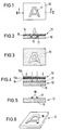
- Fig. 1 shows an original material 10 which consists of a sheet of paper on which an image pattern 11 of melted and hardened toner material has been produced by a photocopying process. From this image pattern 11, a positive relief image is to be generated on a copy material 12, which can be used as a stamp according to FIG. 6.
- the original material 10 is covered with a transfer film 13 which has a transparent carrier layer 14 and a transfer layer 15.
- the transfer layer 15 consists of a metal layer 15a and a resin layer 15b covering the metal layer 15a.
- the resin layer 15b melts with the melting one Toner layer that forms the image pattern 11.
- the transfer film 13 does not connect to the original material 10 at the other locations. If the transfer film 13 is subsequently removed from the original material 10, then the transfer layer 15 remains on the original material only at the locations of the image pattern 11 containing toner.
- This transfer film 13 is reversed according to Fig. 4, i.e. with the carrier layer down, placed on the copy material 12.
- the copying material 12 consists of a carrier material 16 which is coated with a photosensitive reaction layer 17 made of a photopolymer.
- the transfer film 13 is placed on this reaction layer 17 and exposed to actinic radiation.
- the reaction layer is exposed at those locations where the transfer film 13 is transparent, and the reaction layer 17 is not exposed at those locations where the metal layer 15a is obtained.
- the exposure takes place in the contact process, for example in daylight for a few minutes.
- the reaction layer 17 hardens at the exposed areas and remains soluble at the unexposed areas, so that they can be removed by rinsing with water.
- FIG. 5 shows the copying material 12 in which only the areas 18 of the reaction layer 17 which have been hardened by light are obtained and the remaining parts of the reaction layer are washed away.
- 6 represents a positive relief structure of the image pattern 11 contained on the original material 10 according to FIG. 1.
- the structure according to FIG. 6, ie the copying material 12 with the raised relief pattern, can be used as a stamp, for example as Name stamp, company stamp or motif stamp.
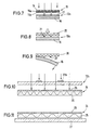
- FIGS. 7-9 a negative image is produced with the transfer film 13 in the same way as is shown in FIGS. 1-3 was explained.
- the embodiment of FIGS. 7-9 shows how the substrate 20, which is, for example, a textile material, can be printed using the transfer film carrying the negative image.
- the transfer sheet 13 is used to correct the page, i.e. with the carrier film 14 facing upwards, to selectively expose a copying material 12a.
- This copying material 12a consists of a carrier 16 made of paper or film, which is coated with a reaction layer 21.
- This reaction layer 21 contains on the one hand a photopolymer so that it hardens when exposed to light, and on the other hand a hot melt adhesive which can bond with other material under pressure and heat.
- the reaction layer 21 is selectively exposed through the transfer film 13 to harden at the exposed areas. The uncured areas are then washed out with a solvent.
- the copying material 12a is then covered with a substrate 20 which can be made of textile material, for example, and which is countered with an iron the copy material 12a is pressed.
- the hardened residues of the reaction layer 21 bond under pressure and heat to the substrate 20 to which they adhere when the carrier material 16 is removed.
- the image pattern 11 located on the original material 10 is transferred to the substrate 20 with the aid of the transfer film 13 and the copying material 12a.
- the method is suitable for transferring patterns that are contained on photocopies, for example on T-shirts. All you need is the transfer film, the copy material and an iron.
- Figures 10 and 11 show the production of a screen 24 made of textile material, which is suitable for the screen printing process.
- a positive pattern is produced on the copying material 12b from the hardened residues of the reaction layer 21.
- the carrier of the copying material 12b can be made of any rigid or flexible material.
- the screen 24 is exposed through the translucent copying material 12b, the light from the remainder of the reaction layer 21 not being transmitted.
- the screen 24 has a gauze layer 25 in the usual way. This gauze layer 25 is coated on one side with a light-sensitive reaction layer 26. When exposed through the copying material 12b, those areas of the reaction layer 26 which are below the hardened areas 21b of the copying material 12b are not exposed to light.
- the screen 24 is placed on a sheet of paper 27. Paint is then applied to the screen 24 and smoothed out with a squeegee. The ink then only reaches the paper 27 through the openings of the layer 26.
- textile material can also be printed, for example.
- the screen 24 can also be produced by creating a negative see-through image from a photocopy with the transfer film, which is then copied with a photocopier in order to obtain a negative paper copy. From this, a positive transfer image is generated with a transfer film, through which the light-sensitive layer of the screen is exposed.
Abstract
Description
Die Erfindung betrifft ein Verfahren zum Übertragen eines auf einem Vorlagenmaterial enthaltenen Bildmusters auf ein Kopiermaterial.The invention relates to a method for transferring an image pattern contained on a template material onto a copy material.
Es ist bekannt, negative Kopiervorlagen zum Belichten von lichtempfindlichen Materialien auf photographischem Wege zu erzeugen, indem ein Negativfilm hergestellt wird. Das auf dem Negativfilm enthaltene Negativ stellt das tonwertvertauschte Bild der Vorlage dar. Solche negativen Kopiervorlagen werden beispielsweise für die Stempelherstellung, für die Herstellung von Druckklischees oder für Siebdruckverfahren benutzt. Die Herstellung der Kopiervorlagen auf fotografischem Wege erfordert eine umfangreiche Ausrüstung und einen relativ hohen apparativen Aufwand. Für private Nutzer kommt somit die Herstellung negativer Kopiervorlagen in der Regel nicht in Betracht.It is known to make negative originals for exposing photosensitive materials photographically by making a negative film. The negative contained on the negative film represents the reversed image of the original. Such negative master copies are used, for example, for stamp production, for the production of printing plates or for screen printing processes. The production of the master copies by photographic means requires extensive equipment and a relatively high expenditure on equipment. For private users, the production of negative templates is generally not an option.
Aus DE-C-39 24 848 ist ein Verfahren zum Übertragen eines Bildmusters bekannt, bei dem ein Tonerbild zunächst auf Wachspapier übertragen wird. Von dem Wachspapier wird das Tonerbild anschließend komplett abgelöst und auf eine Übertragungsfolie übertragen, so daß der Toner die Übertragungsfolie überlagert und an dieser haftet. Anschließend wird das Tonerbild zusammen mit Teilen der Übertragungsfolie auf ein Klebeband oder ein ähnliches Substrat übertragen. Dabei wird kein negatives Durchsichtbild hergestellt. Es wird auch nicht die Eigenschaft des Toners ausgenutzt, an dem Vorlagenmaterial zu haften und gleichzeitig die Fähigkeit zu besitzen, sich unter Druck und Wärme mit der Übertragungsschicht einer Übertragungsfolie zu verbinden und diese somit am Vorlagenmaterial festzuhalten.From DE-C-39 24 848 a method for transferring an image pattern is known in which a toner image is first transferred to wax paper. The toner image is then completely detached from the wax paper and transferred to a transfer film, so that the toner overlaps and adheres to the transfer film. The toner image is then transferred together with parts of the transfer film onto an adhesive tape or a similar substrate. No negative transparency is created. It also does not take advantage of the property of the toner to adhere to the original material and, at the same time, to have the ability to bond to the transfer layer of a transfer film under pressure and heat and thus hold it to the original material.
Bekannt sind ferner Transfermaterialien, die im Kontaktverfahren die farbige Beschichtung einer Fotokopie ermöglichen (EP 0 191 592, DE 4 110 801 C 1).Also known are transfer materials which enable the colored coating of a photocopy in the contact process (EP 0 191 592, DE 4 110 801 C 1).
Eine solche Übertragungs- oder Transferfolie enthält auf einer transparenten Trägerschicht eine übertragungsschicht, die aus einer Metall- oder Pigmentschicht und einer Harzschicht besteht. Wird die Harzschicht mit dem Tonermaterial einer Fotokopie in Kontakt gebracht, so verbindet sie sich unter Druck und Wärme mit dem Tonermaterial. Beim Abziehen der Trägerschicht verbleibt die Übertragungsschicht an der Fotokopie, wobei die mit Toner versehenen Schichten der Fotokopie dann die Metallschicht tragen. Auf diese Weise ist es möglich, eine Fotokopie derart optisch zu verändern, daß anstelle der geschwärzten Stellen anders farbige Stellen zu sehen sind. Eine derartige Übertragungsfolie ist jedoch nicht dazu bestimmt, von einer Vorlage eine Kopie herzustellen.Such a transfer or transfer film contains a transfer layer on a transparent carrier layer, which consists of a metal or pigment layer and a resin layer. If the resin layer is brought into contact with the toner material of a photocopy, it combines with the toner material under pressure and heat. When the carrier layer is peeled off, the transfer layer remains on the photocopy, the layers of the photocopy provided with toner then carrying the metal layer. In this way it is possible to optically change a photocopy in such a way that other colored areas can be seen instead of the blackened areas. However, such a transfer film is not intended to make a copy of a template.
Der Erfindung liegt die Aufgabe zugrunde, ein Verfahren zum Übertragen eines auf einem Vorlagenmaterial enthaltenen Bildmusters auf ein Kopiermaterial anzugeben, das mit geringem Aufwand durchführbar ist und ohne Verwendung aufwendiger Apparaturen ausgeführt werden kann.The invention has for its object to provide a method for transferring an image pattern contained on a template material to a copy material, which can be carried out with little effort and can be carried out without the use of expensive equipment.
Die Lösung dieser Aufgabe erfolgt erfindungsgemäß mit den im Patentanspruch 1 angegebenen Merkmalen.This object is achieved according to the invention with the features specified in claim 1.
Bei dem erfindungsgemäßen Verfahren wird das Durchsichtbild, durch das hindurch die Reaktionsschicht des Kopiermaterials belichtet wird, mit einer Übertragungsfolie erzeugt, die im Kontaktverfahren mit einer Fotokopie mit einem Negativ-Muster der Fotokopie versehen worden ist. Dabei wird, wie bei Folien zum Einfärben von Fotokopien üblich, die Fotokopie an ihren geschwärzten Stellen mit der Übertragungsschicht der Übertragungsfolie beschichtet, jedoch wird der verbleibende Teil der Übertragungsfolie, nämlich die Trägerfolie mit dem in der Übertragungsschicht enthaltenen Negativbild, für die nachfolgende fotografische Herstellung des Bildmusters benutzt. Während bei einer Übertragungsfolie normalerweise nur die auf die Fotokopie übertragenen Bereiche der Übertragungsschicht ausgenutzt und der verbleibende Teil der Übertragungsfolie fortgeworfen wird, wird bei dem erfindungsgemäßen Verfahren der nach der Übertragung verbleibende Teil der Übertragungsfolie fototechnisch weiterbenutzt, um damit ein Reliefbild zu erzeugen. Die Herstellung des Durchsichtbildes erfolgt erfindungsgemäß nicht auf fotografischem Wege, sondern durch Kontaktübertragung mit Druck und Wärme.In the method according to the invention, the see-through image through which the reaction layer of the copying material is exposed is produced with a transfer film which has been provided with a negative pattern of the photocopy in the contact method with a photocopy. As with foils, it is used for coloring usual of photocopies, the photocopy coated at its blackened areas with the transfer layer of the transfer film, but the remaining part of the transfer film, namely the carrier film with the negative image contained in the transfer layer, is used for the subsequent photographic production of the image pattern. Whereas in a transfer film only the areas of the transfer layer transferred to the photocopy are normally used and the remaining part of the transfer film is thrown away, in the method according to the invention the part of the transfer film remaining after the transfer is used for photo technology in order to produce a relief image. According to the invention, the see-through image is not produced by photographic means, but rather by contact transfer with pressure and heat.
Das erfindungsgemäße Verfahren erlaubt es, auch Privatpersonen, Schulkinder, Heimwerker o.dgl. in die Lage zu versetzten, mit einem einfachen Materialsatz von einem grafischen Positiv Stempel oder andere Reliefreproduktionen oder Flächenmuster herzustellen. Das Verfahren kann auch für die Herstellung von Leiterplatten im Fotoätzverfahren eingesetzt werden. Benötigt werden lediglich die Übertragungsfolie und das die fotoempfindliche Reaktionsschicht enthaltende Material. Besondere Apparate sind nicht erforderlich. Für die Herstellung des Durchsichtbildes mit der übertragungsfolie genügt ein Bügeleisen, mit dem Druck und Wärme ausgeübt werden können. Das Härten der Reaktionsschicht kann mit UV-haltigem Tageslicht erfolgen.The method according to the invention allows private individuals, school children, do-it-yourselfers or the like. enable them to produce stamps or other relief reproductions or surface patterns with a simple set of materials from a graphic positive. The process can also be used for the production of printed circuit boards in the photo-etching process. All that is required is the transfer film and the material containing the photosensitive reaction layer. Special equipment is not required. An iron with which pressure and heat can be exerted is sufficient to produce the see-through image with the transfer film. The reaction layer can be hardened with UV-containing daylight.
Das erfindungsgemäße Verfahren eignet sich darüber hinaus auch zur Herstellung eines mit einem Bildmuster versehenen Kopiermaterials, dessen Bild auf ein anderes Substrat übertragen wird, z.B. auf ein Textilmaterial. Schließlich kann das Verfahren auch dazu benutzt werden, ein für das Siebdruckverfahren benutzbares Tuch an selektiven Stellen farbdurchlässig zu machen.The method according to the invention is also suitable for producing a copy material provided with an image pattern, the image of which on another Substrate is transferred, for example on a textile material. Finally, the process can also be used to make a cloth that can be used for the screen printing process translucent at selective points.
Im folgenden werden unter Bezugnahme auf die Zeichnungen Ausführungsbeispiele der Erfindung näher erläutert.Exemplary embodiments of the invention are explained in more detail below with reference to the drawings.
Es zeigen:
- Fig. 1
- eine Ansicht eines ein Bildmuster tragenden Vorlagenmaterials,
- Fig. 2
- in einem Schnitt entlang der Linie II-II von Fig. 1 die Übertragung des Bildmusters auf eine Übertragungsfolie,
- Fig. 3
- eine Ansicht der das Negativ des Bildmusters tragenden Übertragungsfolie,
- Fig. 4
- die Belichtung eines Kopiermaterials durch die Übertragungsfolie hindurch,
- Fig. 5
- ein Schnitt durch das Kopiermaterial mit den erhabenen Bildmusterstellen,
- Fig. 6
- eine perspektivische Darstellung des mit dem erhabenen Bildmuster versehenen Kopiermaterials das als Stempel benutzbar ist,
- Fig. 7
- bei einer anderen Form der Ausführungsform des Verfahrens das Belichten eines Kopiermaterials durch die das Negativ-Muster tragende Übertragungsfolie hindurch,
- Fig. 8
- die Übertragung des nach Fig. 7 auf dem kopiermaterialerzeugten Bildes auf ein Substrat,
- Fig. 9
- das Ablösen des Kopiermaterials von dem Substrat, so daß das Bild an dem Substrat haften bleibt,
- Fig. 10
- die Verwendung eines nach Fig. 7 hergestellten Kopiermaterials zum selektiven Belichten eines für ein nachfolgendes Siebdruckverfahren zu verwendenen Substrats und
- Fig. 11
- die Benutzung des nach Fig. 10 hergestellten Substrats für ein Siebdruckverfahren.
- Fig. 1
- 1 shows a view of a template material carrying an image pattern,
- Fig. 2
- in a section along the line II-II of Fig. 1, the transfer of the image pattern on a transfer film,
- Fig. 3
- a view of the transfer film carrying the negative of the image pattern,
- Fig. 4
- the exposure of a copy material through the transfer film,
- Fig. 5
- a section through the copy material with the raised image pattern locations,
- Fig. 6
- 1 shows a perspective illustration of the copying material provided with the raised image pattern, which can be used as a stamp,
- Fig. 7
- in another form of the embodiment of the method, the exposure of a copying material through the transfer film carrying the negative pattern,
- Fig. 8
- 7 the transfer of the image produced on the copying material according to FIG. 7 to a substrate,
- Fig. 9
- detaching the copying material from the substrate so that the image adheres to the substrate,
- Fig. 10
- the use of a copy material produced according to FIG. 7 for the selective exposure of a substrate to be used for a subsequent screen printing process and
- Fig. 11
- the use of the substrate produced according to FIG. 10 for a screen printing process.
Fig. 1 zeigt ein Vorlagenmaterial 10, das aus einem Blatt Papier besteht, auf dem durch ein Fotokopierverfahren ein Bildmuster 11 aus geschmolzenem und gehärteten Tonermaterial erzeugt worden ist. Von diesem Bildmuster 11 soll auf einem Kopiermaterial 12 ein positives Reliefbild erzeugt werden, das gemäß Fig. 6 als Stempel benutzt werden kann.Fig. 1 shows an
Das Vorlagenmaterial 10 wird entsprechend Fig. 2 mit einer Übertragungsfolie 13 bedeckt, die eine transparente Trägerschicht 14 und eine Übertragungsschicht 15 aufweist. Die Übertragungsschicht 15 besteht aus einer Metallschicht 15a und einer die Metallschicht 15a bedeckenden Harzschicht 15b. Wenn die Harzschicht 15b in fester Anlage an dem Vorlagenmaterial 10 liegt, verbindet sich bei Anwendung von Druck und Temperatur, indem, beispielsweise mit einem Bügeleisen, die Übertragungsfolie 13 gegen das Vorlagenmaterial 10 gedrückt wird, die Harzschicht 15b mit der aufschmelzenden Tonerschicht, die das Bildmuster 11 bildet. An den übrigen Stellen verbindet sich die Übertragungsfolie 13 nicht mit dem Vorlagenmaterial 10. Wird die übertragungsfolie 13 anschließend von dem Vorlagenmaterial 10 abgenommen, dann verbleibt die Übertragungsschicht 15 nur an den Toner aufweisenden Stellen des Bildmusters 11 am Vorlagenmaterial. An allen übrigen Stellen löst sich die an der Trägerfolie 14 haftende Übertragungsschicht 15 von dem Vorlagenmaterial. Dadurch entsteht das in Fig. 3 dargestellte negative Durchsichtbild der Übertragungsfolie 13, bei dem die Übertragungsschicht 15 im Bereich des Bildmusters fehlt. Die Übertragungsfolie 13 gemäß Fig. 3 bildet also ein Negativ des Vorlagenmaterials 10.2, the
Diese Übertragungsfolie 13 wird gemäß Fig. 4 seitenverkehrt, d.h. mit der Trägerschicht nach unten, auf das Kopiermaterial 12 aufgelegt. Das Kopiermaterial 12 besteht aus einem Trägermaterial 16, das mit einer fotoempfindlichen Reaktionsschicht 17 aus einem Fotopolymer beschichtet ist. Auf diese Reaktionsschicht 17 wird die Übertragungsfolie 13 gelegt und mit aktinischer Strahlung belichtet. An denjenigen Stellen, an denen die Übertragungsfolie 13 transparent ist, wird die Reaktionsschicht belichtet und an denjenigen Stellen, an denen die Metallschicht 15a erhalten ist, wird die Reaktionsschicht 17 nicht belichtet. Die Belichtung erfolgt im Kontaktverfahren beispielsweise bei Tageslicht über wenige Minuten. An den belichteten Stellen härtet die Reaktionsschicht 17 aus und an den unbelichteten Stellen bleibt sie löslich, so daß sie durch Spülen mit Wasser entfernt werden können.This
Fig. 5 zeigt das Kopiermaterial 12, bei dem nur die durch Licht gehärteten Stellen 18 der Reaktionsschicht 17 erhalten und die übrigen Teile der Reaktionsschicht fortgewaschen sind. Die gehärteten Stellen 18 stellen gemäß Fig. 6 eine positive Reliefstruktur des auf dem Vorlagenmaterial 10 gemäß Fig. 1 enthaltenen Bildmusters 11 dar. Die Struktur nach Fig. 6, d.h. das Kopiermaterial 12 mit dem erhabenen Reliefmuster, kann als Stempel benutzt werden, z.B. als Namenstempel, Firmenstempel oder Motivstempel.FIG. 5 shows the copying
Auch bei dem Ausführungsbeispiel der Fign. 7-9 wird mit der Übertragungsfolie 13 in gleicher Weise ein Negativbild hergestellt, wie dies an Hand der Fign. 1-3 erläutert wurde. Das Ausführungsbeispiel der Fign. 7-9 zeigt, wie mit Hilfe der das Negativbild tragenden Übertragungsfolie die Bedruckung eines Substrats 20 erfolgen kann, bei dem es sich beispielsweise um ein Textilmaterial handelt.Also in the embodiment of FIGS. 7-9, a negative image is produced with the
Zunächst wird gemäß Fig. 7 die Übertragungsfolie 13 dazu benutzt, seitenrichtig, d.h. mit nach oben gerichteter Trägerfolie 14, ein Kopiermaterial 12a selektiv zu belichten. Dieses Kopiermaterial 12a besteht aus einem Träger 16 aus Papier oder Folie, der mit einer Reaktionsschicht 21 beschichtet ist. Diese Reaktionsschicht 21 enthält einerseits einen Fotopolymer, so daß sie bei Lichteinfall härtet, und andererseits einen Schmelzklebstoff, der sich unter Druck und Wärme mit anderem Material verbinden kann. Die Reaktionsschicht 21 wird durch die Übertragungsfolie 13 hindurch selektiv belichtet, um an den belichteten Stellen zu härten. Die ungehärteten Bereiche werden anschließend mit einem Lösungsmittel ausgewaschen.First, according to Fig. 7, the
Dann wird gemäß Fig. 8 das Kopiermaterial 12a mit einem Substrat 20 bedeckt, das beispielsweise aus Textilmaterial betehen kann und das mit einem Bügeleisen gegen das Kopiermaterial 12a gedrückt wird. Dabei verbinden sich unter Druck und Wärme die gehärteten Reste der Reaktionsschicht 21 mit dem Substrat 20, an dem sie haften bleiben, wenn das Trägermaterial 16 abgezogen wird.8, the copying
Auf die beschriebene Weise wird das auf dem Vorlagenmaterial 10 befindliche Bildmuster 11 mit Hilfe der Übertragungsfolie 13 und des Kopiermaterials 12a auf das Substrat 20 übertragen. Das Verfahren eignet sich dazu, Muster, die auf Fotokopien enthalten sind, beispielsweise auf T-Shirts zu übertragen. Man benötigt hierzu lediglich die Übertragungsfolie, das Kopiermaterial sowie ein Bügeleisen.In the manner described, the
Die Figuren 10 und 11 zeigen die Herstellung eines aus Textilmaterial bestehenden Siebes 24, das für das Siebdruckverfahren geeignet ist. Zunächst wird, wie oben anhand der Fig. 7 erläutert wurde, auf einem Kopiermaterial 12b ein Positiv-Muster aus den gehärteten Resten der Reaktionsschicht 21 hergestellt. Der Träger des Kopiermaterials 12b kann aus einem beliebigen starren oder flexiblen Material bestehen. Durch das lichtdurchlässige Kopiermaterial 12b hindurch wird das Sieb 24 belichtet, wobei das Licht von den Resten der Reaktionsschicht 21 nicht durchgelassen wird. Das Sieb 24 weist in üblicher Weise eine Gazeschicht 25 auf. Diese Gazeschicht 25 ist an einer Seite mit einer lichtempfindlichen Reaktionsschicht 26 beschichtet. Bei Belichtung durch das Kopiermaterial 12b hindurch werden diejenigen Stellen der Reaktionsschicht 26, die unter den gehärteten Stellen 21b des Kopiermaterials 12b liegen, nicht mit Licht beaufschlagt. Diese Stellen werden somit nicht gehärtet und sie können anschließend mit Wasser oder mit einem anderen Lösungsmittel ausgewaschen werden. Es verbleiben dann nur die gehärteten Bereiche der Reaktionsschicht 26, die ein Negativ des Bildmusters 11 auf dem Vorlagenmaterial 10 darstellen. An den Stellen der gehärteten Reaktionsschicht 26 ist das Sieb 24 undurchlässig für Farbe.Figures 10 and 11 show the production of a
Gemäß Fig. 11 wird das Sieb 24 auf ein Blatt Papier 27 gelegt. Dann wird Farbe auf das Sieb 24 aufgetragen und mit einer Rakel glattgestrichen. Die Farbe gelangt dann nur durch die Öffnungen der Schicht 26 auf das Papier 27. Anstelle von Papier 27 kann auch beispielsweise Textilmaterial bedruckt werden.11, the
Die Herstellung des Siebes 24 kann auch in der Weise erfolgen, daß von einer Fotokopie mit der Übertragungsfolie ein negatives Durchsichtbild erstellt wird, welches anschließend mit einem Fotokopierer kopiert wird, um eine negative Papierkopie zu erhalten. Von dieser wird mit einer Übertragungsfolie ein positives Übertragungsbild erzeugt, durch das die lichtempfindliche Schicht des Siebes belichtet wird.The
Es ist auch möglich, von einer positiven Bildvorlage eine Kopie auf einer durchsichtigen Overheadfolie zu erzeugen. Diese wird mit der Übertragungsfolie beschichtet und dann für die Belichtung der lichtempfindlichen Schicht des Siebes benutzt. Durch die Beschichtung der Tonerschicht mit einer Übertragungsschicht wird das Lichtrückhaltevermögen verbessert, so daß eine exakte Belichtung möglich ist.It is also possible to make a copy of a positive image on a transparent overhead film. This is coated with the transfer film and then used to expose the photosensitive layer of the screen. By coating the toner layer with a transfer layer, the light retention capacity is improved, so that an exact exposure is possible.
Claims (5)
- A method for transfer of an image pattern formed on a master material (10) onto a copying material (12,12a,12b), wherein a negative transparent image corresponding to the image pattern of the master material (10) is produced and is used for exposing therethrough a photosensitive reaction layer (17,21) which then is further processed by removing material of the non-exposed regions of said layer,
characterized in
that the transparent image is generated by means of a transfer film (13) which is laid over the master material (10) provided as a photocopy, wherein those regions of the master material (10) which have toner arranged thereon become attached by pressure and heat to a light-retaining transfer layer (15a) of the transfer film (13) and remove the light-retaining transfer layer (15a) from a transparent carrier material (14) of the transfer film. - The method according to claim 1, characterized in that the copying material (12a,12b) comprises a carrier (16) coated with a reaction layer (21), that the reaction layer (21) includes a hot-melt adhesive or is coated therewith, and that those regions of the reaction layer which remain after exposure of the reaction layer (21) and removal of material from the non-exposed regions, are transferred by pressure and heat onto a substrate (20).
- The method according to claim 2, characterized in that the substrate (20) is a textile material.
- The method according to claim 1, characterized in that the copying material (12b) is used for exposure of a photosensitive reaction layer (26) of a screen (24) to render the screen (24) impermeable to colorants in selective regions, and that the screen (24) is used in a screen printing process.
- A method for transfer of an image pattern formed on a master material onto a copying material, comprising the following steps:a) by photocopying onto a transparent material, producing a transparent image corresponding to the image pattern of the master material,b) attaching the toner regions of the transparent material by pressure and heat to the transfer layer of a transfer film,c) exposing a photosensitive reaction layer through the transparent image,d) further processing the photosensitive reaction layer by removing material of the non-exposed regions of said layer.
Applications Claiming Priority (3)
| Application Number | Priority Date | Filing Date | Title |
|---|---|---|---|
| DE4230142A DE4230142C1 (en) | 1992-09-09 | 1992-09-09 | Use of a transfer film |
| DE4230142 | 1992-09-09 | ||
| PCT/EP1993/002249 WO1994006060A1 (en) | 1992-09-09 | 1993-08-21 | Image-transfer process |
Publications (2)
| Publication Number | Publication Date |
|---|---|
| EP0659287A1 EP0659287A1 (en) | 1995-06-28 |
| EP0659287B1 true EP0659287B1 (en) | 1996-10-30 |
Family
ID=6467595
Family Applications (1)
| Application Number | Title | Priority Date | Filing Date |
|---|---|---|---|
| EP93919133A Expired - Lifetime EP0659287B1 (en) | 1992-09-09 | 1993-08-21 | Image-transfer process |
Country Status (5)
| Country | Link |
|---|---|
| EP (1) | EP0659287B1 (en) |
| AT (1) | ATE144843T1 (en) |
| AU (1) | AU4951493A (en) |
| DE (2) | DE4230142C1 (en) |
| WO (1) | WO1994006060A1 (en) |
Families Citing this family (1)
| Publication number | Priority date | Publication date | Assignee | Title |
|---|---|---|---|---|
| DE19747877A1 (en) * | 1997-10-21 | 1999-04-29 | Rainer Eissing | Packaging to hold a stamp surface pre form for attachment to a printing stamp, pre form and stamp |
Family Cites Families (9)
| Publication number | Priority date | Publication date | Assignee | Title |
|---|---|---|---|---|
| GB356850A (en) * | 1930-06-28 | 1931-09-17 | George James Reynard Joyce | Methods and means for producing negatives by other means than photography |
| US2949848A (en) * | 1955-07-27 | 1960-08-23 | Haloid Xerox Inc | Stencil making |
| DE1025719B (en) * | 1955-09-17 | 1958-03-06 | Heinrich Heichlinger | Process for making negative transparencies |
| DE1920719A1 (en) * | 1968-04-25 | 1969-11-13 | Fuji Photo Film Co Ltd | Electrophotographic liquid developer |
| US3999481A (en) * | 1974-11-15 | 1976-12-28 | Xerox Corporation | Method for making a master |
| US4226930A (en) * | 1978-11-08 | 1980-10-07 | Nippon Paint Co., Ltd. | Electrophotographic method for producing photopolymer printing plate |
| JPS5746242A (en) * | 1980-09-03 | 1982-03-16 | Fuji Kagakushi Kogyo Co Ltd | Method for manufacturing negative for photoengraving |
| CA1243907A (en) * | 1985-02-05 | 1988-11-01 | Omnicrom Systems Corporation | Process for selective transfer of metallic foils to xerographic images |
| DE3924848C1 (en) * | 1989-07-27 | 1990-08-09 | Hans-Joachim 8903 Bobingen De Taschner |
-
1992
- 1992-09-09 DE DE4230142A patent/DE4230142C1/en not_active Expired - Fee Related
-
1993
- 1993-08-21 AU AU49514/93A patent/AU4951493A/en not_active Abandoned
- 1993-08-21 DE DE59304372T patent/DE59304372D1/en not_active Expired - Fee Related
- 1993-08-21 AT AT93919133T patent/ATE144843T1/en not_active IP Right Cessation
- 1993-08-21 EP EP93919133A patent/EP0659287B1/en not_active Expired - Lifetime
- 1993-08-21 WO PCT/EP1993/002249 patent/WO1994006060A1/en active IP Right Grant
Also Published As
| Publication number | Publication date |
|---|---|
| AU4951493A (en) | 1994-03-29 |
| DE59304372D1 (en) | 1996-12-05 |
| EP0659287A1 (en) | 1995-06-28 |
| ATE144843T1 (en) | 1996-11-15 |
| DE4230142C1 (en) | 1994-01-20 |
| WO1994006060A1 (en) | 1994-03-17 |
Similar Documents
| Publication | Publication Date | Title |
|---|---|---|
| DE2004214C3 (en) | Process for producing multicolored images | |
| DE2919137A1 (en) | ENERGY SENSITIVE MULTI-LAYER FILM FOR CREATING IMAGES | |
| DE3334993C2 (en) | ||
| DE3706528C2 (en) | ||
| DE2522656C2 (en) | Color proofing method by transferring partial color images | |
| DE2555855A1 (en) | ILLUSTRATION PROCEDURE | |
| DE1572058A1 (en) | Reprographic process | |
| US5972566A (en) | Releasable photopolymer printing plate and method of forming same | |
| EP0659287B1 (en) | Image-transfer process | |
| DE3322703A1 (en) | CHROMATIC PROOFREADING FILM | |
| DE2919055A1 (en) | PHOTOGRAPHIC SHEET MATERIAL SUITABLE FOR THE FORMATION OF A DRY PRINTING ELEMENT | |
| DE1696376A1 (en) | Method and apparatus for generating animated, polarized images | |
| DE2712864C2 (en) | ||
| DE4118922C2 (en) | ||
| DE2919138A1 (en) | ENERGY-SENSITIVE MULTI-LAYER FILM FOR GENERATING IMAGES AND METHOD FOR MANUFACTURING THIS FILM | |
| DE2623850A1 (en) | LIGHT-SENSITIVE MULTI-LAYER MATERIAL AND METHOD FOR IMAGE REPRODUCTION | |
| DE1946726C3 (en) | Laminated film for the production of a dry transfer material | |
| DE2809185C2 (en) | Process for the production of impressions using embossing foils | |
| EP0286919A3 (en) | Process for the production and transfer of a multicolour image | |
| CH651677A5 (en) | METHOD FOR THE PRODUCTION OF PRINT-LIKE PRODUCTS. | |
| DE3146753A1 (en) | METHOD FOR PRODUCING A PHOTOMECHANICAL COLOR IMAGE USING A REMOVABLE PHOTO TEMPLATE AND WATERPROOF, WATER-INSOLUBLE COLORANTS | |
| DE1597644C3 (en) | Process for the production of deer images | |
| DE1293587B (en) | Process for the production of transmission material | |
| AT146364B (en) | Process for producing the explanatory texts for the images on cinematographic films. | |
| DE360975C (en) | Method of making a stencil sheet for duplications |
Legal Events
| Date | Code | Title | Description |
|---|---|---|---|
| PUAI | Public reference made under article 153(3) epc to a published international application that has entered the european phase |
Free format text: ORIGINAL CODE: 0009012 |
|
| 17P | Request for examination filed |
Effective date: 19950208 |
|
| AK | Designated contracting states |
Kind code of ref document: A1 Designated state(s): AT DE ES FR GB IT SE |
|
| 17Q | First examination report despatched |
Effective date: 19951127 |
|
| GRAH | Despatch of communication of intention to grant a patent |
Free format text: ORIGINAL CODE: EPIDOS IGRA |
|
| GRAH | Despatch of communication of intention to grant a patent |
Free format text: ORIGINAL CODE: EPIDOS IGRA |
|
| GRAA | (expected) grant |
Free format text: ORIGINAL CODE: 0009210 |
|
| AK | Designated contracting states |
Kind code of ref document: B1 Designated state(s): AT DE ES FR GB IT SE |
|
| PG25 | Lapsed in a contracting state [announced via postgrant information from national office to epo] |
Ref country code: ES Free format text: THE PATENT HAS BEEN ANNULLED BY A DECISION OF A NATIONAL AUTHORITY Effective date: 19961030 |
|
| REF | Corresponds to: |
Ref document number: 144843 Country of ref document: AT Date of ref document: 19961115 Kind code of ref document: T |
|
| ITF | It: translation for a ep patent filed |
Owner name: ING. A. GIAMBROCONO & C. S.R.L. |
|
| GBT | Gb: translation of ep patent filed (gb section 77(6)(a)/1977) |
Effective date: 19961108 |
|
| REF | Corresponds to: |
Ref document number: 59304372 Country of ref document: DE Date of ref document: 19961205 |
|
| ET | Fr: translation filed | ||
| PG25 | Lapsed in a contracting state [announced via postgrant information from national office to epo] |
Ref country code: SE Effective date: 19970130 |
|
| PGFP | Annual fee paid to national office [announced via postgrant information from national office to epo] |
Ref country code: GB Payment date: 19970806 Year of fee payment: 5 |
|
| PGFP | Annual fee paid to national office [announced via postgrant information from national office to epo] |
Ref country code: FR Payment date: 19970818 Year of fee payment: 5 |
|
| PGFP | Annual fee paid to national office [announced via postgrant information from national office to epo] |
Ref country code: AT Payment date: 19970822 Year of fee payment: 5 |
|
| PLBE | No opposition filed within time limit |
Free format text: ORIGINAL CODE: 0009261 |
|
| STAA | Information on the status of an ep patent application or granted ep patent |
Free format text: STATUS: NO OPPOSITION FILED WITHIN TIME LIMIT |
|
| PGFP | Annual fee paid to national office [announced via postgrant information from national office to epo] |
Ref country code: DE Payment date: 19970917 Year of fee payment: 5 |
|
| RAP4 | Party data changed (patent owner data changed or rights of a patent transferred) |
Owner name: LIEBETRUTH, KAI |
|
| 26N | No opposition filed | ||
| PG25 | Lapsed in a contracting state [announced via postgrant information from national office to epo] |
Ref country code: GB Free format text: LAPSE BECAUSE OF NON-PAYMENT OF DUE FEES Effective date: 19980821 Ref country code: AT Free format text: LAPSE BECAUSE OF NON-PAYMENT OF DUE FEES Effective date: 19980821 |
|
| GBPC | Gb: european patent ceased through non-payment of renewal fee |
Effective date: 19980821 |
|
| PG25 | Lapsed in a contracting state [announced via postgrant information from national office to epo] |
Ref country code: FR Free format text: LAPSE BECAUSE OF NON-PAYMENT OF DUE FEES Effective date: 19990430 |
|
| PG25 | Lapsed in a contracting state [announced via postgrant information from national office to epo] |
Ref country code: DE Free format text: LAPSE BECAUSE OF NON-PAYMENT OF DUE FEES Effective date: 19990601 |
|
| REG | Reference to a national code |
Ref country code: FR Ref legal event code: ST |
|
| PG25 | Lapsed in a contracting state [announced via postgrant information from national office to epo] |
Ref country code: IT Free format text: LAPSE BECAUSE OF NON-PAYMENT OF DUE FEES;WARNING: LAPSES OF ITALIAN PATENTS WITH EFFECTIVE DATE BEFORE 2007 MAY HAVE OCCURRED AT ANY TIME BEFORE 2007. THE CORRECT EFFECTIVE DATE MAY BE DIFFERENT FROM THE ONE RECORDED. Effective date: 20050821 |